CN210323323U - Accurate anti-electric shock device in transformer platform district - Google Patents
Accurate anti-electric shock device in transformer platform district Download PDFInfo
- Publication number
- CN210323323U CN210323323U CN201921088766.4U CN201921088766U CN210323323U CN 210323323 U CN210323323 U CN 210323323U CN 201921088766 U CN201921088766 U CN 201921088766U CN 210323323 U CN210323323 U CN 210323323U
- Authority
- CN
- China
- Prior art keywords
- communication
- box body
- electric shock
- main control
- transformer
- Prior art date
- Legal status (The legal status is an assumption and is not a legal conclusion. Google has not performed a legal analysis and makes no representation as to the accuracy of the status listed.)
- Expired - Fee Related
Links
Images
Landscapes
- Remote Monitoring And Control Of Power-Distribution Networks (AREA)
Abstract
The utility model discloses an accurate protection against electric shock device in transformer platform district, including detector, communication equipment and the intelligent service portion of constituteing by box body, apron, main control panel, on the circuit was located to the detector, the main control panel was located in the box body, both all with communication equipment communication connection, communication equipment included the equipment cabinet body and communication assembly, the equipment cabinet body is equipped with solar cell panel. The utility model provides an accurate protection against electric shock device in transformer platform district uses the detector through the combination, communication equipment and intelligent service portion, whether there are trouble and trouble emergence point in can in time detecting line, and can in time remind the resident to avoid danger when breaking down, prevent to take place the casualties accident of electrocuteeing, can also in time take the initiative transmit management and control center and managers with trouble information, improve electric power maintainer's work efficiency and the service quality of power supply enterprise, communication equipment passes through the solar cell panel power supply, save the environmental protection pollution-free, for the reduce cost of enterprise.
Description
Technical Field
The utility model relates to an electric power maintenance technical field particularly, relates to accurate protection against electric shock device in transformer platform district.
Background
The power distribution network is an important component of the power system, bears the power supply service functions of most power users, is a key for guaranteeing power supply, and is the most important link influencing power supply reliability. At the present stage, the structure of a power distribution network in China is mainly a single-power radial distribution line, and the neutral point of a 10-35 kv power distribution system is mostly in a non-effective grounding mode, namely the neutral point is not grounded or is grounded through an arc suppression coil. When short-circuit fault occurs in such a system, the fault current is much smaller than the load current because a circuit can be formed only by the capacitance to ground, so the system is also called a low-current grounding system. According to incomplete statistics, more than 70% of short-circuit faults in a low-current grounding power distribution network are single-phase grounding faults.
The transformer platform district is the power supply scope or the region of a transformer, and when the transformer short circuit trouble took place, the tripping operation can appear in the transformer, and power supply company's relevant department is receiving the short circuit trouble and is informed after, and unable in time knows which circuit, and which transformer appears the tripping operation, and circuit maintainer need progressively investigate, just can find out the position point that the transformer tripped. Meanwhile, after the electricity utilization residents in the transformer area find power failure, the electricity utilization residents can go to the transformer trip point by themselves and push to reclose for power transmission, personal safety of the electricity utilization residents is threatened greatly, and service quality of power supply enterprises is influenced.
SUMMERY OF THE UTILITY MODEL
An object of the utility model is to provide an accurate protection against electric shock device in transformer platform district to can't in time fix a position trouble equipment point, cause the problem of potential safety hazard for the resident in the platform district when solving among the prior art transformer short-circuit fault.
In order to achieve the above object, the utility model provides an accurate protection against electric shock device in transformer platform district, including detector, communications facilities and intelligent service portion, wherein, the detector is used for setting up on the circuit that is detected, with communications facilities communication connection;
the intelligent service part comprises a box body and a cover plate, the box body is movably connected with the cover plate, a main control panel is arranged in the box body, and the main control panel is in communication connection with the communication equipment;
the communication equipment comprises an equipment cabinet body and a communication assembly, wherein the communication assembly is arranged in the equipment cabinet body, and a solar cell panel is arranged at the top of the equipment cabinet body and used for supplying power to the communication assembly.
Optionally, the number of the detectors is three, and the detectors are respectively hung on three lines.
Optionally, the communication assembly is provided with a first communication module, a controller and a battery, a communication antenna is arranged at the top of the equipment cabinet body, the first communication module and the communication antenna are electrically connected with the controller, and the battery is used for supplying power to all the parts and is connected with the solar cell panel.
Optionally, the solar cell panel is obliquely arranged at the top of the equipment cabinet body through a bracket.
Optionally, the detector is including detecting box body, joint ring and translucent cover, be equipped with on the detection box body and detect the master control board, the one end of detecting the box body be equipped with a pair of with detect the copper support that the master control board electricity is connected, the tip of joint ring pass through copper round pin axle with the connection can be dismantled to the copper support, the translucent cover install in the other end of detecting the box body.
Optionally, the other end of the detection box body is provided with an installation part, and the transparent cover is connected to the installation part in a clamping manner.
Optionally, be equipped with microcontroller, small-size battery and signal transceiver module on the installation department, microcontroller with signal transceiver module all with it connects to detect the master control board electricity, small-size battery provides the electric energy for each part.
Optionally, the box body is provided with a service antenna and a plug terminal which are electrically connected with the main control panel, and the cover plate is provided with a voice broadcast device and a control button which are connected with the main control panel.
Optionally, a second communication module, a main controller and an alarm module are arranged on the main control panel, the second communication module, the alarm module, the service antenna and the plug-in terminal are electrically connected with the main controller, the second communication module is in communication connection with the communication assembly, the alarm module is connected with the voice broadcast device, the control button is connected with the main controller, and the main controller is connected with an external leakage circuit breaker through a circuit.
Optionally, one side of the box body is hinged with one side of the cover plate, and the other opposite sides of the box body and the cover plate are connected through a lock catch, wherein,
the hasp includes the hasp piece, the one end of hasp piece is erect through articulated in the edge of apron, the lower extreme of hasp piece is equipped with the pothook, the middle part of hasp piece is equipped with the arch, the top edge of box body be equipped with hasp piece complex joint convex part, the lower limb of joint convex part with the pothook block, be equipped with the draw-in groove on the joint convex part, the hasp piece protruding card is gone into in the draw-in groove.
As above, the utility model provides an accurate protection against electric shock device in transformer platform district uses the detector through the combination, communication equipment and intelligent service portion, can in time detect whether have the emergence point of trouble and trouble in the circuit through the detector, can in time remind the resident to avoid danger through intelligent service portion when power equipment breaks down in the transformer platform district, prevent to take place the casualties accident of electrocution, and simultaneously, intelligent service portion can the real-time supervision electric leakage circuit breaker's state, and with communication equipment communication connection, can be timely initiative with fault information transmission to management and control center and managers, improve electric power maintainer's work efficiency and the quality of service of power supply enterprise. Moreover, the communication equipment is powered by the solar panel, an independent power supply circuit is not needed, electric energy can be saved, the environment is protected, no pollution is caused, cost is reduced for enterprises, and excessive maintenance is not needed.
In order to make the aforementioned and other objects of the present invention comprehensible, preferred embodiments accompanied with figures are described in detail below.
Drawings
The accompanying drawings, which form a part of the present application, are included to provide a further understanding of the invention, and are incorporated in and constitute a part of this specification, illustrate embodiments of the invention and together with the description serve to explain the invention and not to limit the invention. In the drawings:
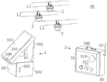
fig. 1 schematically shows an application layout of the accurate electric shock protection device for the transformer area of the present invention;
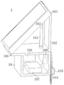
fig. 2 schematically shows an internal structure diagram of a communication device in the transformer area accurate electric shock prevention device of the present invention;
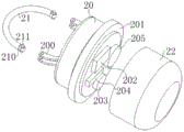
fig. 3 is a schematic diagram showing a structure of a detector in the transformer area accurate electric shock prevention device according to the present invention;
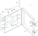
fig. 4 schematically shows the internal structure diagram of the intelligent service part in the transformer area accurate electric shock prevention device of the present invention.
Detailed Description
The following description is provided for illustrative embodiments of the present invention, and other advantages and effects of the present invention will be readily apparent to those skilled in the art from the disclosure herein. While the invention will be described in conjunction with the preferred embodiments, it is not intended that features of the invention be limited to only those embodiments. On the contrary, the intention of implementing the novel features described in connection with the embodiments is to cover other alternatives or modifications which may be extended based on the claims of the present invention. In the following description, numerous specific details are set forth in order to provide a thorough understanding of the present invention. The invention may be practiced without these particulars. Furthermore, some of the specific details are omitted from the description so as not to obscure or obscure the present invention.
It should be noted that the embodiments and features of the embodiments in the present application may be combined with each other without conflict. The present invention will be described in detail below with reference to the accompanying drawings in conjunction with embodiments.
Referring to fig. 1-4, an embodiment of the present invention provides an accurate electric shock protection apparatus 00 for transformer platform area, including a detector 2, a communication device 1 and an intelligent service unit 3, wherein the detector 2 is configured to be disposed on a detected line (as shown by lines L1, L2, and L3 in fig. 1), and is in communication connection with the communication device 1, the intelligent service unit 3 includes a box body 30 and a cover plate 31, the box body 30 is movably connected with the cover plate 31, a main control board 34 is disposed in the box body 31, the main control board 34 is in communication connection with the communication device 1, the communication device 1 includes a device cabinet 10 and a communication component (not shown in the figure), the communication component is disposed in the device cabinet 10, and a solar panel 103 is disposed at the top of the device cabinet 10 and is used for supplying power to the communication component.
That is to say, at accurate protection against electric shock device 00 in transformer platform district mainly by detector 2, communication equipment 1 and intelligent service portion 3 constitute, wherein, detector 2 hangs and establishes on the circuit, whether there is trouble and trouble emergence point in being used for detecting the circuit, communication equipment 1 and intelligent service portion 3 install at the transformer platform district, it avoids danger in time to remind the resident when electric power equipment breaks down in the transformer platform district, prevent to take place to electrocute casualties accident, and intelligent service portion can real-time supervision earth leakage circuit breaker's state, and can be through the timely initiative with trouble information transfer to staff and management and control center of communication equipment, electric power maintainer's work efficiency and power supply enterprise's quality of service have been improved greatly. A plurality of intelligent service units 3 and communication devices 1 may be provided according to the size of the transformer area.
Specifically, as shown in fig. 1 in combination with fig. 2, in this embodiment, the detector 2 is disposed on the line, and is in communication connection with the communication device 1, wherein the communication device 1 includes a device cabinet 10 and a communication component, the communication component is disposed in the device cabinet 10 and is in communication connection with the detector 2, the top of the device cabinet 10 is provided with the solar cell panel 103, the solar cell panel 103 can convert solar energy into electric energy, store the electric energy, supply power for the communication component, the communication component does not need an independent line for supplying power, the electric energy can be saved, energy conservation and environmental protection are achieved, pollution is avoided, cost can be reduced for an enterprise, and excessive maintenance is not needed.
In order to better receive sunlight, as shown in fig. 1-2, the solar panel 103 is disposed on the top 100 of the equipment cabinet 10 in an inclined manner by a bracket 102 in this embodiment.
It should be noted that the utility model discloses do not restrict the quantity of detector, can carry out reasonable setting according to the distance and the complexity of circuit. Referring to fig. 1, in the present embodiment, three detectors 2 are provided, which are respectively hung on three lines (as indicated by lines L1, L2, and L3 in fig. 1) and are communicatively connected to the communication module.
When breaking down, hang and establish detector 2 on the circuit and send out the police dispatch newspaper in time to give communication assembly with fault information transfer, in time transmit fault information to management and control center through communication assembly, the management and control center can in time know the serial number of fault location and trouble equipment according to the fault information of communication assembly transmission, the timely accurate understanding fault location and the trouble equipment of power supply company of being convenient for, maintenance work that can be timely. Simultaneously, through setting up a plurality of detectors 2, increase the check point for have multiple spot control, multiple spot alarm in whole transformer platform district, avoid the resident to get into the power failure region, ensure resident's personal safety, realize accurate anti-shock function.
It is further noted that the utility model discloses do not restrict the concrete structure of communication subassembly, can set up according to actual need, as long as can ensure that communication subassembly can be reliable and stable, accurate true and the detector between realize communication connection can. The utility model provides a communication connection means to connect through communication network between the equipment, can be wired connection, also can be wireless connection.
Specifically, referring to fig. 2, in this embodiment, the communication assembly is provided with a first communication module 108, a controller 106 and a battery 107, the top of the equipment cabinet 10 is provided with a communication antenna 101, the first communication module 108 and the communication antenna 101 are both electrically connected to the controller 106, and the battery 107 is used for supplying power to each component and is connected to the solar panel 103. The controller 106 receives the information of the detector 2 through the communication antenna 101, and transmits the information detected by the detector 2 to a remote device management and control center and a signal receiving device (such as a mobile phone) of a manager through the first communication module 108 after processing the information, so that the device management and control center and the manager can know the position of the short-circuit fault in time, maintain and eliminate the fault in time, and ensure stable and reliable work of a line.
Further, referring to fig. 3 and being shown in combination with fig. 1-2, in the utility model discloses in, detector 2 is including detecting box body 20, joint ring 21 and translucent cover 22, be equipped with on the detection box body 20 and detect the master control board 205, the one end of detecting box body 20 is equipped with a pair of copper support 200 with detecting the master control board 205 electricity and being connected, the tip 210 of joint ring 21 through copper round pin axle 211 with copper support 200 can dismantle the connection, translucent cover 22 install in the other end of detecting box body 20.
That is to say, the detector 2 mainly comprises a detection box body 20, a clamping ring 21 and a transparent cover 22, a detection main control board 205 is arranged in the detection box body 20, a pair of copper brackets 200 electrically connected with the detection main control board 205 is arranged at one end of the detection box body 20, and the end 210 of the clamping ring 21 is detachably connected with the copper brackets 200 through a copper pin shaft 211. When the device is installed, the copper pin shaft 211 at one end of the clamping ring 21 is detached, so that the clamping ring 21 is opened and hung on a line, the clamping ring 21 can be reliably contacted with the line, the current of the line is collected, the collected current is conveyed to the detection main control board 205, the collected current is processed by the detection main control board 205, and whether the line has a short-circuit fault or not is judged through a current signal. The detector 2 is convenient to arrange on the line through the clamping ring, is convenient to disassemble and assemble and use, and can stably and reliably acquire current information of the line.
Referring to fig. 1 to 3, in the present embodiment, a transparent cover 22 is installed at the other end of the detection box body 20, an installation portion 201 is arranged at the other end of the detection box body 20, and the transparent cover 22 is clamped on the installation portion 201.
Further, as shown in fig. 3, in the present invention, a microcontroller 204, a small battery 203 and a signal transceiver module 202 are disposed on the mounting portion 201, a main control board 205 is also disposed on the mounting portion 201, the microcontroller 204 and the signal transceiver module 202 are electrically connected to the main control board 205, and the small battery 203 provides electric energy for each component.
In this embodiment, the microcontroller 204 is electrically connected to the detection main control board 205, and is capable of receiving the current information of the line processed by the detection main control board 205, and transmitting the current information to the communication component in the communication device 1 through the signal transceiver module 202, and at the same time, is also capable of receiving the information transmitted by the communication component, and transmitting the received information to the detection main control board 205, thereby implementing modification of the parameters in the detection main control board 205.
Referring to fig. 4 in combination with fig. 1, in this embodiment, the intelligent service part 3 includes a box body 30 and a cover plate 31, the box body 30 is movably connected to the cover plate 31, a main control board 34 is disposed in the box body 30, the main control board 34 is in communication connection with the communication device 1, a service antenna 32 and a plug terminal 300 electrically connected to the main control board 34 are disposed on the box body 30, and a voice broadcast device 310 and a control button 311 connected to the main control board 34 are disposed on the cover plate 31.
Specifically, referring to fig. 4, in this embodiment, a second communication module 340, a main controller 341 and an alarm module 342 are disposed on the main control board 34, the second communication module 340, the alarm module 342, the service antenna 32 and the plug terminal 300 are all electrically connected to the main controller 341, the alarm module 342 is connected to the voice broadcaster 310, the control button 311 is connected to the main controller 341, and the main controller 341 is connected to an external electrical leakage breaker through a line.
When the ground fault happens to the circuit, when the earth leakage breaker trips, the earth leakage signal can be transmitted to the main controller 341, simultaneously, the main control panel 34 is still connected with the communication equipment 1 in a communication mode, the detector 2 can also transmit the fault information to the main controller 341 in the main control panel 34 through the communication equipment 1, the main controller 341 can issue the alarm information through the alarm module 342 and the voice broadcast device 310 electrically connected with the alarm module 342 after receiving the fault information, if broadcast "each resident who uses electricity please notice: because the power failure phenomenon of electric leakage occurs in the transformer area range, the transformer area is not privately close to push reclosure to touch power facilities, so that electric shock casualty accidents are avoided; the maintenance electrician receives the power failure information, is going to the local, asks for your patience to wait, expects that all users inform each other, and contacts the telephone: and voice contents such as the words of the words.
In addition, the main controller 341 sends the fault information to the communication device 1 in real time through the second communication module 340 on the main control board 34 and the service antenna 32 on the box body 30, and sends the fault information to the management and control center through the communication device 1. In addition, the main controller 341 may also directly transmit the failure information to the management and control center through the second communication module 340 and the service antenna 32. The management and control center can send the fault information to the manager in a short message mode after receiving the fault information, and simultaneously display the fault information on the display equipment of the management and control center, so that the manager can know and master the line fault information in the first time, and the fault can be maintained in time. Through being connected electric leakage circuit breaker and main control board 34 and communications link with communications facilities 1, can be timely initiative with fault information transmission to management and control center and managers, improved electric power maintainer's work efficiency and the quality of service of power supply enterprise greatly.
Referring to fig. 4, in the present embodiment, a battery 343 is further provided on the main control board 14, and the battery 343 is used for supplying power to the various components. In order to avoid the situation of insufficient battery power, in the present embodiment, a backup battery 344 is further provided on the main control board 34 side.
It should be noted that the utility model discloses do not restrict the concrete type of swing joint between box body and the apron, can be the joint, also can be the lock joint, can also be other types of swing joint, as long as can realize reliable connection between box body and the apron can.
Specifically, referring to fig. 4, in this embodiment, one side of the box body 30 is hinged to one side of the cover plate 31, and the opposite other side is connected through the latch 33, and the latch 33 has a simple connection structure, so that the cover plate 31 can be conveniently opened, and the components inside the box body 30 can be maintained and replaced. The utility model discloses do not limit to the concrete structure of hasp, can select according to actual need.
Specifically, as shown in fig. 4, in this embodiment, the lock catch 33 includes a lock catch block 331, one end of the lock catch block 331 is disposed on the edge of the cover plate 31 through the hinge frame 330, the lower end of the lock catch block 331 is provided with a hook 333, the middle of the lock catch block 331 is provided with a protrusion 332, the upper edge of the box body 30 is provided with a clamping protrusion 334 matched with the lock catch block 331, the lower edge of the clamping protrusion 334 is engaged with the hook 333, the clamping protrusion 334 is provided with a clamping groove 335, and the protrusion 332 of the lock catch block 331 is clamped into the clamping groove 335. Through the lower limb block of pothook 333 and joint convex part 334, through the protruding 332 block on the hasp piece 331 and the draw-in groove 335 block on the joint convex part 334, realize the dual block between box body 30 and the apron 31, not only make things convenient for the dismouting, do benefit to and maintain the box body 30 inner part, dual block moreover, safe and reliable can realize the reliable connection between box body 30 and the apron 31.
As for, be applied to the technical scheme the utility model discloses a transformer platform district accurate protection against electric shock device uses the detector through the combination, communication equipment and intelligent service portion, can in time detect whether there is the emergence point of trouble and trouble in the circuit through the detector, can in time remind the resident to avoid danger through intelligent service portion when power equipment breaks down in the transformer platform district, prevent to take place the casualties accident of electrocution, and simultaneously, intelligent service portion can the state of real-time supervision electric leakage circuit breaker, and with communication equipment communication connection, can be timely initiative with fault information transmission to management and control center and managers, improve electric power maintainer's work efficiency and the quality of service of power supply enterprise. Moreover, the communication equipment is powered by the solar panel, an independent power supply circuit is not needed, electric energy can be saved, the environment is protected, no pollution is caused, cost is reduced for enterprises, and excessive maintenance is not needed.
To sum up, the above embodiments provided by the present invention are merely illustrative of the principles and effects of the present invention, and are not intended to limit the present invention. Modifications and variations can be made to the above-described embodiments by those skilled in the art without departing from the spirit and scope of the present invention. Accordingly, it is intended that all equivalent modifications or changes which may be made by those skilled in the art without departing from the spirit and technical spirit of the present invention be covered by the claims of the present invention.
Claims (10)
1. The transformer platform area accurate electric shock prevention device is characterized by comprising a detector, communication equipment and an intelligent service part, wherein the detector is arranged on a detected line and is in communication connection with the communication equipment;
the intelligent service part comprises a box body and a cover plate, the box body is movably connected with the cover plate, a main control panel is arranged in the box body, and the main control panel is in communication connection with the communication equipment;
the communication equipment comprises an equipment cabinet body and a communication assembly, wherein the communication assembly is arranged in the equipment cabinet body, and a solar cell panel is arranged at the top of the equipment cabinet body and used for supplying power to the communication assembly.
2. The transformer platform area accurate electric shock prevention device according to claim 1, wherein three detectors are provided and hung on three lines respectively.
3. The transformer area accurate electric shock prevention device according to claim 1, wherein the communication assembly is provided with a first communication module, a controller and a battery, a communication antenna is arranged at the top of the equipment cabinet body, the first communication module and the communication antenna are both electrically connected with the controller, and the battery is used for supplying power to all parts and is connected with the solar panel.
4. The transformer platform area accurate electric shock prevention device according to claim 1, wherein the solar cell panel is obliquely arranged on the top of the equipment cabinet through a bracket.
5. The transformer area accurate electric shock prevention device according to any one of claims 1 to 3, wherein the detector comprises a detection box body, a clamping ring and a transparent cover, a detection main control board is arranged on the detection box body, a pair of copper brackets electrically connected with the detection main control board is arranged at one end of the detection box body, the end part of the clamping ring is detachably connected with the copper brackets through copper pin shafts, and the transparent cover is installed at the other end of the detection box body.
6. The transformer area accurate electric shock prevention device according to claim 5, wherein an installation part is arranged at the other end of the detection box body, and the transparent cover is clamped on the installation part.
7. The transformer platform area accurate electric shock prevention device according to claim 6, wherein a microcontroller, a small battery and a signal transceiver module are arranged on the mounting portion, the microcontroller and the signal transceiver module are electrically connected with the detection main control board, and the small battery provides electric energy for each component.
8. The transformer area precise electric shock prevention device as claimed in claim 1, wherein the box body is provided with a service antenna and a plug terminal electrically connected with the main control board, and the cover plate is provided with a voice broadcaster and a control button connected with the main control board.
9. The transformer platform area accurate electric shock prevention device according to claim 8, wherein a second communication module, a main controller and an alarm module are arranged on the main control board, the second communication module, the alarm module, the service antenna and the plug terminal are all electrically connected with the main controller, the second communication module is in communication connection with the communication assembly, the alarm module is connected with the voice broadcast device, the control button is connected with the main controller, and the main controller is connected with an external leakage circuit breaker through a circuit.
10. The transformer area precise electric shock prevention device according to claim 1, wherein one side of the box body is hinged with one side of the cover plate, and the other opposite sides are connected by a lock catch, wherein,
the hasp includes the hasp piece, the one end of hasp piece is erect through articulated in the edge of apron, the lower extreme of hasp piece is equipped with the pothook, the middle part of hasp piece is equipped with the arch, the top edge of box body be equipped with hasp piece complex joint convex part, the lower limb of joint convex part with the pothook block, be equipped with the draw-in groove on the joint convex part, the hasp piece protruding card is gone into in the draw-in groove.
Priority Applications (1)
| Application Number | Priority Date | Filing Date | Title |
|---|---|---|---|
| CN201921088766.4U CN210323323U (en) | 2019-07-12 | 2019-07-12 | Accurate anti-electric shock device in transformer platform district |
Applications Claiming Priority (1)
| Application Number | Priority Date | Filing Date | Title |
|---|---|---|---|
| CN201921088766.4U CN210323323U (en) | 2019-07-12 | 2019-07-12 | Accurate anti-electric shock device in transformer platform district |
Publications (1)
| Publication Number | Publication Date |
|---|---|
| CN210323323U true CN210323323U (en) | 2020-04-14 |
Family
ID=70150636
Family Applications (1)
| Application Number | Title | Priority Date | Filing Date |
|---|---|---|---|
| CN201921088766.4U Expired - Fee Related CN210323323U (en) | 2019-07-12 | 2019-07-12 | Accurate anti-electric shock device in transformer platform district |
Country Status (1)
| Country | Link |
|---|---|
| CN (1) | CN210323323U (en) |
Cited By (1)
| Publication number | Priority date | Publication date | Assignee | Title |
|---|---|---|---|---|
| CN112152100A (en) * | 2020-08-25 | 2020-12-29 | 华翔翔能科技股份有限公司 | Switch cabinet with monitoring and early warning functions |
-
2019
- 2019-07-12 CN CN201921088766.4U patent/CN210323323U/en not_active Expired - Fee Related
Cited By (1)
| Publication number | Priority date | Publication date | Assignee | Title |
|---|---|---|---|---|
| CN112152100A (en) * | 2020-08-25 | 2020-12-29 | 华翔翔能科技股份有限公司 | Switch cabinet with monitoring and early warning functions |
Similar Documents
| Publication | Publication Date | Title |
|---|---|---|
| CN211859281U (en) | Portable low pressure intelligence fast switch-on power supply box | |
| CN210323323U (en) | Accurate anti-electric shock device in transformer platform district | |
| CN106410622B (en) | A kind of mobile phone remote intelligent switchboard | |
| CN204203318U (en) | Terminal box of transformer substation and electric supply meter case alarm system for abnormal opening | |
| CN203242926U (en) | Low-voltage power distribution cabinet with residual current protection function | |
| CN107026424A (en) | A kind of distribution low-voltage master switch automatic time delay closing device | |
| CN208046018U (en) | A kind of distribution box with monitoring function | |
| CN203588057U (en) | Wind power monitoring device | |
| CN109802410A (en) | A kind of zero line break protection device and method | |
| CN210669637U (en) | Remote monitoring device based on wireless communication and cloud service | |
| CN210444625U (en) | End user intelligent service device | |
| CN212033834U (en) | Anti-islanding automatic alarm device | |
| CN102508101A (en) | Power cable operation fault monitoring terminal and system for detecting short circuit | |
| CN201450318U (en) | Automatic false ground preventive low-voltage power distribution device | |
| CN203025225U (en) | Combined type high-voltage prepayment metering device | |
| CN208385846U (en) | Integrated ring network cabinet with DTU | |
| CN210294445U (en) | 380V short-circuit fault positioning device | |
| CN111585341A (en) | Anti-islanding device of distributed power generation system | |
| CN106940390B (en) | Insulation detection switching device of direct current system | |
| CN216489719U (en) | User anti-reverse-electrification early warning monitoring device | |
| CN104901216A (en) | Handcart withdrawable capacitor compensation high-voltage power distribution cabinet and monitoring method thereof | |
| CN108128672A (en) | Elevator emergency communication system | |
| CN221633412U (en) | Intelligent alternating current leakage monitoring and protecting device | |
| CN114397835B (en) | Intelligent switch control system | |
| CN212588629U (en) | Intelligent guarding device for safety electricity utilization |
Legal Events
| Date | Code | Title | Description |
|---|---|---|---|
| GR01 | Patent grant | ||
| GR01 | Patent grant | ||
| CF01 | Termination of patent right due to non-payment of annual fee |
Granted publication date: 20200414 Termination date: 20210712 |
|
| CF01 | Termination of patent right due to non-payment of annual fee |