CN210321022U - Cloth drying device of weaving machine - Google Patents
Cloth drying device of weaving machine Download PDFInfo
- Publication number
- CN210321022U CN210321022U CN201920898953.2U CN201920898953U CN210321022U CN 210321022 U CN210321022 U CN 210321022U CN 201920898953 U CN201920898953 U CN 201920898953U CN 210321022 U CN210321022 U CN 210321022U
- Authority
- CN
- China
- Prior art keywords
- fixed
- supporting
- fixedly connected
- cloth
- drying device
- Prior art date
- Legal status (The legal status is an assumption and is not a legal conclusion. Google has not performed a legal analysis and makes no representation as to the accuracy of the status listed.)
- Expired - Fee Related
Links
Images


Landscapes
- Treatment Of Fiber Materials (AREA)
- Drying Of Solid Materials (AREA)
Abstract
The utility model discloses a cloth drying device of weaving machine, the on-line screen storage device comprises a base, the upper end of base is fixed with the backup pad, be equipped with the recess on the lateral wall of backup pad, the upper end of backup pad is equipped with servo motor, the fixed cover in servo motor's the outside is equipped with the mount, servo motor's one end and backup pad fixed connection are kept away from to the mount, servo motor's the terminal fixedly connected with dwang of output shaft, the lower extreme of dwang runs through the backup pad and rotates with terminal lateral wall in the recess to be connected, the cover is equipped with the movable block on the dwang, threaded connection between movable block and the dwang, be fixed with the mounting panel on the movable block, the lower extreme fixedly connected. This cloth drying device of weaving machine is to cloth stoving height and angle modulation convenience, makes the cloth stoving be heated evenly, has improved cloth drying efficiency.
Description
Technical Field
The utility model relates to a weaving relevant machine field specifically is a cloth drying device of weaving machine.
Background
The textile machines are also called textile machines, weaving machines, cotton spinning machines and the like, and the ancient textile machines are weaving machines driven by manpower. The textile machine is a general name of a tool for processing raw materials such as threads, silks, hemp and the like into silk threads and then weaving the silk threads into cloth. Such as spinning pendants, spinning wheels, spindles, pedal looms, modern mechanical looms, modern numerical control automatic looms and the like. The development of textile processes and equipment has been designed according to the textile raw materials, and therefore, the raw materials have an important position in the textile technology. The fibers used for spinning in all countries in the ancient world are all natural fibers, and are generally three types of short fibers (wool, hemp and cotton).
When the cloth of current weaving machine production is dried, the stoving height of drying apparatus is inconvenient with stoving angle modulation, and is inhomogeneous when leading to the stoving cloth, causes the cloth to dry production quality and reduces.
SUMMERY OF THE UTILITY MODEL
An object of the utility model is to provide a cloth drying device of weaving machine to the stoving height and the stoving angle modulation of drying apparatus are inconvenient when the cloth that proposes current weaving machine production in solving above-mentioned background art is dried, are inhomogeneous when leading to the stoving cloth, cause the problem that cloth stoving production quality reduces.
In order to achieve the above object, the utility model provides a following technical scheme: a cloth drying device of a textile machine comprises a base, wherein a supporting plate is fixed at the upper end of the base, a groove is formed in the outer side wall of the supporting plate, a servo motor is arranged at the upper end of the supporting plate, a fixing frame is fixedly sleeved on the outer side of the servo motor, one end, away from the servo motor, of the fixing frame is fixedly connected with the supporting plate, the tail end of an output shaft of the servo motor is fixedly connected with a rotating rod, the lower end of the rotating rod penetrates through the supporting plate and is rotatably connected with the side wall of the inner bottom of the groove, a moving block is sleeved on the rotating rod and is in threaded connection with the rotating rod, a mounting plate is fixed on the moving block, a connecting rod is fixedly connected with the lower end of the mounting plate, a rotating shaft is rotatably connected, the cloth conveying device is characterized in that a plurality of groups of symmetrical supporting mechanisms are fixed at the upper end of the base, each supporting mechanism comprises a supporting rod and a supporting sleeve, the supporting sleeves are fixed at the upper end of the corresponding supporting rod, a conveying roller is arranged between every two supporting sleeves, a plurality of cloth bodies are arranged at the upper end of the conveying roller, one end of the conveying roller penetrates through the supporting sleeves and is fixedly connected with a driven wheel, a driving motor is fixed at the upper end of the base, a driving wheel is fixedly connected to the tail end of an output shaft of the driving motor, and a driving belt is sleeved between.
Preferably, the upper end of base is equipped with the spout, be equipped with the slide bar in the spout, the both ends of slide bar respectively with spout in relative lateral wall fixed connection, the cover is equipped with the movable plate on the slide bar, be equipped with on the lateral wall of movable plate and fix its locking screw on the slide bar, be fixed with the fixed block on the upper end lateral wall of movable plate, the one end fixedly connected with fan of movable plate is kept away from to the fixed block, the air outlet of fan is in the face of the cloth body.
Preferably, adjusting device includes threaded rod and loop bar, the lower extreme at the mounting panel is fixed to the threaded rod, the loop bar cover is established in the outside of threaded rod, be equipped with the internal thread with the mutual interlock of threaded rod on the inside wall of loop bar, the lower extreme of loop bar offsets with the upper end lateral wall of drying apparatus.
Preferably, the lower pot head of base is equipped with the heelpiece, the heelpiece adopts the rubber material.
Preferably, the outer side wall of the moving block is provided with a storage groove, a ball is arranged in the storage groove, and the ball abuts against the inner side wall of the groove.
Preferably, the rotating rod is sleeved with a spring, and two ends of the spring are fixedly connected with the side wall of the lower end of the moving block and the side wall of the inner bottom end of the groove respectively.
Compared with the prior art, the beneficial effects of the utility model are that:
1. the cloth drying device is characterized in that a driving wheel is driven to rotate by a driving motor, a driven wheel is driven to rotate by a driving belt, a driving roller is driven to rotate by the driven wheel, the cloth body is conveyed, the cloth body is dried by a dryer, a rotating rod is driven to rotate by a servo motor, and the moving block moves on the rotating rod under the action of threads between the rotating rod and the moving block, so that the drying operation with different heights is realized;
2. the cloth drying machine has the advantages that the moving plate moves on the sliding rod and moves to the designated position, the locking screw rotates to the moving plate to be fixed on the sliding rod, blowing is completed through the fan fixed on the moving plate, and the drying speed of the cloth body is accelerated.
Drawings
Fig. 1 is a schematic structural view of a cloth drying device of a textile machine according to the present invention;
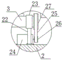
FIG. 2 is a schematic view of the structure at A in FIG. 1;
fig. 3 is a schematic structural view of a supporting mechanism of a cloth drying device of a textile machine of the present invention.
In the figure: the automatic cloth feeding device comprises a base pad 1, a base 2, a conveying roller 3, a cloth body 4, a spring 5, a ball 6, a servo motor 7, a fixing frame 8, a rotating rod 9, a moving block 10, a rotating shaft 11, a mounting plate 12, a connecting rod 13, a threaded rod 14, a loop bar 15, a dryer 16, a fan 17, a fixed block 18, a moving plate 19, a locking screw 20, a sliding rod 21, a supporting rod 22, a supporting rod 23, a supporting sleeve 24, a driving motor 25, a driving belt 26, a driving wheel 27 and a supporting plate 28.
Detailed Description
The technical solutions in the embodiments of the present invention will be described clearly and completely with reference to the accompanying drawings in the embodiments of the present invention, and it is obvious that the described embodiments are only some embodiments of the present invention, not all embodiments.
Referring to fig. 1-3, the present invention provides an embodiment: a cloth drying device of a textile machine comprises a base 2, a supporting plate 28 is fixed at the upper end of the base 2, a groove is arranged on the outer side wall of the supporting plate 28, a servo motor 7 is arranged at the upper end of the supporting plate 28, a fixing frame 8 is fixedly sleeved at the outer side of the servo motor 7, one end, far away from the servo motor 7, of the fixing frame 8 is fixedly connected with the supporting plate 28, a rotating rod 9 is fixedly connected with the tail end of an output shaft of the servo motor 7, the lower end of the rotating rod 9 penetrates through the supporting plate 28 and is rotatably connected with the side wall of the inner bottom end of the groove, a moving block 10 is sleeved on the rotating rod 9 and is in threaded connection with the rotating rod 9, the servo motor 7 drives the rotating rod 9 to rotate, the moving block 10 is driven by threads between the rotating rod 9 and the moving block 10 to, the lower end of the connecting rod 13 is rotatably connected with a rotating shaft 11, the lower end of the rotating shaft 11 is fixedly connected with a dryer 16, an adjusting device is arranged between the dryer 16 and the mounting plate 12, the upper end of the base 2 is fixed with a plurality of groups of symmetrically arranged supporting mechanisms, each supporting mechanism comprises a supporting rod 22 and a supporting sleeve 23, each supporting sleeve 23 is fixed at the upper end of each supporting rod 22, a conveying roller 3 is arranged between the two supporting sleeves 23, the upper ends of the plurality of conveying rollers 3 are provided with a cloth body 4, one end of each conveying roller 3 penetrates through each supporting sleeve 23 and is fixedly connected with a driven wheel 27, the upper end of the base 2 is fixed with a driving motor 24, the tail end of an output shaft of each driving motor 24 is fixedly connected with a driving wheel 26, a driving belt 25 is sleeved between each driving wheel 26 and each driven wheel 27, the driving wheel 26, the cloth body 4 is conveyed, and the cloth body 4 is dried through the dryer 16.
Further, the upper end of the base 2 is provided with a sliding groove, a sliding rod 21 is arranged in the sliding groove, two ends of the sliding rod 21 are respectively fixedly connected with opposite side walls in the sliding groove, a moving plate 19 is sleeved on the sliding rod 21, a locking screw 20 for fixing the moving plate 19 on the sliding rod 21 is arranged on the outer side wall of the moving plate 19, a fixed block 18 is fixed on the side wall of the upper end of the moving plate 19, one end, far away from the moving plate 19, of the fixed block 18 is fixedly connected with a fan 17, an air outlet of the fan 17 faces the cloth body 4, the moving plate 19 moves on the sliding rod 21 and moves to a designated position, the moving plate 19 is fixed on the sliding rod 21 through rotation of the locking screw 20, blowing is completed through the fan 17.
Further, adjusting device includes threaded rod 14 and loop bar 15, the lower extreme at mounting panel 12 is fixed to threaded rod 14, loop bar 15 cover is established in the outside of threaded rod 14, be equipped with the internal thread of 14 intermeshing with the threaded rod on the inside wall of loop bar 15, the lower extreme of loop bar 15 offsets with the upper end lateral wall of drying apparatus 16, rotate loop bar 15, the screw thread effect between loop bar 15 and the threaded rod 14, loop bar 15 moves down on threaded rod 14, pivot 11 on the promotion drying apparatus 16 rotates around connecting rod 13, realize the regulation of stoving angle, realized evenly drying to cloth body 4.
Further, the lower pot head of base 2 is equipped with heelpiece 1, and heelpiece 1 adopts the rubber material for increase the friction with ground, improve holistic stability.
Further, be equipped with on the lateral wall of movable block 10 and put the thing groove, put the thing inslot and be equipped with ball 6, ball 6 offsets with the recess inside wall for reduce the friction, improve movable block 10's removal efficiency.
Further, the cover is equipped with spring 5 on dwang 9, and spring 5's both ends respectively with movable block 10 lower extreme lateral wall, the terminal lateral wall fixed connection in the recess for realize the atress buffering that movable block 10 removed the in-process, improve stability.
The working principle is as follows: the driving wheel 26 is driven to rotate by the driving motor 24, the driving wheel 26 rotates to drive the driven wheel 27 to rotate by the driving belt 25, the driven wheel 27 rotates to drive the driving roller 3 to rotate, so that the cloth body 4 is conveyed, the cloth body 4 is dried by the dryer 16, the rotating rod 9 is driven to rotate by the servo motor 7, the thread action between the rotating rod 9 and the moving block 10 enables the moving block 10 to move on the rotating rod 9, so that the drying operation with different heights is realized, the sleeve rod 15 is driven to move downwards on the threaded rod 14 by rotating the sleeve rod 15, the rotating shaft 11 on the dryer 16 is pushed to rotate around the connecting rod 13, so that the drying angle is adjusted, the uniform drying of the cloth body 4 is realized, the drying efficiency is improved, the moving plate 19 moves on the sliding rod 21 to a designated position by moving the moving plate 19, and the moving plate 19 is fixed on the sliding rod 21 by the locking screw 20, the fan 17 fixed on the moving plate 19 completes the blowing, and the drying speed of the cloth body 4 is accelerated. This cloth drying device of weaving machine is to cloth stoving height and angle modulation convenience, makes the cloth stoving be heated evenly, has improved cloth drying efficiency.
It is obvious to a person skilled in the art that the invention is not restricted to details of the above-described exemplary embodiments, but that it can be implemented in other specific forms without departing from the spirit or essential characteristics of the invention. The present embodiments are therefore to be considered in all respects as illustrative and not restrictive, the scope of the invention being indicated by the appended claims rather than by the foregoing description, and all changes which come within the meaning and range of equivalency of the claims are therefore intended to be embraced therein. Any reference sign in a claim should not be construed as limiting the claim concerned.
Claims (6)
1. The utility model provides a cloth drying device of weaving machine, includes base (2), its characterized in that: the upper end of the base (2) is fixed with a supporting plate (28), the outer side wall of the supporting plate (28) is provided with a groove, the upper end of the supporting plate (28) is provided with a servo motor (7), the outer side of the servo motor (7) is fixedly provided with a fixing frame (8), one end, away from the servo motor (7), of the fixing frame (8) is fixedly connected with the supporting plate (28), the tail end of an output shaft of the servo motor (7) is fixedly connected with a rotating rod (9), the lower end of the rotating rod (9) penetrates through the supporting plate (28) and is rotatably connected with the side wall of the inner bottom of the groove, a moving block (10) is sleeved on the rotating rod (9), the moving block (10) is in threaded connection with the rotating rod (9), a mounting plate (12) is fixed on the moving block (10), and, the lower end of the connecting rod (13) is rotatably connected with a rotating shaft (11), the lower end of the rotating shaft (11) is fixedly connected with a dryer (16), an adjusting device is arranged between the dryer (16) and the mounting plate (12), a plurality of groups of symmetrically arranged supporting mechanisms are fixed at the upper end of the base (2), each supporting mechanism comprises a supporting rod (22) and a supporting sleeve (23), the supporting sleeves (23) are fixed at the upper ends of the supporting rods (22), a conveying roller (3) is arranged between every two supporting sleeves (23), a cloth body (4) is arranged at the upper ends of the conveying rollers (3), one end of each conveying roller (3) penetrates through the supporting sleeves (23) and is fixedly connected with a driven wheel (27), a driving motor (24) is fixed at the upper end of the base (2), and a driving wheel (26) is fixedly connected at the tail end of an output shaft of the, a transmission belt (25) is sleeved between the transmission wheel (26) and the driven wheel (27).
2. The cloth drying device of a textile machine according to claim 1, characterized in that: the upper end of base (2) is equipped with the spout, be equipped with slide bar (21) in the spout, the both ends of slide bar (21) respectively with spout in relative lateral wall fixed connection, the cover is equipped with movable plate (19) on slide bar (21), be equipped with on the lateral wall of movable plate (19) and fix its locking screw (20) on slide bar (21), be fixed with fixed block (18) on the upper end lateral wall of movable plate (19), the one end fixedly connected with fan (17) of movable plate (19) are kept away from in fixed block (18), the air outlet of fan (17) is in the face of cloth body (4).
3. The cloth drying device of a textile machine according to claim 1, characterized in that: adjusting device includes threaded rod (14) and loop bar (15), the lower extreme at mounting panel (12) is fixed in threaded rod (14), the outside at threaded rod (14) is established in loop bar (15) cover, be equipped with the internal thread with threaded rod (14) interlock each other on the inside wall of loop bar (15), the lower extreme of loop bar (15) offsets with the upper end lateral wall of drying-machine (16).
4. The cloth drying device of a textile machine according to claim 1, characterized in that: the lower pot head of base (2) is equipped with heelpiece (1), heelpiece (1) adopt the rubber material.
5. The cloth drying device of a textile machine according to claim 1, characterized in that: the outer side wall of the moving block (10) is provided with a storage groove, a ball (6) is arranged in the storage groove, and the ball (6) is abutted to the inner side wall of the groove.
6. The cloth drying device of a textile machine according to claim 1, characterized in that: the spring (5) is sleeved on the rotating rod (9), and two ends of the spring (5) are fixedly connected with the side wall of the lower end of the moving block (10) and the side wall of the bottom end in the groove respectively.
Priority Applications (1)
| Application Number | Priority Date | Filing Date | Title |
|---|---|---|---|
| CN201920898953.2U CN210321022U (en) | 2019-06-15 | 2019-06-15 | Cloth drying device of weaving machine |
Applications Claiming Priority (1)
| Application Number | Priority Date | Filing Date | Title |
|---|---|---|---|
| CN201920898953.2U CN210321022U (en) | 2019-06-15 | 2019-06-15 | Cloth drying device of weaving machine |
Publications (1)
| Publication Number | Publication Date |
|---|---|
| CN210321022U true CN210321022U (en) | 2020-04-14 |
Family
ID=70143931
Family Applications (1)
| Application Number | Title | Priority Date | Filing Date |
|---|---|---|---|
| CN201920898953.2U Expired - Fee Related CN210321022U (en) | 2019-06-15 | 2019-06-15 | Cloth drying device of weaving machine |
Country Status (1)
| Country | Link |
|---|---|
| CN (1) | CN210321022U (en) |
Cited By (2)
| Publication number | Priority date | Publication date | Assignee | Title |
|---|---|---|---|---|
| CN112683016A (en) * | 2020-12-23 | 2021-04-20 | 李逸 | Superfine fiber is drying device for non-woven fabrics based on new material |
| CN114908491A (en) * | 2022-06-27 | 2022-08-16 | 安徽优优时尚科技有限公司 | Uniform dyeing device for clothing production and processing method thereof |
-
2019
- 2019-06-15 CN CN201920898953.2U patent/CN210321022U/en not_active Expired - Fee Related
Cited By (2)
| Publication number | Priority date | Publication date | Assignee | Title |
|---|---|---|---|---|
| CN112683016A (en) * | 2020-12-23 | 2021-04-20 | 李逸 | Superfine fiber is drying device for non-woven fabrics based on new material |
| CN114908491A (en) * | 2022-06-27 | 2022-08-16 | 安徽优优时尚科技有限公司 | Uniform dyeing device for clothing production and processing method thereof |
Similar Documents
| Publication | Publication Date | Title |
|---|---|---|
| CN112249812A (en) | Yarn evenly winds package and puts with clearance function | |
| CN210321022U (en) | Cloth drying device of weaving machine | |
| CN106144757A (en) | A kind of textile machinery bobbin clamping device | |
| CN209295574U (en) | A kind of textile yarn drying unit | |
| CN208860068U (en) | A kind of fabric rotary drying device | |
| CN109282614B (en) | Cloth drying device is used in fabrics processing | |
| CN206396396U (en) | A kind of textile machines bracket | |
| CN105129484A (en) | Cloth guiding device | |
| CN111876954A (en) | Tensile wrinkle removal device of textile fabric | |
| CN215856540U (en) | Anti-static dust removing equipment for colored spun yarn production | |
| CN210418592U (en) | Textile fabric rolling and cutting device | |
| CN209113230U (en) | A kind of textile machines Thread-feeding device | |
| CN208562819U (en) | A kind of high efficiency yarn dyeing apparatus | |
| CN113321070B (en) | Automatic bobbin changing device for yarn storage bobbin | |
| CN209243383U (en) | A kind of garment production cloth arranging apparatus | |
| CN209097859U (en) | It is a kind of for improving the device of drying and setting machine delivery zone production stability | |
| CN207193481U (en) | A kind of colour-spun yarns ironing apparatus with dedusting function | |
| CN218345693U (en) | Automatic untwisting device for untwisting scutcher | |
| CN207376280U (en) | A kind of reciprocating rotation draw-off mechanism | |
| CN107447300B (en) | Carding machine is used in a kind of weaving of efficient adjustable | |
| CN207016925U (en) | A kind of drafting system for colour-spun yarns | |
| CN209456624U (en) | Simple and practical cotton carding device | |
| CN214655467U (en) | Spinning positioning device convenient to adjust | |
| CN219585467U (en) | Automatic centering winder in vulcanized paper production | |
| CN207243050U (en) | A kind of spinning roller device |
Legal Events
| Date | Code | Title | Description |
|---|---|---|---|
| GR01 | Patent grant | ||
| GR01 | Patent grant | ||
| CF01 | Termination of patent right due to non-payment of annual fee |
Granted publication date: 20200414 |
|
| CF01 | Termination of patent right due to non-payment of annual fee |