CN210308984U - Mold for quickly changing mold of bottle blowing machine - Google Patents
Mold for quickly changing mold of bottle blowing machine Download PDFInfo
- Publication number
- CN210308984U CN210308984U CN201921014886.XU CN201921014886U CN210308984U CN 210308984 U CN210308984 U CN 210308984U CN 201921014886 U CN201921014886 U CN 201921014886U CN 210308984 U CN210308984 U CN 210308984U
- Authority
- CN
- China
- Prior art keywords
- mold
- core
- bolt
- joint spare
- mould
- Prior art date
- Legal status (The legal status is an assumption and is not a legal conclusion. Google has not performed a legal analysis and makes no representation as to the accuracy of the status listed.)
- Active
Links
Images


Abstract
The utility model discloses a mould for quick retooling of bottle blowing machine, including preceding mould shell, preceding mould core, back mould shell, back mould core, die block support frame, preceding mould core includes preceding mould cavity, and back mould core includes the back mould cavity, and preceding mould shell is connected through first bolt and first joint spare with preceding mould core, and back mould shell passes through the second bolt with the back mould core and is connected with second joint spare, and the die block passes through the third bolt with the die block support frame and is connected with third joint spare, first joint spare, second joint spare, third joint spare, is the spout structure, preceding mould shell with back mould shell is symmetrical design, preceding mould core with back mould core is symmetrical design. Has the advantages that: the utility model discloses when changing the mould, only need take off first bolt, second bolt, third bolt, then the preceding mold core, back mold core to and the die block through first joint spare, second joint spare, third joint spare take out can, simple structure, convenient operation has practiced thrift operating time greatly, has promoted work efficiency.
Description
Technical Field
The utility model relates to a bottle blowing machine field, concretely relates to a mould that is used for quick retooling of bottle blowing machine.
Background
The bottle blowing machine is a device for manufacturing plastic particles into hollow containers through a blow molding process, and common machines include a hollow extrusion blow molding machine which uses PP and PE for one-step molding, an injection stretch blow molding machine which uses PET, PC or PP for two-step molding, and a newly developed multilayer hollow extrusion blow molding and stretch blow molding.
Most bottle blowing machines are two-step bottle blowing machines, i.e. plastic raw materials are made into bottle blanks firstly, and then blowing is carried out. Nowadays, environmental protection plastics made of PET are generally used. A blow molding machine: after the liquid plastic is sprayed, the plastic is blown to a mold cavity with a certain shape by the wind force blown out by a machine, so as to manufacture the product. Also relates to a bottle blowing machine, namely a hydraulic bottle blowing machine.
At present, the bottle blowing machine on the market needs to replace the mold after replacing the production product, but the replacement process is complicated, the operation is very inconvenient, and the work efficiency is delayed.
In order to improve the working efficiency and the defects, the die for quickly changing the die of the bottle blowing machine is provided.
SUMMERY OF THE UTILITY MODEL
The utility model aims to solve the problems and provide a mold for rapidly changing the mold of a bottle blowing machine.
The utility model discloses a following technical scheme realizes above-mentioned purpose.
The utility model provides a mould that is used for quick retooling of bottle blowing machine which characterized in that: including preceding mould shell, preceding mould core, back mould shell, back mould core, the die block support frame, preceding mould core includes preceding mould cavity, back mould core includes the back mould cavity, preceding mould shell is connected through first bolt and first joint spare with preceding mould core, first bolt setting is at preceding mould core top, back mould shell passes through the second bolt with the back mould core and is connected with second joint spare, the second bolt sets up at back mould core top, the die block passes through the third bolt with the die block support frame and is connected with third joint spare, the third bolt sets up in die block and die block support frame junction, die block support frame and bottle blowing machine fixed connection.
In order to further improve the use convenience of the mold for quickly changing the mold of the bottle blowing machine, the first clamping piece, the second clamping piece and the third clamping piece are of sliding groove structures, the first clamping piece comprises a first sliding groove seat and a first sliding groove rail, the second clamping piece comprises a second sliding groove seat and a second sliding groove rail, and the third clamping piece comprises a third sliding groove seat and a third sliding groove rail.
In order to further improve the use convenience of the mold for quickly changing the mold of the bottle blowing machine, the front mold core and the rear mold core are both wider than the front mold shell and the rear mold shell.
In order to further improve the use convenience of the mold for quickly changing the mold of the bottle blowing machine, the front mold shell and the rear mold shell are designed symmetrically.
In order to further improve the use convenience of the mold for quickly changing the mold of the bottle blowing machine, the front mold core and the rear mold core are symmetrically designed.
Has the advantages that: the utility model discloses when changing the mould, only need take off first bolt, second bolt, third bolt, then before mold core, back mold core and die block through first joint spare, second joint spare, third joint spare take out can, the design of preceding mold core and back mold core wide in preceding mould shell and back mold shell makes preceding mold core take out with the back mold core more easily, simple structure, and convenient operation has practiced thrift operating time greatly, has promoted work efficiency.
Drawings
Fig. 1 is a schematic view of the overall structure of the present invention.
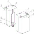
Fig. 2 is a schematic view of the overall structure split of the present invention.
Fig. 3 is a schematic view of the bottom mold of the present invention.
The reference numerals are explained below:
1. the mold comprises a front mold core, 2 parts of a rear mold core, 3 parts of a front mold shell, 4 parts of a rear mold shell, 5 parts of a first bolt, 6 parts of a bottom mold, 7 parts of a bottom mold support frame, 8 parts of a third bolt, 9 parts of a first sliding groove seat, 10 parts of a first sliding groove track, 11 parts of a third sliding groove seat, 12 parts of a third sliding groove track and 13 parts of a second bolt.
Detailed Description
The present invention will be further explained with reference to the accompanying drawings:
as shown in fig. 1-3, a mold for quickly changing molds of a bottle blowing machine comprises a front mold shell 3, a front mold core 1, a rear mold shell 4, a rear mold core 2, a bottom mold 6 and a bottom mold support frame 7; the front mold core 1 comprises a front mold cavity, the rear mold core 2 comprises a rear mold cavity, the front mold core 3 is connected with the front mold core 1 through a first bolt 5 and a first clamping piece, the rear mold shell 3 is connected with the rear mold core 1 through a second bolt 5 and a second clamping piece, the bottom mold 6 is connected with a bottom mold support frame 7 through a third bolt 8 and a third clamping piece, the bottom mold support frame 7 is fixedly connected with a bottle blowing machine, the first clamping piece, the second clamping piece and the third clamping piece are of a sliding groove structure, the first clamping piece comprises a first sliding groove seat 9 and a first sliding groove rail 10, the second clamping piece comprises a second sliding groove seat and a second sliding groove rail, the third clamping piece comprises a third sliding groove seat 11 and a third sliding groove rail 12, the front mold core 1 and the rear mold core 2 are both wider than the front mold shell 3 and the rear mold shell 4, and the front mold core 3, the front mold core 1 and the rear mold shell 4 and the rear mold core 2 are designed symmetrically.
The utility model discloses when changing the mould, only need to take off first bolt 5, second bolt 13, third bolt 8, later will preceding mold core 1, back mold core 2, die block 6 take out through first spout seat 11, first spout track 10, second spout seat, second spout track, third spout seat 11, third spout track 12, install required mold core, can accomplish the change to the mould.
The foregoing illustrates and describes the principles, general features, and advantages of the present invention. It will be understood by those skilled in the art that the present invention is not limited to the above embodiments, and that the foregoing embodiments and descriptions are provided only to illustrate the principles of the present invention without departing from the spirit and scope of the present invention.
Claims (5)
1. The utility model provides a mould that is used for quick retooling of bottle blowing machine which characterized in that: the mold comprises a front mold shell, a front mold core, a rear mold shell, a rear mold core, a bottom mold and a bottom mold support frame, wherein the front mold core comprises a front mold cavity, the rear mold core comprises a rear mold cavity, the front mold shell is connected with the front mold core through a first bolt and a first clamping piece, the first bolt is arranged at the top of the front mold core, the rear mold shell is connected with the rear mold core through a second bolt and a second clamping piece, the second bolt is arranged at the top of the rear mold core, the bottom mold is connected with the bottom mold support frame through a third bolt and a third clamping piece, the third bolt is arranged at the joint of the bottom mold and the bottom mold support frame, and the bottom mold support frame is fixedly connected with a bottle.
2. The mold for rapidly changing the mold of the bottle blowing machine according to claim 1, wherein: first joint spare, second joint spare, third joint spare are the spout structure, first joint spare includes first spout seat, first spout track, second joint spare includes second spout seat, second spout track, third joint spare includes third spout seat, third spout track.
3. The mold for rapidly changing the mold of the bottle blowing machine according to claim 1, wherein: the front mold core and the rear mold core are both wider than the front mold shell and the rear mold shell.
4. The mold for rapidly changing the mold of the bottle blowing machine according to claim 1, wherein: the front formwork and the rear formwork are designed symmetrically.
5. The mold for rapidly changing the mold of the bottle blowing machine according to claim 1, wherein: the front mold core and the rear mold core are designed symmetrically.
Priority Applications (1)
| Application Number | Priority Date | Filing Date | Title |
|---|---|---|---|
| CN201921014886.XU CN210308984U (en) | 2019-07-02 | 2019-07-02 | Mold for quickly changing mold of bottle blowing machine |
Applications Claiming Priority (1)
| Application Number | Priority Date | Filing Date | Title |
|---|---|---|---|
| CN201921014886.XU CN210308984U (en) | 2019-07-02 | 2019-07-02 | Mold for quickly changing mold of bottle blowing machine |
Publications (1)
| Publication Number | Publication Date |
|---|---|
| CN210308984U true CN210308984U (en) | 2020-04-14 |
Family
ID=70147883
Family Applications (1)
| Application Number | Title | Priority Date | Filing Date |
|---|---|---|---|
| CN201921014886.XU Active CN210308984U (en) | 2019-07-02 | 2019-07-02 | Mold for quickly changing mold of bottle blowing machine |
Country Status (1)
| Country | Link |
|---|---|
| CN (1) | CN210308984U (en) |
Cited By (1)
| Publication number | Priority date | Publication date | Assignee | Title |
|---|---|---|---|---|
| CN113681867A (en) * | 2021-10-27 | 2021-11-23 | 山东中茂散热器有限公司 | Blowing machine convenient to change mould |
-
2019
- 2019-07-02 CN CN201921014886.XU patent/CN210308984U/en active Active
Cited By (1)
| Publication number | Priority date | Publication date | Assignee | Title |
|---|---|---|---|---|
| CN113681867A (en) * | 2021-10-27 | 2021-11-23 | 山东中茂散热器有限公司 | Blowing machine convenient to change mould |
Similar Documents
| Publication | Publication Date | Title |
|---|---|---|
| CN210308984U (en) | Mold for quickly changing mold of bottle blowing machine | |
| CN206765247U (en) | The mould structure at the mouth of a river is automatically cut off in a kind of mould | |
| CN201559311U (en) | Full automatic mold closing locking mechanism for bottle blowing machine | |
| CN106426883A (en) | Plastic bottle blow molding mold node shear member | |
| CN108327194A (en) | A kind of plastic mould thimble pushing meanss | |
| CN206066927U (en) | A kind of node cutting member of plastic bottle blowing mould | |
| CN204278396U (en) | A kind of support injection mold | |
| CN201056050Y (en) | Vertically lifting type plastics extrusion blow machine | |
| CN203381153U (en) | Injection mould for wiring board | |
| CN206030504U (en) | Storage formula blowing machine | |
| CN206780930U (en) | A kind of bidirectional locking injection mold group | |
| CN203305248U (en) | Bottle mouth cutting machine | |
| CN204451075U (en) | A kind of injection mold for making clip | |
| CN202985961U (en) | Plastic mould for pergola central connector | |
| CN207696942U (en) | A kind of easily demoulding automobile lampshade mold | |
| CN206812418U (en) | A kind of blow mold mould undercut construction | |
| CN205033482U (en) | Electron connects injection mold | |
| CN205628952U (en) | Novel aluminum section -Bar extruding mould | |
| CN206030411U (en) | Quick -operation joint mould of auto -parts plastic housing production | |
| CN204725777U (en) | Eliminate the mould of injection mould weld mark | |
| CN219114765U (en) | Blow molding mold for automobile air duct | |
| CN204914419U (en) | Three high -efficient matrix moulds | |
| CN204955468U (en) | Crowded cold press molding mould of building ash bucket heat | |
| CN205058484U (en) | Injection mold that plastic flows in adjustable die cavity | |
| CN206416445U (en) | A kind of sealing ring flexible glue plastic mould |
Legal Events
| Date | Code | Title | Description |
|---|---|---|---|
| GR01 | Patent grant | ||
| GR01 | Patent grant |