CN210305965U - Pipeline cutting device for municipal works - Google Patents
Pipeline cutting device for municipal works Download PDFInfo
- Publication number
- CN210305965U CN210305965U CN201921307421.3U CN201921307421U CN210305965U CN 210305965 U CN210305965 U CN 210305965U CN 201921307421 U CN201921307421 U CN 201921307421U CN 210305965 U CN210305965 U CN 210305965U
- Authority
- CN
- China
- Prior art keywords
- fixedly connected
- frame
- motor
- base
- sliding
- Prior art date
- Legal status (The legal status is an assumption and is not a legal conclusion. Google has not performed a legal analysis and makes no representation as to the accuracy of the status listed.)
- Expired - Fee Related
Links
Images


Landscapes
- Sawing (AREA)
Abstract
The utility model relates to the technical field of pipeline cutting, in particular to a pipeline cutting device for municipal engineering, which comprises a base, a lifting rod and a pipe frame, wherein the top end of the base is fixedly connected with a fixed frame, the inner side of the base is fixedly connected with a first motor, the end of a main shaft of the first motor is fixedly connected with a first screw rod, the outer side of the first screw rod is in threaded connection with the lifting rod, the lifting rod is in sliding connection with the fixed frame, the inner side of the top end of the lifting rod is in sliding connection with a tooth groove frame, the bottom end of the tooth groove frame is fixedly connected with a sliding plate, the sliding plate is in sliding connection with the inner side of the lifting rod, the bottom end of the sliding plate is fixedly connected with a cutting blade, in the utility model, components such as the cutting blade can drive the tooth groove frame to move through the rotation of a half gear, thereby the sliding plate and the, therefore, the pipeline can be cut, and the pipeline can be laid more conveniently.
Description
Technical Field
The utility model relates to a pipeline cutting technical field specifically is a pipeline cutting device for municipal works.
Background
The pipeline refers to a device which is formed by connecting pipes, pipe connectors, valves and the like and used for conveying gas, liquid or fluid with solid particles, has wide application range, is mainly used in water supply, water drainage, heat supply, gas supply, long-distance oil and gas conveying, agricultural irrigation, hydraulic engineering and various industrial devices, and has increasingly wide application along with the development of the society, so that the demand for a pipeline cutting device for municipal engineering is increasing.
In carrying out municipal work process, need lay the pipeline in the below ground, but pipeline length leads to directly taking the use, all need process through appropriate cutting, and the operation workman often carries out manual cutting to the pipeline under the circumstances that does not stabilize fixedly, can lead to the face of cutting not enough level and smooth, need carry out cutting process once more, consequently, propose a pipeline cutting device for municipal works to above-mentioned problem.
SUMMERY OF THE UTILITY MODEL
An object of the utility model is to provide a pipeline cutting device for municipal works to solve the problem that proposes among the above-mentioned background art.
In order to achieve the above object, the utility model provides a following technical scheme:
a pipeline cutting device for municipal engineering comprises a base, a lifting rod and a pipe frame, wherein the top end of the base is fixedly connected with a fixing frame, the fixing frame is symmetrically distributed on the left side and the right side of the top end of the base, the inner side of the base is fixedly connected with a first motor, the first motor is symmetrically distributed on the inner side of the base, the tail end of a main shaft of the first motor is fixedly connected with a first screw rod, the first screw rod is arranged on the inner side of the fixing frame and is rotationally connected with the fixing frame, the outer side of the first screw rod is in threaded connection with the lifting rod, the lifting rod is in sliding connection with the fixing frame, the inner side of the top end of the lifting rod is fixedly connected with a second motor, the tail end of the main shaft of the second motor is fixedly connected with a half gear, the inner side of the top end of the lifting rod is in sliding connection with a, the bottom fixedly connected with cutting blade of slide, the inboard sliding connection in top of base has the fixed plate, fixed plate symmetric distribution is both sides around the base, the top fixedly connected with pipe support of fixed plate, the inboard sliding connection of pipe support has the clamp splice, the clamp splice symmetric distribution is in the inboard of pipe support, the one end fixedly connected with slider of clamp splice, slider and pipe support sliding connection, the inboard threaded connection of slider has the second screw rod, the second screw rod rotates with the pipe support to be connected the first bevel gear of one end fixedly connected with of second screw rod.
Preferably, the inner side of the sliding plate is provided with a clamping groove, and the inner side of the lifting rod penetrates through the clamping groove and is clamped with the clamping groove.
Preferably, the half gear is arranged on the inner side of the tooth socket frame, and the half gear is meshed with the tooth socket in the tooth socket frame.
Preferably, the inner side of the pipe support is fixedly connected with a third motor, the tail end of a main shaft of the third motor is fixedly connected with a second bevel gear, and the second bevel gear is meshed with the first bevel gear.
Preferably, the inner side of the base is fixedly connected with a fixing rod, and the outer end face of the fixing rod is slidably connected with the inner side of the fixing plate.
Compared with the prior art, the beneficial effects of the utility model are that:
1. the utility model discloses in, through components such as the half gear that sets up, the tooth groove frame, cutting blade, can drive the tooth groove frame motion through the rotation of half gear to make reciprocating motion about slide and the cutting blade, make cutting blade up-and-down motion through the rotation of first screw rod, thereby can cut the pipeline, through the slip of pipe support, make cutting blade can be with different length under the pipe cutting, thereby the demand to pipeline length at the laying process of pipeline is convenient, it is more convenient to make pipeline laying.
2. The utility model discloses in, through components such as the pipe support that sets up, can place the less pipeline of diameter in the pipe support, press from both sides tight fixedly to the pipeline outer wall through the clamp splice, the great pipeline of diameter is then placed outside the pipe support, presss from both sides tight fixedly to the pipeline inner wall through the clamp splice, fixes the pipeline through two pipe supports around, and is more convenient when making the cutting, cuts more level and more smooth, does not need reprocessing can use the pipeline to practice thrift engineering time.
Drawings
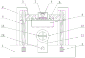
Fig. 1 is a schematic view of the overall structure of the present invention;
fig. 2 is a schematic view of a second motor mounting structure of the present invention;
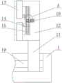
FIG. 3 is a schematic view of the structure of the pipe frame of the present invention;
fig. 4 is a schematic structural diagram of a portion a of fig. 3 according to the present invention.
In the figure: 1-base, 2-fixed frame, 3-first motor, 4-first screw, 5-lifting rod, 6-sliding plate, 7-tooth groove frame, 8-cutting blade, 9-half gear, 10-second motor, 11-fixed plate, 12-pipe frame, 13-clamping block, 14-sliding block, 15-second screw, 16-first bevel gear, 17-second bevel gear, 18-third motor and 19-fixed rod.
Detailed Description
The technical solutions in the embodiments of the present invention will be described clearly and completely with reference to the accompanying drawings in the embodiments of the present invention, and it is obvious that the described embodiments are only some embodiments of the present invention, not all embodiments. Based on the embodiments in the present invention, all other embodiments obtained by a person skilled in the art without creative work belong to the protection scope of the present invention.
Referring to fig. 1-4, the present invention provides a technical solution:
a pipeline cutting device for municipal engineering comprises a base 1, a lifting rod 5 and a pipe frame 12, wherein the top end of the base 1 is fixedly connected with a fixing frame 2, the fixing frame 2 is symmetrically distributed on the left side and the right side of the top end of the base 1, the inner side of the base 1 is fixedly connected with a first motor 3, the first motor 3 is symmetrically distributed on the inner side of the base 1, the tail end of a main shaft of the first motor 3 is fixedly connected with a first screw rod 4, the first screw rod 4 is arranged on the inner side of the fixing frame 2 and is rotationally connected with the fixing frame 2, the first screw rod 4 is fixed through the fixing frame 2, the outer side of the first screw rod 4 is in threaded connection with the lifting rod 5, the lifting rod 5 is in sliding connection with the fixing frame 2, the first screw rod 4 can be driven to slide by the arrangement when rotating, the inner side of the top end of the lifting rod 5 is fixedly connected, the end of the main shaft of the second motor 10 is fixedly connected with a half gear 9, the top end of the lifting rod 5 is connected with a tooth groove frame 7 in a sliding manner, the bottom end of the tooth groove frame 7 is fixedly connected with a sliding plate 6, the sliding plate 6 is connected with the lifting rod 5 in a sliding manner, the bottom end of the sliding plate 6 is fixedly connected with a cutting blade 8, the top end of the base 1 is connected with a fixing plate 11 in a sliding manner, the pipe frame 12 can be fixed on pipelines with different lengths through the sliding of the fixing plate 11, the fixing plate 11 is symmetrically distributed on the front side and the rear side of the base 1, the top end of the fixing plate 11 is fixedly connected with a pipe frame 12, the inner side of the pipe frame 12 is connected with a clamping block 13, the clamping block 13 is symmetrically distributed on the inner side of the pipe frame 12, one end of the clamping block 13 is fixedly connected with a sliding block 14, the sliding block 14, the second screw 15 can drive the sliding block 14 and the clamping block 13 to slide through the rotation of the second screw 15, and one end of the second screw 15, which is rotatably connected with the pipe frame 12, of the second screw 15 is fixedly connected with a first bevel gear 16.
The inner side of the sliding plate 6 is provided with a clamping groove, the inner side of the lifting rod 5 penetrates through the clamping groove and is clamped with the clamping groove, the arrangement ensures that the sliding plate 6 is fixed in the horizontal height through the clamping of the lifting rod 5 and the clamping groove, the sliding plate 6 is prevented from falling off, the half gear 9 is arranged on the inner side of the tooth socket frame 7, the half gear 9 is meshed with a tooth socket in the tooth socket frame 7, the arrangement enables the half gear 9 to drive the tooth socket frame 7 to reciprocate left and right through the meshing of the half gear 9 and the tooth socket frame 7, the inner side of the pipe frame 12 is fixedly connected with a third motor 18, the tail end of a main shaft of the third motor 18 is fixedly connected with a second bevel gear 17, the second bevel gear 17 is meshed with a first bevel gear 16, the arrangement enables the second bevel gear 17 to drive the first bevel gear 16 and a second screw 15 to rotate through the meshing of the first, the inner side of the base 1 is fixedly connected with a fixing rod 19, the outer end face of the fixing rod 19 is connected with the inner side of the fixing plate 11 in a sliding mode, and the arrangement is more stable when the fixing rod 19 enables the fixing plate 11 to slide.
The first motor 3, the second motor 10 and the third motor 18 are YB3-132S-2 motors.
The working process is as follows: the utility model supplies power through an external power supply before using, the device is controlled through an internal control system of the device, when the diameter of the pipeline to be cut is small, the two ends of the pipeline are respectively placed at the inner side of the pipe frame 12, the third motor 18 is started, the third motor 18 drives the second bevel gear 17 to rotate, the second bevel gear 17 drives the second screw 15 to rotate through meshing with the first bevel gear 16, the second screw 15 rotates to drive the slide block 14 to slide, the slide block 14 drives the clamping block 13 to slide towards the center of the pipe frame 12 until the clamping block 13 contacts with the outer wall of the pipeline, the clamping block 13 clamps and fixes the outer wall of the pipeline, when the diameter of the pipeline to be cut is large, the pipeline is sleeved at the outer side of the pipe frame 12, the third motor 18 is started, the third motor 18 drives the second bevel gear 17 to reversely rotate, the second bevel gear 17 drives the second screw 15 to reversely rotate, thereby the slide block 14 and the clamping block 13 slide towards, until the clamping block 13 contacts the inner wall of the pipeline, the clamping block 13 clamps and fixes the inner wall of the pipeline, then the fixing plate 11 is slid, the pipe frame 12 drives the pipeline to slide back and forth above the base 1, the cutting position of the pipeline is adjusted, when the cutting blade 8 is positioned above the position to be cut of the pipeline, the first motor 3 and the second motor 10 are started, the second motor 10 drives the half gear 9 to rotate, when the half gear 9 is meshed with the tooth space on the upper side of the tooth space frame 7, the half gear 9 drives the tooth space frame 7 to slide left, when the half gear 9 is meshed with the tooth space on the lower side of the tooth space frame 7, the half gear 9 drives the tooth space frame 7 to slide right, so that the half gear 9 drives the tooth space frame 7 to reciprocate left and right when rotating, the tooth space frame 7 drives the sliding plate 6 and the cutting blade 8 to reciprocate left and right, the first motor 3 drives the first screw rod 4 to rotate, and drives the lifting rod 5, make lifter 5 drive cutting blade 8 downstream, make cutting blade 8 and pipeline contact, through cutting blade 8 left and right reciprocating motion, can cut the pipeline after making cutting blade 8 and pipeline contact.
Although embodiments of the present invention have been shown and described, it will be appreciated by those skilled in the art that changes, modifications, substitutions and alterations can be made in these embodiments without departing from the principles and spirit of the invention, the scope of which is defined in the appended claims and their equivalents.
Claims (5)
1. The utility model provides a pipeline cutting device for municipal works, includes base (1), lifter (5) and pipe support (12), its characterized in that: the top end of the base (1) is fixedly connected with a fixing frame (2), the fixing frame (2) is symmetrically distributed on the left side and the right side of the top end of the base (1), the inner side of the base (1) is fixedly connected with a first motor (3), the first motor (3) is symmetrically distributed on the inner side of the base (1), the tail end of a main shaft of the first motor (3) is fixedly connected with a first screw (4), the first screw (4) is arranged on the inner side of the fixing frame (2) and is rotationally connected with the fixing frame (2), the outer side of the first screw (4) is in threaded connection with a lifting rod (5), the lifting rod (5) is in sliding connection with the fixing frame (2), the top end inner side of the lifting rod (5) is fixedly connected with a second motor (10), the tail end of the main shaft of the second motor (10) is fixedly connected with a half gear (9), the top end of the lifting rod (5) is in sliding connection, the bottom end of the tooth socket frame (7) is fixedly connected with a sliding plate (6), the sliding plate (6) is connected with the inner side of the lifting rod (5) in a sliding way, the bottom end of the sliding plate (6) is fixedly connected with a cutting blade (8), the inner side of the top end of the base (1) is connected with a fixing plate (11) in a sliding way, the fixed plates (11) are symmetrically distributed on the front side and the rear side of the base (1), the top ends of the fixed plates (11) are fixedly connected with pipe frames (12), the inner side of the pipe frame (12) is connected with clamping blocks (13) in a sliding way, the clamping blocks (13) are symmetrically distributed on the inner side of the pipe frame (12), one end of the clamping block (13) is fixedly connected with a sliding block (14), the sliding block (14) is connected with the pipe frame (12) in a sliding way, the inner side of the sliding block (14) is in threaded connection with a second screw (15), the second screw (15) is in rotary connection with the pipe frame (12), and one end of the second screw (15) is fixedly connected with a first bevel gear (16).
2. The pipe cutting device for municipal engineering according to claim 1, wherein: the inner side of the sliding plate (6) is provided with a clamping groove, and the inner side of the lifting rod (5) penetrates through the clamping groove and is clamped with the clamping groove.
3. The pipe cutting device for municipal engineering according to claim 1, wherein: the half gear (9) is arranged on the inner side of the tooth groove frame (7), and the half gear (9) is meshed with a tooth groove in the tooth groove frame (7).
4. The pipe cutting device for municipal engineering according to claim 1, wherein: the inside fixedly connected with third motor (18) of pipe support (12), the terminal fixedly connected with second bevel gear (17) of main shaft of third motor (18), second bevel gear (17) and first bevel gear (16) meshing.
5. The pipe cutting device for municipal engineering according to claim 1, wherein: the inner side of the base (1) is fixedly connected with a fixing rod (19), and the outer end face of the fixing rod (19) is in sliding connection with the inner side of the fixing plate (11).
Priority Applications (1)
| Application Number | Priority Date | Filing Date | Title |
|---|---|---|---|
| CN201921307421.3U CN210305965U (en) | 2019-08-13 | 2019-08-13 | Pipeline cutting device for municipal works |
Applications Claiming Priority (1)
| Application Number | Priority Date | Filing Date | Title |
|---|---|---|---|
| CN201921307421.3U CN210305965U (en) | 2019-08-13 | 2019-08-13 | Pipeline cutting device for municipal works |
Publications (1)
| Publication Number | Publication Date |
|---|---|
| CN210305965U true CN210305965U (en) | 2020-04-14 |
Family
ID=70129609
Family Applications (1)
| Application Number | Title | Priority Date | Filing Date |
|---|---|---|---|
| CN201921307421.3U Expired - Fee Related CN210305965U (en) | 2019-08-13 | 2019-08-13 | Pipeline cutting device for municipal works |
Country Status (1)
| Country | Link |
|---|---|
| CN (1) | CN210305965U (en) |
Cited By (7)
| Publication number | Priority date | Publication date | Assignee | Title |
|---|---|---|---|---|
| CN111869406A (en) * | 2020-07-14 | 2020-11-03 | 嘉兴花汇红园林有限公司 | A noise-free mechanism of lawnmower for gardens are pruned |
| CN113295854A (en) * | 2021-05-11 | 2021-08-24 | 南通固盛建材有限公司 | Concrete anti-cracking performance testing device |
| CN113681076A (en) * | 2021-09-03 | 2021-11-23 | 安徽宏源钢构有限公司 | Workpiece position correction tool for sawing machine |
| WO2022110252A1 (en) * | 2020-11-30 | 2022-06-02 | 常熟市欧迪管业有限公司 | Titanium tube production apparatus |
| CN114589340A (en) * | 2022-04-18 | 2022-06-07 | 南京鼎久机械装备有限公司 | Mechanical tool with abrasion resistance and corrosion resistance |
| CN114704122A (en) * | 2022-04-19 | 2022-07-05 | 北京首钢建设集团有限公司 | Method for dismantling roof of existing building |
| CN114833527A (en) * | 2021-07-08 | 2022-08-02 | 江苏立霸实业股份有限公司 | Preparation process of VCM film-coated plate |
-
2019
- 2019-08-13 CN CN201921307421.3U patent/CN210305965U/en not_active Expired - Fee Related
Cited By (9)
| Publication number | Priority date | Publication date | Assignee | Title |
|---|---|---|---|---|
| CN111869406A (en) * | 2020-07-14 | 2020-11-03 | 嘉兴花汇红园林有限公司 | A noise-free mechanism of lawnmower for gardens are pruned |
| WO2022110252A1 (en) * | 2020-11-30 | 2022-06-02 | 常熟市欧迪管业有限公司 | Titanium tube production apparatus |
| CN113295854A (en) * | 2021-05-11 | 2021-08-24 | 南通固盛建材有限公司 | Concrete anti-cracking performance testing device |
| CN114833527A (en) * | 2021-07-08 | 2022-08-02 | 江苏立霸实业股份有限公司 | Preparation process of VCM film-coated plate |
| CN114833527B (en) * | 2021-07-08 | 2023-02-24 | 江苏立霸实业股份有限公司 | Cutting and deburring integrated device for VCM film-coated plate production and preparation process |
| CN113681076A (en) * | 2021-09-03 | 2021-11-23 | 安徽宏源钢构有限公司 | Workpiece position correction tool for sawing machine |
| CN114589340A (en) * | 2022-04-18 | 2022-06-07 | 南京鼎久机械装备有限公司 | Mechanical tool with abrasion resistance and corrosion resistance |
| CN114704122A (en) * | 2022-04-19 | 2022-07-05 | 北京首钢建设集团有限公司 | Method for dismantling roof of existing building |
| CN114704122B (en) * | 2022-04-19 | 2023-12-01 | 北京首钢建设集团有限公司 | Method for dismantling roof of existing building |
Similar Documents
| Publication | Publication Date | Title |
|---|---|---|
| CN210305965U (en) | Pipeline cutting device for municipal works | |
| CN109095761B (en) | Mechanical cutting device is used in glass pipe processing | |
| CN211010166U (en) | Pipeline installation locating support for water conservancy and hydropower | |
| CN212218114U (en) | Pipeline rust cleaning device for hydraulic engineering | |
| CN212286057U (en) | Automatic rotary type cutting device is used in pipeline under pressure pipe fitting production | |
| CN218081217U (en) | Fixing and aligning machine for water pipeline construction | |
| CN215432348U (en) | Hastelloy pipeline welding device convenient to install | |
| CN217344270U (en) | Steel pipe welding fixture for steel structure building | |
| CN213946187U (en) | Pipe clamp with auxiliary positioning mechanism | |
| CN211219471U (en) | Elbow joint clamping device for water conservancy construction | |
| CN211104200U (en) | Cutting device for pipeline processing | |
| CN215393311U (en) | Electric welding equipment for metal tube processing | |
| CN110666545B (en) | Axial cutting device of nonrust steel pipe | |
| CN209738052U (en) | Fixing device for ceramic machining cutting | |
| CN209954261U (en) | Mechanical fixture for cutting steel pipe | |
| CN210414732U (en) | Cutting device is used in rubber tube production | |
| CN211804936U (en) | Power pipeline cutting device | |
| CN219724773U (en) | Cutting device with clamping structure | |
| CN218364327U (en) | Pipe fitting adds clamping apparatus | |
| CN214291579U (en) | Automatic straight pipe butt welding machine for boiler | |
| CN220488471U (en) | Butt joint traction device for pipeline machining | |
| CN212121869U (en) | Nonrust steel pipe groove cutting machine | |
| CN217833370U (en) | Clamping mechanism for pipeline piece and pipeline machining | |
| CN216327949U (en) | Pipeline interfacing apparatus is used in hydraulic engineering construction | |
| CN219787241U (en) | A quick welding set for construction of water conservancy pipeline |
Legal Events
| Date | Code | Title | Description |
|---|---|---|---|
| GR01 | Patent grant | ||
| GR01 | Patent grant | ||
| CF01 | Termination of patent right due to non-payment of annual fee | ||
| CF01 | Termination of patent right due to non-payment of annual fee |
Granted publication date: 20200414 Termination date: 20210813 |