CN210304843U - Belt cleaning device is used in processing of zinc alloy button - Google Patents
Belt cleaning device is used in processing of zinc alloy button Download PDFInfo
- Publication number
- CN210304843U CN210304843U CN201920914495.7U CN201920914495U CN210304843U CN 210304843 U CN210304843 U CN 210304843U CN 201920914495 U CN201920914495 U CN 201920914495U CN 210304843 U CN210304843 U CN 210304843U
- Authority
- CN
- China
- Prior art keywords
- button
- cleaning box
- cleaning
- box
- box cover
- Prior art date
- Legal status (The legal status is an assumption and is not a legal conclusion. Google has not performed a legal analysis and makes no representation as to the accuracy of the status listed.)
- Expired - Fee Related
Links
Images


Abstract
The utility model discloses a belt cleaning device is used in processing of zinc alloy button, including bottom plate, ultrasonic device, washing case, ultrasonic device is installed to the bottom plate upper end, and ultrasonic device is located and washs the case left, washs the incasement bottom and is provided with ultrasonic emission device, and the water tank is installed to the bottom plate upper end, and the water tank is located and washs case the place ahead, has the cavity in the water tank, is equipped with the water pump in the cavity, and drinking-water pipe one end is connected to water pump one end, and the drinking-water pipe other end passes the cavity, and the raceway one end is connected to the water pump other end, and the raceway other end passes the water tank upper end and connects and wash case front end upper portion, the utility model discloses a water extraction in the water tank of water pump to wasing the.
Description
Technical Field
The utility model relates to a belt cleaning device specifically is a belt cleaning device is used in processing of zinc alloy button.
Background
Zinc alloys can be classified into cast zinc alloys and wrought zinc alloys according to the manufacturing process. The main additive elements of the zinc alloy are aluminum, copper, magnesium and the like. The zinc alloy can be divided into two types of deformation and casting zinc alloy according to the processing technology. The cast zinc alloy has good fluidity and corrosion resistance, and is suitable for die-casting instruments, automobile part shells and the like.
Zinc alloy is when preparation button, and the button processing can be adhered to after accomplishing has the dust, needs wash it, and belt cleaning device's cleaning performance is poor among the prior art, and groove can not wash, does not possess the stoving function simultaneously. Therefore, the cleaning device for processing the zinc alloy button is provided by the technical personnel in the field so as to solve the problems in the background technology.
Disclosure of Invention
An object of the utility model is to provide a belt cleaning device is used in processing of zinc alloy button to solve the problem that proposes among the above-mentioned background art.
In order to achieve the above object, the utility model provides a following technical scheme:
a cleaning device for processing zinc alloy buttons comprises a bottom plate, an ultrasonic device and a cleaning box, wherein the upper end of the bottom plate is provided with the cleaning box, the upper end of the cleaning box is provided with a cleaning box cover, a frame is arranged in the cleaning box, the right end of the frame is provided with a connecting rod, the right end of the connecting rod is rotatably connected with a rotating bearing, the right end of the rotating bearing is fixedly connected to the right wall in the cleaning box, the left end of the cleaning box is provided with a motor shell, a motor is arranged in the motor shell, the right end of the motor penetrates through the left end of the cleaning box and;
the button box is arranged in the frame, fixed blocks are arranged at the left end and the right end of the button box corresponding to the positions of the threaded rods, through holes are formed in the positions, corresponding to the threaded rods, of the fixed blocks, the inner diameter of each through hole is equal to the diameter of the threaded rod, nuts are sleeved on the threaded rods and are located above the fixed blocks, a button box cover is arranged at the upper end of the button box, hinges I are symmetrically arranged at the left end and the right end of the rear end of the button box cover, the button box cover is rotatably connected with the button box through the hinges I, a clamping lock I is arranged at the front end of the button box cover, the button box cover is fixedly connected to;
ultrasonic device is installed to the bottom plate upper end, and ultrasonic device is located washs the case left, washs incasement bottom and is provided with ultrasonic emission device, and the water tank is installed to the bottom plate upper end, and the water tank is located washs case the place ahead, has the cavity in the water tank, is equipped with the water pump in the cavity, and drinking-water pipe one end is connected to water pump one end, and the drinking-water pipe other end passes the cavity, and raceway one end is connected to the water pump other end, and the raceway other end passes the water tank upper.
In operation, open the button case lid and fall the button to the button incasement, lock the button case lid through the kayser, the rethread through-hole overlaps the fixed block on the threaded rod of way, then tighten up the nut, the water pump work is through the extraction of the water of drinking-water pipe in with the water tank, the rethread raceway with water transmission to wash the incasement flood the button case, the size of button case and button case lid fretwork department is littleer than the button, so the button can not drop out from the fretwork department, hydroenergy infiltration enters simultaneously, ultrasonic wave device work takes place the sound wave through ultrasonic emission device, wash button incasement button, motor work drives the frame through connecting rod and rolling bearing and rotates, the frame rotates and drives the button case and rotates, make the button upset of button incasement.
As a further aspect of the present invention: the heat dissipation shell is installed to the washing case right-hand member, and the heat dissipation shell is located the button case top, is provided with the air heater in the heat dissipation shell, and the blowing pipe is connected to the air heater left end, and the blowing pipe passes and washs the case right-hand member and connects the blowing head, and blowing head fixed connection is at the right wall in the washing case.
In work, the hot air blower blows hot air to the blowing head through the blowing pipe, and the blowing head blows air to the button box, so that buttons in the button box are quickly dried.
As a further aspect of the present invention: the lower part of the right end of the cleaning box is connected with a drain pipe, and a water valve is sleeved on the drain pipe.
In operation, the water valve is opened, and the water in the cleaning box flows out through the drain pipe.
As a further aspect of the present invention: the left and right symmetry of the front end of the cleaning box cover is provided with a second hinge, the cleaning box cover is rotatably connected with the cleaning box through the second hinge, the rear end of the cleaning box cover is provided with a second clamping lock, and the cleaning box cover is fixedly connected to the upper end of the cleaning box through the second clamping lock.
In the work, open the cleaning case lid and take out the button case, conveniently pour the button.
As a further aspect of the present invention: the lower end of the motor is provided with a first damping pad, and the lower end of the air heater is provided with a second damping pad.
During work, vibration generated when the motor and the air heater work is effectively reduced through the first damping pad and the second damping pad.
As a further aspect of the present invention: the supporting legs are symmetrically installed at the front and the back of the lower end of the bottom plate, and universal wheels are arranged at the lower ends of the supporting legs.
During operation, the device is provided with mobility through the universal wheels.
Compared with the prior art, the beneficial effects of the utility model are that:
the utility model discloses an ultrasonic emission device takes place the sound wave, wash button incasement button, can effectual clearance button groove's dust, motor work drives the frame and rotates, the frame rotates and drives the button case and rotates, make the button upset of button incasement, accelerate and wash speed, wash and open the water valve after finishing, wash the water of incasement and pass through the drain pipe and flow, air heater work blows hot-blast to the head of blowing through the blowing pipe, the head of blowing is bloied to the button case, motor work drives the upset of button case, make the button fast drying of button incasement, and the time is saved, and the work efficiency is improved.
Drawings
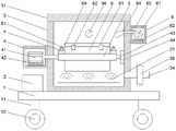
Fig. 1 is a schematic structural diagram of a cleaning device for processing a zinc alloy button.
Fig. 2 is a schematic structural diagram of a water tank in a cleaning device for processing zinc alloy buttons.
Fig. 3 is a perspective view of a frame in the cleaning device for processing the zinc alloy button.
Fig. 4 is a perspective view of a button box in the cleaning device for processing zinc alloy buttons.
In the figure: 1. a base plate; 11. supporting legs; 12. a universal wheel; 2. an ultrasonic device; 21. an ultrasonic wave emitting device; 3. a cleaning tank; 31. cleaning the box cover; 32. a second hinge; 33. locking a second lock; 34. a drain pipe; 35. a water valve; 4. a motor housing; 41. a motor; 42. a first shock absorption pad; 43. a connecting rod; 44. a rotating bearing; 5. a frame; 51. a threaded rod; 6. a button box; 61. a button box cover; 62. a first hinge; 63. locking a first lock; 64. a fixed block; 65. a through hole; 7. a nut; 8. a heat dissipation housing; 81. a hot air blower; 82. a second damping pad; 83. a blowpipe; 84. a blowing head; 9. a water tank; 91. a cavity; 92. a water pump; 93. a water pumping pipe; 94. a water delivery pipe.
Detailed Description
The technical solutions in the embodiments of the present invention will be described clearly and completely with reference to the accompanying drawings in the embodiments of the present invention, and it is obvious that the described embodiments are only some embodiments of the present invention, not all embodiments. Based on the embodiments in the present invention, all other embodiments obtained by a person skilled in the art without creative work belong to the protection scope of the present invention.
Please refer to fig. 1-4, in the embodiment of the present invention, a cleaning device for processing a zinc alloy button includes a bottom plate 1, an ultrasonic device 2, a cleaning box 3, wherein the cleaning box 3 is installed at the upper end of the bottom plate 1, a cleaning box cover 31 is installed at the upper end of the cleaning box 3, a frame 5 is installed in the cleaning box 3, a connecting rod 43 is installed at the right end of the frame 5, the right end of the connecting rod 43 is rotatably connected with a rotating bearing 44, the right end of the rotating bearing 44 is fixedly connected to the right wall in the cleaning box 3, a motor housing 4 is installed at the left end of the cleaning box 3, a motor 41 is installed in the motor housing 4, the right end of the motor 41 passes through the left end of the cleaning box 3;
the button box 6 is arranged in the frame 5, the positions of the left end and the right end of the button box 6, which correspond to the threaded rods 51, are provided with fixing blocks 64, the positions of the fixing blocks 64, which correspond to the threaded rods 51, are provided with through holes 65, the inner diameter of each through hole 65 is the same as the diameter of each threaded rod 51, the threaded rods 51 are sleeved with nuts 7, the nuts 7 are positioned above the fixing blocks 64, the upper end of the button box 6 is provided with a button box cover 61, the rear end of the button box cover 61 is bilaterally symmetrically provided with hinges I62, the button box cover 61 is rotatably connected with the button box 6 through the hinges I62, the front end of the button box cover 61 is provided with a clamping lock I63, the button box cover 61 is fixedly connected to the upper;
In operation, open button case lid 61 and fall the button to in button case 6, pin button case lid 61 through kayser 63, rethread through-hole 65 overlaps fixed block 64 on way threaded rod 51, then screw up nut 7, water pump 92 work is through the water extraction of drinking-water pipe 93 in with water tank 9, rethread raceway 94 with water transmission submerge button case 6 to flooding in cleaning box 3, the size of button case 6 and button case lid 61 fretwork department is less than the button, so the button can not drop out from the fretwork department, hydroenergy permeates into simultaneously, ultrasonic device 2 works and takes place the sound wave through ultrasonic emission device 21, wash button 6 interior button, connecting rod 43 and rolling bearing 44 are passed through in the work of motor 41 and drive frame 5 and rotate, frame 5 rotates and drives button case 6 and rotates, make the button upset in the button case 6.
The right end of the cleaning box 3 is provided with a heat dissipation shell 8, the heat dissipation shell 8 is located above the button box 6, an air heater 81 is arranged in the heat dissipation shell 8, the left end of the air heater 81 is connected with a blowing pipe 83, the blowing pipe 83 penetrates through the right end of the cleaning box 3 to be connected with a blowing head 84, and the blowing head 84 is fixedly connected to the right wall of the cleaning box 3.
In operation, the hot air blower 81 blows hot air to the blowing head 84 through the blowing pipe 83, and the blowing head 84 blows air to the button box 6, so that the buttons in the button box 6 are dried quickly.
The lower part of the right end of the cleaning box 3 is connected with a drainage pipe 34, and a water valve 35 is sleeved on the drainage pipe 34.
In operation, the water valve 35 is opened and the water in the washing tank 3 flows out through the drain pipe 34.
Two hinges 32 are symmetrically arranged at the left and right sides of the front end of the cleaning box cover 31, the cleaning box cover 31 is rotatably connected with the cleaning box 3 through the two hinges 32, two locking devices 33 are arranged at the rear end of the cleaning box cover 31, and the cleaning box cover 31 is fixedly connected to the upper end of the cleaning box 3 through the two locking devices 33.
In operation, the cleaning box cover 31 is opened to take out the button box 6, so that the buttons can be conveniently taken out.
The lower end of the motor 41 is provided with a first shock absorption pad 42, and the lower end of the hot air blower 81 is provided with a second shock absorption pad 82.
In operation, the first shock absorbing pad 42 and the second shock absorbing pad 82 effectively reduce the vibration generated during the operation of the motor 41 and the hot air blower 81.
Supporting legs 11 are symmetrically installed at the front and the rear of the lower end of the bottom plate 1, and universal wheels 12 are arranged at the lower ends of the supporting legs 11.
During operation, the device is made mobile by the universal wheels 12.
The utility model discloses a theory of operation is: the button box cover 61 is opened to pour the buttons into the button box 6, the button box cover 61 is locked through the first clamping lock 63, the cleaning box cover 31 is opened to place the button box 6 into the frame 5, the fixing block 64 is sleeved on the threaded rod 51 through the through hole 65, then the nut 7 is screwed, the water pump 92 works to pump the water in the water tank 9 through the water pumping pipe 93, the water is transmitted into the cleaning box 3 through the water conveying pipe 94 to submerge the button box 6, the size of the hollowed part of the button box 6 and the button box cover 61 is smaller than that of the buttons, so the buttons cannot fall out from the hollowed part, meanwhile, water can permeate into the water, the ultrasonic device 2 works to generate sound waves through the ultrasonic transmitting device 21 to clean the buttons in the button box 6, the motor 41 works to drive the frame 5 to rotate through the connecting rod 43 and the rotating bearing 44, the frame 5 rotates to drive the button box 6 to rotate, the button box 6 to turn over, after the cleaning, the water valve 35 is opened, water in the cleaning box 3 flows out through the drain pipe 34, the hot air blower 81 blows hot air to the blowing head 84 through the blowing pipe 83, the blowing head 84 blows air to the button box 6, and the motor 41 drives the button box 6 to turn over to dry the buttons in the button box 6 quickly.
The above, only be the concrete implementation of the preferred embodiment of the present invention, but the protection scope of the present invention is not limited thereto, and any person skilled in the art is in the technical scope of the present invention, according to the technical solution of the present invention and the utility model, the concept of which is equivalent to replace or change, should be covered within the protection scope of the present invention.
Claims (6)
1. A cleaning device for processing zinc alloy buttons comprises a bottom plate (1), an ultrasonic device (2) and a cleaning box (3), and is characterized in that the cleaning box (3) is installed at the upper end of the bottom plate (1), a cleaning box cover (31) is installed at the upper end of the cleaning box (3), a frame (5) is arranged in the cleaning box (3), a connecting rod (43) is installed at the right end of the frame (5), the right end of the connecting rod (43) is rotatably connected with a rotating bearing (44), the right end of the rotating bearing (44) is fixedly connected to the right wall in the cleaning box (3), a motor shell (4) is arranged at the left end of the cleaning box (3), a motor (41) is arranged in the motor shell (4), the right end of the motor (41) penetrates through the left end of the cleaning box (3) and is fixedly connected with the left end;
the button box is characterized in that a button box (6) is arranged in the frame (5), fixing blocks (64) are arranged at the left end and the right end of the button box (6) corresponding to the positions of the threaded rods (51), through holes (65) are formed in the positions of the fixing blocks (64) corresponding to the positions of the threaded rods (51), the inner diameters of the through holes (65) are the same as the diameter of the threaded rods (51), nuts (7) are sleeved on the threaded rods (51), the nuts (7) are located above the fixing blocks (64), a button box cover (61) is arranged at the upper end of the button box (6), hinge units (62) are symmetrically arranged at the left end and the right end of the button box cover (61), the button box cover (61) is rotatably connected with the button box (6) through the hinge units (62), a clamping lock unit (63) is arranged at the front end of the button box cover (61), the button box cover (61) is fixedly connected, the upper end of the button box cover (61) is in a hollow shape;
ultrasonic device (2) are installed to bottom plate (1) upper end, and ultrasonic device (2) are located and wash case (3) left, it is provided with ultrasonic emission device (21) to wash bottom in case (3), water tank (9) are installed to bottom plate (1) upper end, and water tank (9) are located and wash case (3) the place ahead, there is cavity (91) in water tank (9), be equipped with water pump (92) in cavity (91), drinking-water pipe (93) one end is connected to water pump (92) one end, drinking-water pipe (93) other end passes cavity (91), raceway (94) one end is connected to the water pump (92) other end, raceway (94) other end passes water tank (9) upper end and connects and washs case (3) front end upper portion.
2. The cleaning device for processing the zinc alloy button as recited in claim 1, characterized in that a heat dissipation shell (8) is installed at the right end of the cleaning box (3), the heat dissipation shell (8) is located above the button box (6), an air heater (81) is arranged in the heat dissipation shell (8), the left end of the air heater (81) is connected with a blowing pipe (83), the blowing pipe (83) penetrates through the right end of the cleaning box (3) to be connected with an air blowing head (84), and the air blowing head (84) is fixedly connected to the right wall in the cleaning box (3).
3. The cleaning device for processing the zinc alloy button as recited in claim 1, wherein a drain pipe (34) is connected to the lower part of the right end of the cleaning box (3), and a water valve (35) is sleeved on the drain pipe (34).
4. The cleaning device for processing the zinc alloy buttons as claimed in claim 1, wherein the front end of the cleaning box cover (31) is symmetrically provided with a second hinge (32) at left and right sides, the cleaning box cover (31) is rotatably connected with the cleaning box (3) through the second hinge (32), the rear end of the cleaning box cover (31) is provided with a second latch (33), and the cleaning box cover (31) is fixedly connected to the upper end of the cleaning box (3) through the second latch (33).
5. The cleaning device for processing the zinc alloy buttons as claimed in claim 1, wherein a first shock absorption pad (42) is mounted at the lower end of the motor (41), and a second shock absorption pad (82) is mounted at the lower end of the hot air blower (81).
6. The cleaning device for processing the zinc alloy button as recited in claim 1, characterized in that the lower end of the bottom plate (1) is provided with support legs (11) symmetrically in front and back, and the lower ends of the support legs (11) are provided with universal wheels (12).
Priority Applications (1)
| Application Number | Priority Date | Filing Date | Title |
|---|---|---|---|
| CN201920914495.7U CN210304843U (en) | 2019-06-18 | 2019-06-18 | Belt cleaning device is used in processing of zinc alloy button |
Applications Claiming Priority (1)
| Application Number | Priority Date | Filing Date | Title |
|---|---|---|---|
| CN201920914495.7U CN210304843U (en) | 2019-06-18 | 2019-06-18 | Belt cleaning device is used in processing of zinc alloy button |
Publications (1)
| Publication Number | Publication Date |
|---|---|
| CN210304843U true CN210304843U (en) | 2020-04-14 |
Family
ID=70144599
Family Applications (1)
| Application Number | Title | Priority Date | Filing Date |
|---|---|---|---|
| CN201920914495.7U Expired - Fee Related CN210304843U (en) | 2019-06-18 | 2019-06-18 | Belt cleaning device is used in processing of zinc alloy button |
Country Status (1)
| Country | Link |
|---|---|
| CN (1) | CN210304843U (en) |
Cited By (1)
| Publication number | Priority date | Publication date | Assignee | Title |
|---|---|---|---|---|
| CN112474453A (en) * | 2020-11-03 | 2021-03-12 | 温州素萨纺织品有限公司 | Button cleaning device with recyclable cleaning water |
-
2019
- 2019-06-18 CN CN201920914495.7U patent/CN210304843U/en not_active Expired - Fee Related
Cited By (2)
| Publication number | Priority date | Publication date | Assignee | Title |
|---|---|---|---|---|
| CN112474453A (en) * | 2020-11-03 | 2021-03-12 | 温州素萨纺织品有限公司 | Button cleaning device with recyclable cleaning water |
| CN112474453B (en) * | 2020-11-03 | 2021-11-19 | 黄鲁进 | Button cleaning device with recyclable cleaning water |
Similar Documents
| Publication | Publication Date | Title |
|---|---|---|
| CN210304843U (en) | Belt cleaning device is used in processing of zinc alloy button | |
| CN211267554U (en) | Internet-based heat dissipation device for storage equipment | |
| CN208522292U (en) | A kind of powering shelf of rain-proof heat dissipation | |
| CN209775283U (en) | Cleaning equipment is used in mould production | |
| CN216087360U (en) | Server cooling device for preventing uneven heat dissipation | |
| CN210731857U (en) | Bearing processing heat abstractor | |
| CN211660740U (en) | Quick cooling mechanism of hot rolling mill | |
| CN212617447U (en) | Security protection type surveillance camera head | |
| CN111651022A (en) | Heat radiator for computer machine case | |
| CN212600572U (en) | Numerical control machine tool with protection structure | |
| CN206917756U (en) | A kind of high intensity crankcase of bottom wind-guiding | |
| CN213548179U (en) | Network communication equipment heat abstractor | |
| CN214095291U (en) | Drying device for hardware processing | |
| CN216721876U (en) | Speed reducer shell convenient to heat dissipation | |
| CN214592664U (en) | Mechanical electronic controller suitable for mechanical engineering | |
| CN214698498U (en) | High temperature resistant fan bearing cooling device | |
| CN213185725U (en) | Servo motor with better heat dissipation function | |
| CN219442698U (en) | Radiator cleaning device | |
| CN211139467U (en) | Environment-friendly resin machine-formed efficient noise-reduction engine hood assembly | |
| CN213797671U (en) | Hot drying device for CPP film production | |
| CN211331280U (en) | Heat abstractor for metallurgical equipment | |
| CN213396151U (en) | Flow guide device for air cooling equipment | |
| CN219309783U (en) | Air pipe flange machine with cooling device | |
| CN216310679U (en) | Computer machine case heat dissipation mechanism | |
| CN215090241U (en) | Cooling device for aluminum alloy calendering |
Legal Events
| Date | Code | Title | Description |
|---|---|---|---|
| GR01 | Patent grant | ||
| GR01 | Patent grant | ||
| CF01 | Termination of patent right due to non-payment of annual fee |
Granted publication date: 20200414 Termination date: 20210618 |
|
| CF01 | Termination of patent right due to non-payment of annual fee |