CN210300131U - Storage cabinet for storing paper documents - Google Patents
Storage cabinet for storing paper documents Download PDFInfo
- Publication number
- CN210300131U CN210300131U CN201920606555.9U CN201920606555U CN210300131U CN 210300131 U CN210300131 U CN 210300131U CN 201920606555 U CN201920606555 U CN 201920606555U CN 210300131 U CN210300131 U CN 210300131U
- Authority
- CN
- China
- Prior art keywords
- drawer
- cabinet body
- cabinet
- storage
- paper document
- Prior art date
- Legal status (The legal status is an assumption and is not a legal conclusion. Google has not performed a legal analysis and makes no representation as to the accuracy of the status listed.)
- Active
Links
Images


Landscapes
- Drawers Of Furniture (AREA)
Abstract
The utility model discloses a storage cabinet for storing paper documents, which comprises a cabinet body, wherein a plurality of drawer cavities with openings at the front ends are arranged on the cabinet body, drawers are arranged in the drawer cavities, and the bottoms of the drawers are arranged in the drawer cavities through drawer transmission mechanisms; the middle of the front end of the cabinet body is provided with a controller, the upper end of the controller is provided with a mounting rod which is fixed on the cabinet body and has a circular forward convex section, and two sides of the cabinet body are respectively and transversely provided with a mounting rod; and the mounting rods on the left side and the right side of the cabinet body are provided with multifunctional plates. The utility model relates to a rationally, simple structure for the storage of paper document, the design has the several drawer, so that the classification of various data is deposited, through reasonable design drawer drive mechanism, makes its drawer open and shut and can realize automatically, no longer opens and shuts through the manual work, makes its user more convenient, and reasonable the establishing multifunctional board simultaneously, this multifunctional board can regard as the desktop placing object article to use, also can regard as the show board to use.
Description
Technical Field
The utility model relates to a data cabinet specifically says to a cabinet for paper document storage.
Background
A file storage cabinet belongs to office furniture series. Namely, the cabinet is used for storing the archival data; is a relatively traditional harness for preserving files, which is usually a case with a cover and a cabinet with a door. Generally made of wood or metal, or made into combined type, separated into boxes and stacked into a cabinet. The dust-proof and dust-proof device has the advantages that the dust-proof and dust-proof device can effectively prevent invasion of other harmful substances, and is convenient to carry and move; the defects are high cost, large occupied effective space of the storehouse and small accumulated amount of unit area. Such as ancient stone rooms, dragon cabinets, etc.; modern file cabinets are more diversified in form; the traditional storage cabinet has a simple structure and a single function.
The utility model with the patent number of CN201720028625.8 is found through retrieval and discloses a multifunctional information technology data storage cabinet, which comprises an observation window, a control box, a handle, a cabinet body, an internal structure, a clapboard, a bottom wheel and a cabinet door, wherein the observation window is arranged on the front surface of the cabinet body; the control box is arranged at the left upper part of the cabinet body; the handles are arranged on the left side and the right side of the cabinet door; the internal structure install in the inside of the cabinet body, this cabinet structure is complicated to the function is single.
SUMMERY OF THE UTILITY MODEL
In order to overcome the above-mentioned not enough, the utility model provides a reasonable in design, simple structure, convenient to use is used for the cabinet of paper document storage, the utility model discloses the design has the several drawer to the classification of various data is deposited, through reasonable design drawer drive mechanism, makes its drawer open and shut and can realize the automation, no longer opens and shuts through the manual work, makes its user more convenient, and reasonable the multifunctional plate of establishing simultaneously, this multifunctional plate can regard as desktop placing object article to use, also can regard as the show board to use.
The utility model discloses a realize like this, construct a cabinet for paper document storage, including the cabinet body, set up several front end open-ended drawer chamber on this cabinet body to install drawer, its characterized in that in this drawer chamber: the bottom of the drawer is arranged in the drawer cavity through a drawer transmission mechanism;
the middle of the front end of the cabinet body is provided with a controller, the upper end of the controller is provided with a mounting rod which is fixed on the cabinet body and has a circular forward convex section, and two sides of the cabinet body are respectively and transversely provided with a mounting rod;
and the mounting rods on the left side and the right side of the cabinet body are provided with multifunctional plates.
Preferably, the drawer transmission mechanism comprises a motor, a lead screw and a moving block, the lead screw penetrates through the moving block and is mounted at the bottom of the drawer cavity through a lead screw mounting seat, the moving block is fixedly connected to the bottom of the drawer, the motor is mounted at the bottom of the drawer cavity and is connected with the lead screw, the lead screw is driven through rotation of the motor, the drawer is driven to move through rotation of the lead screw, and meanwhile the motor is connected with the controller.
Preferably, the two sides of the drawer are fixedly provided with guide rods which protrude outwards and have semicircular sections, and the guide rods are matched with guide grooves formed in the side surfaces of the drawer cavity.
Preferably, the front end of the drawer is provided with a card box convenient for placing an information card.
Preferably, the inner side of the upper end of the multifunctional plate is provided with an arc-shaped groove buckled on the mounting rod, and the inner side of the multifunctional plate is provided with a support frame capable of being folded.
Preferably, the support frame comprises an upper support and a lower support, wherein the upper end of the upper support is mounted on the multifunctional plate in a hinged manner through a pin shaft, the lower end of the upper support is connected with the lower support in a hinged manner through a rotating shaft, and the width of the lower support is smaller than that of the upper support;
the pivot follows the lower carriage and rotates to fixedly being provided with the stopper in this pivot, this stopper matches with the little stopper that fixedly sets up in the upper bracket outside, realizes spacing and support after the lower carriage expandes through stopper and little stopper.
Preferably, the upper bracket is provided with a containing groove for placing the folded lower bracket.
Preferably, the monitor is installed at the upper end of the cabinet body through the mounting frame and connected with the computer.
Preferably, the controller is a computer.
The storage cabinet is mounted for use in a manner,
firstly, the storage cabinet is placed in an archive room or a conference room, a drawer needing to be opened or closed is recorded into a computer according to the requirement of a user,
the motor works through the command of the computer, the lead screw is driven to rotate through the rotation of the motor, the moving block is driven to move by the rotation of the lead screw, and the drawer is driven to move by the moving block, so that the opening and closing of the drawer are realized, and the storage of data is facilitated;
after finishing the data storage, the user can selectively use the multifunctional board,
when the multifunctional board is used as a display board, the support is folded, the multifunctional board is installed through the installation rod in front of the cabinet body or the installation rod on the side face of the cabinet body, the surface of the multifunctional board faces outwards, and workers can fill lifting information on the surface of the multifunctional board;
when the multifunctional board is used for placing articles as the desktop, the support frame is unfolded, the lower support and the upper support are unfolded, so that the lower support and the upper support are arranged on a plane, the lower support is in contact with the cabinet body as a support, the multifunctional board can be stably placed, the limit blocks and the small limit blocks are attached to each other in the process, and the attaching place serves as a fulcrum, so that the multifunctional board is more stable.
The utility model discloses following beneficial effect has:
the utility model relates to a storage cabinet for storing paper documents, which is designed with a plurality of drawers to facilitate the classified storage of various data, and the drawer transmission mechanism is reasonably designed to ensure that the opening and closing of the drawers can be realized automatically, and the drawers are not opened and closed manually any more, so that the users can more conveniently use the storage cabinet;
the utility model can be placed on the rear wall of a meeting room, and can be used as a display board while storing files, so that a user can fill lifting information in the display board, and the multifunctional board is convenient to mount and dismount and can be used according to actual conditions;
the multifunctional plate can also be used as a desktop for placing articles, is used for placing quality or other articles, and is simple to use and convenient to install;
the mounting bracket is reasonably installed on two sides of the cabinet body and the front end face, the mounting bracket is convex, the cross section is circular, the mounting bracket is matched with the arc-shaped groove of the multifunctional plate, the multifunctional mounting plate is convenient to install, and the multifunctional mounting plate can rotate on the mounting bracket, so that the multifunctional mounting plate is more convenient to use.
The inner side of the multifunctional plate is reasonably provided with a support frame which can be folded, the support frame passes through an upper support and a lower structure, the upper support and the lower support are connected in a hinged mode and can rotate, so that the installation and folding are very convenient, meanwhile, the upper support and the lower support are connected through a rotating shaft, the rotating shaft rotates along with the lower support, a limit block is arranged on the rotating shaft, the limit block is matched with a small limit block fixedly arranged on the outer side surface of the upper support, when the upper support and the lower support are unfolded, the limit block is attached to the small limit block to form a supporting fulcrum, and the lower support cannot play a supporting role due to an overlarge rotating angle;
meanwhile, the utility model is provided with a monitor at the upper end of the cabinet body, and the condition of the front end of the storage cabinet can be monitored by the monitor;
reasonable design drawer has drive mechanism in this drawer bottom design, and this drive mechanism can drive the drawer and remove to realize opening or closing of drawer, when using, the motor is at external power supply energy supply, and through computer control, the motor during operation drives the lead screw and rotates, and the rotation of lead screw drives the removal piece and removes, and the removal of drawer is driven again to the movable block, and this transmission is steady, has realized opening and shutting of drawer.
The utility model discloses the structure is ingenious, convenient to use, and easy manufacturing, low cost, excellent in use effect, application range is also very wide, is fit for using widely.
Drawings
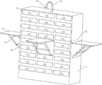
Fig. 1 is a perspective view of the present invention;
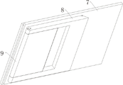
FIG. 2 is a schematic view of the multi-function plate of the present invention;
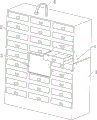
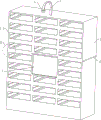
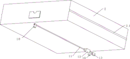
fig. 3-4 are perspective views of the cabinet body of the present invention after the drawer is installed;
fig. 5 is a perspective view of the cabinet body of the present invention;
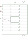
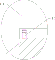
fig. 6 is a front view of the cabinet body of the present invention;
FIG. 7 is a cross-sectional view of C-C of FIG. 6;
FIG. 8 is an enlarged partial schematic view of D of FIG. 4;
FIG. 9 is an enlarged partial schematic view of B in FIG. 5;
FIG. 10 is an enlarged partial schematic view of M of FIG. 7;
FIG. 11 is a perspective view of the drawer of the present invention;
FIG. 12 is a front view of the drawer of the present invention;
figure 13 is a side view of a drawer of the present invention;
fig. 14-15 are schematic views of the multi-function plate support frame of the present invention;
fig. 16 is a perspective view of the multifunctional plate support frame of the present invention after being folded;
fig. 17 is a perspective view of the support frame of the present invention after being folded;
FIG. 18 is an enlarged partial schematic view of A in FIG. 15;
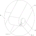
fig. 19 is a partially enlarged schematic view of a in fig. 2.
Detailed Description
The present invention will be described in detail with reference to the accompanying drawings 1-19, wherein the technical solutions in the embodiments of the present invention are clearly and completely described, and it is obvious that the described embodiments are only some embodiments of the present invention, not all embodiments. Based on the embodiments in the present invention, all other embodiments obtained by a person skilled in the art without creative work belong to the protection scope of the present invention.
As shown in fig. 1-19, the utility model provides a storage cabinet for paper document storage, including the cabinet body 1, set up several front end open-ended drawer chamber 1.1 on this cabinet body to install drawer 2 in this drawer chamber 1.1, its characterized in that: the bottom of the drawer 2 is arranged in the drawer cavity 1.1 through a drawer transmission mechanism;
the middle of the front end of the cabinet body 1 is provided with a controller 3, the upper end of the controller 3 is provided with a mounting rod 6 which is fixed on the cabinet body 1 and has a circular forward convex section, and two sides of the cabinet body 1 are respectively and transversely provided with a mounting rod 6;
and the multifunctional plates 7 are arranged on the mounting rods at the left side and the right side of the cabinet body.
In this embodiment, the drawer transmission mechanism includes a motor 13, a lead screw 11 and a moving block 12, the lead screw 11 runs through the moving block and is installed at the bottom of the drawer cavity 1.1 through a lead screw installation seat, the moving block 12 is fixedly connected to the bottom of the drawer 2, the motor 13 is installed at the bottom of the drawer cavity and is connected with the lead screw, the lead screw is driven through the rotation of the motor, the drawer is driven to move through the rotation of the lead screw, and meanwhile, the motor 13 is connected with the controller 3.
In the embodiment, the drawer 2 is fixedly provided with guide rods 2.1 which are convex and have semicircular sections at two sides, and the guide rods 2.1 are matched with guide grooves 1.2 formed in the side surfaces of the drawer cavity 1.1.
In this embodiment, the front end of the drawer 2 is provided with a card box 2.2 for placing information cards.
In this embodiment, the inner side of the upper end of the multifunctional plate 7 is provided with an arc-shaped groove buckled on the mounting rod 6, and the inner side of the multifunctional plate 6 is provided with a support frame capable of being folded.
In this embodiment, the support frame comprises an upper support 8 and a lower support 9, wherein the upper end of the upper support is mounted on the multifunctional plate 7 in a hinged manner through a pin shaft, the lower end of the upper support is connected with the lower support 9 in a hinged manner through a rotating shaft 14, and the width of the lower support 9 is smaller than that of the upper support 8;
the rotating shaft 14 rotates along with the lower support 9, a limiting block 14.1 is fixedly arranged on the rotating shaft, the limiting block 14.1 is matched with a small limiting block 8.1 fixedly arranged on the outer side of the upper support 8, and limiting and supporting of the lower support after unfolding are achieved through the limiting block 14.1 and the small limiting block 8.1.
In this embodiment, the upper bracket 8 is provided with a receiving groove 8.2 for receiving the folded lower bracket 9.
In this embodiment, a monitor 5 is installed at the upper end of the cabinet 1 through a mounting frame 4, and the monitor is connected with a computer.
In this embodiment, the controller 3 is a computer.
The utility model discloses implement according to following mode:
firstly, the storage cabinet is placed in an archive room or a conference room, a drawer needing to be opened or closed is recorded into a computer according to the requirement of a user,
the motor works through the command of the computer, the lead screw is driven to rotate through the rotation of the motor, the moving block is driven to move by the rotation of the lead screw, and the drawer is driven to move by the moving block, so that the opening and closing of the drawer are realized, and the storage of data is facilitated;
after finishing the data storage, the user can selectively use the multifunctional board,
when the multifunctional board is used as a display board, the support is folded, the multifunctional board is installed through the installation rod in front of the cabinet body or the installation rod on the side face of the cabinet body, the surface of the multifunctional board faces outwards, and workers can fill lifting information on the surface of the multifunctional board;
when the multifunctional board is used for placing articles as the desktop, the support frame is unfolded, the lower support and the upper support are unfolded, so that the lower support and the upper support are arranged on a plane, the lower support is in contact with the cabinet body as a support, the multifunctional board can be stably placed, the limit blocks and the small limit blocks are attached to each other in the process, and the attaching place serves as a fulcrum, so that the multifunctional board is more stable.
The inner side of the multifunctional plate is reasonably provided with a support frame which can be folded, the support frame passes through an upper support and a lower structure, the upper support and the lower support are connected in a hinged mode and can rotate, so that the installation and folding are very convenient, meanwhile, the upper support and the lower support are connected through a rotating shaft, the rotating shaft rotates along with the lower support, a limit block is arranged on the rotating shaft, the limit block is matched with a small limit block fixedly arranged on the outer side surface of the upper support, when the upper support and the lower support are unfolded, the limit block is attached to the small limit block to form a supporting fulcrum, and the lower support cannot play a supporting role due to an overlarge rotating angle;
reasonable design drawer has drive mechanism in this drawer bottom design, and this drive mechanism can drive the drawer and remove to realize opening or closing of drawer, when using, the motor is at external power supply energy supply, and through computer control, the motor during operation drives the lead screw and rotates, and the rotation of lead screw drives the removal piece and removes, and the removal of drawer is driven again to the movable block, and this transmission is steady, has realized opening and shutting of drawer.
The previous description of the disclosed embodiments is provided to enable any person skilled in the art to make or use the present invention. Various modifications to these embodiments will be readily apparent to those skilled in the art, and the generic principles defined herein may be applied to other embodiments without departing from the spirit or scope of the invention. Thus, the present invention is not intended to be limited to the embodiments shown herein but is to be accorded the widest scope consistent with the principles and novel features disclosed herein.
Claims (9)
1. The utility model provides a cabinet for paper document storage, includes the cabinet body (1), has seted up several front end open-ended drawer chamber (1.1) on this cabinet body to install drawer (2) in this drawer chamber (1.1), its characterized in that: the bottom of the drawer (2) is arranged in the drawer cavity (1.1) through a drawer transmission mechanism;
the middle of the front end of the cabinet body (1) is provided with a controller (3), the upper end of the controller (3) is provided with a mounting rod (6) which is fixed on the cabinet body (1) and has a circular outward convex section, and the two sides of the cabinet body (1) are respectively and transversely provided with the mounting rod (6);
and the mounting rods on the left side and the right side of the cabinet body are provided with multifunctional plates (7).
2. A storage cabinet for paper document storage as recited in claim 1, wherein: the drawer transmission mechanism comprises a motor (13), a lead screw (11) and a moving block (12), wherein the lead screw (11) penetrates through the moving block and is installed at the bottom of a drawer cavity (1.1) through a lead screw installation seat, the moving block (12) is fixedly connected to the bottom of a drawer (2), the motor (13) is installed at the bottom of the drawer cavity and is connected with the lead screw, the lead screw is driven through rotation of the motor, the drawer is driven to move through rotation of the lead screw, and meanwhile the motor (13) is connected with a controller (3).
3. A storage cabinet for paper document storage as recited in claim 2, wherein: the drawer is characterized in that guide rods (2.1) which protrude outwards and are semicircular in section are fixedly arranged on two sides of the drawer (2), and the guide rods (2.1) are matched with guide grooves (1.2) formed in the side faces of the drawer cavity (1.1).
4. A storage cabinet for paper document storage as recited in claim 3, wherein: the front end of the drawer (2) is provided with a card box (2.2) convenient for placing an information card.
5. A storage cabinet for paper document storage as recited in claim 1, wherein: the inner side of the upper end of the multifunctional plate (7) is provided with an arc-shaped groove buckled on the installation rod (6), and meanwhile, a support frame capable of being folded is arranged on the inner side of the multifunctional plate (7).
6. A cabinet for paper document storage as defined in claim 5, wherein: the support frame comprises an upper support (8) and a lower support (9), wherein the upper end of the upper support is mounted on the multifunctional plate (7) in a hinged mode through a pin shaft, the lower end of the upper support is connected with the lower support (9) in a hinged mode through a rotating shaft (14), and the width of the lower support (9) is smaller than that of the upper support (8);
the rotating shaft (14) rotates along with the lower support (9), a limiting block (14.1) is fixedly arranged on the rotating shaft, the limiting block (14.1) is matched with a small limiting block (8.1) fixedly arranged on the outer side of the upper support (8), and the limiting and supporting of the lower support after the lower support is unfolded are realized through the limiting block (14.1) and the small limiting block (8.1).
7. A storage cabinet for paper document storage as recited in claim 6, wherein: the upper bracket (8) is provided with a containing groove (8.2) for placing the lower bracket (9) after being folded.
8. A storage cabinet for paper document storage as recited in claim 1, wherein: watch-dog (5) are installed through mounting bracket (4) in cabinet body (1) upper end, and this watch-dog is connected with the computer.
9. A storage cabinet for paper document storage as recited in claim 1, wherein: the controller (3) is a computer.
Priority Applications (1)
| Application Number | Priority Date | Filing Date | Title |
|---|---|---|---|
| CN201920606555.9U CN210300131U (en) | 2019-04-29 | 2019-04-29 | Storage cabinet for storing paper documents |
Applications Claiming Priority (1)
| Application Number | Priority Date | Filing Date | Title |
|---|---|---|---|
| CN201920606555.9U CN210300131U (en) | 2019-04-29 | 2019-04-29 | Storage cabinet for storing paper documents |
Publications (1)
| Publication Number | Publication Date |
|---|---|
| CN210300131U true CN210300131U (en) | 2020-04-14 |
Family
ID=70137282
Family Applications (1)
| Application Number | Title | Priority Date | Filing Date |
|---|---|---|---|
| CN201920606555.9U Active CN210300131U (en) | 2019-04-29 | 2019-04-29 | Storage cabinet for storing paper documents |
Country Status (1)
| Country | Link |
|---|---|
| CN (1) | CN210300131U (en) |
Cited By (1)
| Publication number | Priority date | Publication date | Assignee | Title |
|---|---|---|---|---|
| CN110051137A (en) * | 2019-04-29 | 2019-07-26 | 中信国安建工集团有限公司 | A kind of cabinet and application method for paper document storage |
-
2019
- 2019-04-29 CN CN201920606555.9U patent/CN210300131U/en active Active
Cited By (1)
| Publication number | Priority date | Publication date | Assignee | Title |
|---|---|---|---|---|
| CN110051137A (en) * | 2019-04-29 | 2019-07-26 | 中信国安建工集团有限公司 | A kind of cabinet and application method for paper document storage |
Similar Documents
| Publication | Publication Date | Title |
|---|---|---|
| CN210300131U (en) | Storage cabinet for storing paper documents | |
| CN117963326B (en) | Storage box convenient to store and take | |
| CN111012077B (en) | Storage cabinet | |
| CN213376676U (en) | Medical science laboratory locker | |
| CN211092599U (en) | File storage cabinet with dustproof function | |
| CN212088755U (en) | File cabinet convenient for taking and placing files | |
| CN211408159U (en) | Accounting management informationization filing cabinet | |
| CN210960946U (en) | Two door lockers are taken out to quartzy two | |
| CN214678162U (en) | Archives management device for building engineering management | |
| CN110051137A (en) | A kind of cabinet and application method for paper document storage | |
| CN214711383U (en) | Novel filing cabinet convenient to it is clean | |
| CN215271394U (en) | Hidden case data filing cabinet that has regulatory function | |
| CN215753822U (en) | Metal film storage rack with anti-static function | |
| CN216364285U (en) | Cabinet with pull type side-turning bed | |
| CN215190167U (en) | Cabinet is stored to economic management file | |
| CN215737633U (en) | Office storage cabinet with adjustable space | |
| CN214594952U (en) | Special file rack of accounting | |
| CN210300215U (en) | Transmission mechanism for drawer of paper document storage cabinet | |
| CN215737682U (en) | Case is deposited to financial affairs file | |
| CN221129238U (en) | Intelligent management filing cabinet | |
| CN221469378U (en) | Multifunctional wardrobe for smart home | |
| CN220236365U (en) | Adjustable children wardrobe | |
| CN211882919U (en) | Domestic bookshelf convenient to installation is accomodate | |
| CN219678900U (en) | Concealed control panel | |
| CN220411432U (en) | Machine table cover plate convenient for accommodating tools |
Legal Events
| Date | Code | Title | Description |
|---|---|---|---|
| GR01 | Patent grant | ||
| GR01 | Patent grant |