CN210281663U - Automatic loading and unloading device of centerless grinding machine - Google Patents
Automatic loading and unloading device of centerless grinding machine Download PDFInfo
- Publication number
- CN210281663U CN210281663U CN201921002343.6U CN201921002343U CN210281663U CN 210281663 U CN210281663 U CN 210281663U CN 201921002343 U CN201921002343 U CN 201921002343U CN 210281663 U CN210281663 U CN 210281663U
- Authority
- CN
- China
- Prior art keywords
- side wall
- rod
- unloading device
- automatic loading
- hole
- Prior art date
- Legal status (The legal status is an assumption and is not a legal conclusion. Google has not performed a legal analysis and makes no representation as to the accuracy of the status listed.)
- Expired - Fee Related
Links
- 238000007599 discharging Methods 0.000 claims abstract description 5
- 230000003014 reinforcing effect Effects 0.000 claims description 5
- 238000005192 partition Methods 0.000 claims description 3
- 239000000463 material Substances 0.000 abstract description 9
- NJPPVKZQTLUDBO-UHFFFAOYSA-N novaluron Chemical compound C1=C(Cl)C(OC(F)(F)C(OC(F)(F)F)F)=CC=C1NC(=O)NC(=O)C1=C(F)C=CC=C1F NJPPVKZQTLUDBO-UHFFFAOYSA-N 0.000 abstract description 2
- 229910000831 Steel Inorganic materials 0.000 description 34
- 239000010959 steel Substances 0.000 description 34
- 238000000034 method Methods 0.000 description 5
- 239000003351 stiffener Substances 0.000 description 4
- 230000005484 gravity Effects 0.000 description 3
- 230000009286 beneficial effect Effects 0.000 description 2
- 238000003754 machining Methods 0.000 description 2
- 238000012986 modification Methods 0.000 description 2
- 230000004048 modification Effects 0.000 description 2
- 238000010586 diagram Methods 0.000 description 1
- 230000005611 electricity Effects 0.000 description 1
- 238000003466 welding Methods 0.000 description 1
Images


Landscapes
- Finish Polishing, Edge Sharpening, And Grinding By Specific Grinding Devices (AREA)
Abstract
The utility model relates to the technical field of accessory devices for grinding and processing automobile parts, in particular to an automatic feeding and discharging device of a centerless grinding machine, which has simple structure, reduces labor intensity and improves working efficiency; including the feed bin, the slide, place the board, the material loading pole, a pedestal, the actuating lever, the dead lever, an apron, the multiunit ball, pivot and anticreep board, the inside chamber of placing that is provided with of feed bin, feed bin top lateral wall and end lateral wall communicate respectively and are provided with and place mouth and discharge gate, the left end of lateral wall is connected at the bottom of slide one end and the feed bin, the slide other end with place the board left end and be connected, it is provided with spacing hole on the board to place, the material loading pole bottom passes spacing hole, be provided with the ring channel on the spacing downthehole side wall, the most region of multiunit ball all is located inside the ring channel, the multiunit ball all is tangent with the material loading pole.
Description
Technical Field
The utility model relates to a technical field of auto-parts abrasive machining auxiliary device especially relates to an automatic unloader that goes up of centerless grinder.
Background
As is well known, when steel pipes for automobile parts are subjected to cylindrical grinding machining at present, the steel pipes for automobile parts to be ground are manually and sequentially fed into a grinding area of a centerless cylindrical grinding machine, generally, one worker can only take charge of the feeding work of one centerless cylindrical grinding machine, and the problems of high manual labor intensity, high labor cost and low steel pipe feeding and grinding efficiency exist.
SUMMERY OF THE UTILITY MODEL
In order to solve the technical problem, the utility model provides a simple structure reduces intensity of labour, improves work efficiency's automatic unloader that goes up of centerless grinder.
The utility model discloses an automatic unloader that goes up of centerless grinder, include feed bin, slide, place board, material loading pole, base, actuating lever, dead lever, apron, multiunit ball, pivot and anticreep board, the inside chamber of placing that is provided with of feed bin, feed bin top lateral wall and end lateral wall communicate respectively and are provided with respectively and place mouth and discharge gate, slide one end is connected with the left end of lateral wall at the bottom of the feed bin, the slide other end with place the board left end and connect, place and be provided with spacing hole on the board, material loading pole bottom passes spacing hole, is provided with the ring channel on the spacing downthehole lateral wall, inside most region of multiunit ball all is located the ring channel, multiunit ball all tangent with material loading pole lateral wall, material loading pole end lateral wall is provided with about to the rotation groove of intercommunication, actuating lever top and bottom are provided with rotation hole and lower rotation hole respectively, the dead lever passes and rotates the hole and dead lever front end and rear end respectively with rotate the inslot front Connect, the base top is provided with driving motor, and driving motor front end output is provided with the carousel, the pivot rear end passes down to rotate the hole then to be connected with carousel preceding lateral wall top, the pivot front end with lateral wall central zone is connected behind the anticreep board, is provided with the platform on the feed bin lateral wall, is provided with vibrating motor on the platform, and feed bin lateral wall top is provided with the fixed block, and fixed block top lateral wall is provided with the hinge groove of left right side intercommunication, apron lateral wall right-hand member is provided with L type pole, and L type pole bottom inserts the hinge inslot portion and is articulated with the hinge inslot lateral wall, and it is provided with the pin to place board.
The utility model discloses an automatic unloader that goes up of centerless grinder, it is provided with ball bearing to go up rotation hole department, the dead lever is connected with last ball bearing key.
The utility model discloses an automatic unloader that goes up of centerless grinder, rotation hole department is provided with down ball bearing down, pivot and ball bearing key-type connection down.
The utility model discloses an automatic unloader that goes up of centerless grinder, apron top lateral wall is provided with U type handle.
The utility model discloses an automatic unloader that goes up of centerless grinder, slide top lateral wall front end and rear end all are provided with the baffle.
The utility model discloses an automatic unloader that goes up of centerless grinder, it all is provided with the limiting plate to place plate top lateral wall front end and rear end.
The utility model discloses an unloader in centerless grinder automation, be provided with the observation hole on the apron, observation hole department is provided with the transparent plate.
The utility model discloses an automatic unloader that goes up of centerless grinder still includes the stiffener, stiffener top and bottom respectively with platform and feed bin fixed connection.
Compared with the prior art, the beneficial effects of the utility model are that: the storage bin, the base, the slide way and the placing plate are fixed by the outside, under the mutual matching of the fixing block and the L-shaped rod, the cover plate can rotate, the cover plate is opened, steel pipes are horizontally placed in the storage bin in parallel, the vibration motor is started at the same time, the vibration motor drives the steel pipes to vibrate, the steel pipes are further made to be horizontally arranged in parallel, under the action of gravity, the steel pipes slide to the placing plate along the slide way, the stop lever limits the steel pipes, the driving motor is electrified to drive the rotary disc to rotate, most areas of the multiple groups of balls are located in the annular groove, so that the feeding rods are limited, under the mutual matching of the driving rod, the fixed rod, the cover plate, the multiple groups of balls, the rotating shaft, the anti-falling plate and the rotary disc, the driving motor rotates to drive the feeding rods to reciprocate up and down, when the top ends of the feeding rods are located at the bottom ends, then the feeding rod rises to lift the height of the group of steel pipes, the side wall of the top of the feeding rod is inclined, the group of steel pipes rotate to the feeding end of the centerless cylindrical grinding machine, the driving motor rotates to enable the discharging rod to move up and down in a reciprocating mode, the steel pipes are fed into the feeding end of the centerless cylindrical grinding machine one by one, the structure is simple, the labor intensity is reduced, and the working efficiency is improved.
Drawings
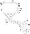
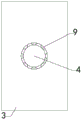
Fig. 1 is a schematic structural diagram of the present invention;
FIG. 2 is an enlarged view of a portion A of FIG. 1;
FIG. 3 is a schematic top view showing the connection between the rotating shaft and the retaining plate;
FIG. 4 is a schematic left side view of the connection of the feeding rod, the driving rod, the fixing rod and the upper ball bearing;
FIG. 5 is a schematic top view of the connection of the placing plate, the feeding rod and the plurality of groups of balls;
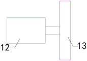
FIG. 6 is a schematic left side view of the connection of the drive motor and the turntable;
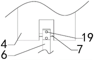
in the drawings, the reference numbers: 1. a storage bin; 2. a slideway; 3. placing the plate; 4. a feeding rod; 5. a base; 6. a drive rod; 7. fixing the rod; 8. a cover plate; 9. a ball bearing; 10. a rotating shaft; 11. an anti-drop plate; 12. a drive motor; 13. a turntable; 14. a platform; 15. a vibration motor; 16. a fixed block; 17. an L-shaped rod; 18. a stop lever; 19. an upper ball bearing; 20. a lower ball bearing; 21. a U-shaped handle; 22. a partition plate; 23. a limiting plate; 24. a transparent plate; 25. a reinforcing rod.
Detailed Description
The following detailed description of the embodiments of the present invention is provided with reference to the accompanying drawings and examples. The following examples are intended to illustrate the invention, but are not intended to limit the scope of the invention.
As shown in figures 1 to 6, the automatic loading and unloading device for the centerless grinding machine comprises a storage bin 1, a slide way 2, a placing plate 3, a loading rod 4, a base 5, a driving rod 6, a fixing rod 7, a cover plate 8, a plurality of groups of balls 9, a rotating shaft 10 and an anti-falling plate 11, wherein a placing cavity is arranged inside the storage bin 1, the top side wall and the bottom side wall of the storage bin 1 are respectively communicated with a placing port and a discharging port, one end of the slide way 2 is connected with the left end of the bottom side wall of the storage bin 1, the other end of the slide way 2 is connected with the left end of the placing plate 3, a limiting hole is arranged on the placing plate 3, the bottom end of the loading rod 4 passes through the limiting hole, an annular groove is arranged on the inner side wall of the limiting hole, most of the plurality of groups of balls 9 are positioned inside the annular groove, the plurality of groups of balls 9 are all tangent to the outer side wall of the, the fixing rod 7 penetrates through the upper rotating hole, the front end and the rear end of the fixing rod 7 are respectively connected with the front side wall and the inner rear side wall in the rotating groove, the top end of the base 5 is provided with a driving motor 12, the output end of the front end of the driving motor 12 is provided with a rotating disc 13, the rear end of the rotating shaft 10 penetrates through the lower rotating hole and then is connected with the top end of the front side wall of the rotating disc 13, the front end of the rotating shaft 10 is connected with the central area of the rear side wall of the anti-falling plate 11, the outer side wall of the storage bin 1 is provided with a platform 14, the platform 14 is provided with a vibrating motor 15, the top end of the outer side wall of the storage bin 1 is provided with a fixing block 16, the top side wall of the fixing block 16 is provided with a hinge groove communicated in; the storage bin, the base, the slide way and the placing plate are fixed by the outside, under the mutual matching of the fixing block and the L-shaped rod, the cover plate can rotate, the cover plate is opened, steel pipes are horizontally placed in the storage bin in parallel, the vibration motor is started at the same time, the vibration motor drives the steel pipes to vibrate, the steel pipes are further made to be horizontally arranged in parallel, under the action of gravity, the steel pipes slide to the placing plate along the slide way, the stop lever limits the steel pipes, the driving motor is electrified to drive the rotary disc to rotate, most areas of the multiple groups of balls are located in the annular groove, so that the feeding rods are limited, under the mutual matching of the driving rod, the fixed rod, the cover plate, the multiple groups of balls, the rotating shaft, the anti-falling plate and the rotary disc, the driving motor rotates to drive the feeding rods to reciprocate up and down, when the top ends of the feeding rods are located at the bottom ends, then the feeding rod rises to lift the height of the group of steel pipes, the side wall of the top of the feeding rod is inclined, the group of steel pipes rotate to the feeding end of the centerless cylindrical grinding machine, the driving motor rotates to enable the discharging rod to move up and down in a reciprocating mode, the steel pipes are fed into the feeding end of the centerless cylindrical grinding machine one by one, the structure is simple, the labor intensity is reduced, and the working efficiency is improved.
The automatic loading and unloading device for the centerless grinding machine has the advantages that the upper ball bearing 19 is arranged at the upper rotating hole, and the fixed rod 7 is in key connection with the upper ball bearing 19; the upper ball bearing improves the stability of the feeding rod during up-and-down reciprocating movement.
The automatic loading and unloading device for the centerless grinding machine has the advantages that the lower ball bearing 20 is arranged at the lower rotating hole, and the rotating shaft 10 is in key connection with the lower ball bearing 20; the lower ball bearing improves the stability of the feeding rod during up-and-down reciprocating movement.
The utility model discloses an automatic loading and unloading device for a centerless grinding machine, a U-shaped handle 21 is arranged on the top side wall of a cover plate 8; the U-shaped handle is grasped to open the cover plate, so that the cover plate is more convenient to bear force, and the use convenience is improved.
The utility model discloses an automatic loading and unloading device for a centerless grinding machine, wherein the front end and the rear end of the top side wall of a slide way 2 are both provided with a clapboard 22; the two groups of partition plates prevent the steel pipe from separating from the slideway.
The utility model discloses an automatic loading and unloading device of a centerless grinding machine, the front end and the rear end of the side wall of the top of a placing plate 3 are both provided with a limiting plate 23; two sets of limiting plates prevent that the steel pipe from breaking away from and placing the board.
The utility model discloses an automatic loading and unloading device for a centerless grinding machine, an observation hole is arranged on a cover plate 8, and a transparent plate 24 is arranged at the observation hole; the number of steel pipes in the bin is observed through the transparent plate.
The automatic loading and unloading device for the centerless grinding machine of the utility model also comprises a reinforcing rod 25, wherein the top end and the bottom end of the reinforcing rod 25 are respectively fixedly connected with the platform 14 and the storage bin 1; form stable triangle-shaped structure between stiffener platform and the feed bin three, improve stability in use.
The utility model discloses an automatic unloader that goes up of centerless grinder, the feed bin, a pedestal, slide and placing plate all need the external world to fix, under the mutually supporting of fixed block and L type pole, the apron is rotatable, grasp U type handle and make the apron open, open the apron, place the steel pipe horizontally side by side inside the feed bin, observe the inside steel pipe quantity of feed bin through the transparent plate, form stable triangle-shaped structure between stiffener platform and the feed bin three, turn on vibrating motor simultaneously, vibrating motor drives the steel pipe and vibrates, further make the steel pipe be horizontal side by side form, under the action of gravity, the steel pipe slides to placing plate along the slide, two sets of baffles prevent that the steel pipe from breaking away from the slide, two sets of limiting plates prevent that the steel pipe breaks away from placing plate, the pin is spacing to the steel pipe, drive the carousel rotation after will driving motor circular telegram, most region of multiunit ball all lies in, thereby carry out spacingly to the feed bar, at last ball bearing, lower ball bearing, the actuating lever, the dead lever, the apron, the multiunit ball, the apparatus further comprises a rotating shaft, under mutually supporting of anticreep board and carousel, driving motor rotates and drives feed bar reciprocating motion from top to bottom, when feed bar top is located the bottommost, the feed bar top is located spacing downthehole portion, a set of steel pipe bottom is located directly over the feed bar this moment, then the feed bar rises to promote this a set of steel pipe height, and feed bar top lateral wall is the slope form, this a set of steel pipe rotates to centerless cylindrical grinder material loading end, thereby driving motor rotates and makes feed bar reciprocating motion from top to bottom, the steel pipe is sent into centerless cylindrical grinder material loading end one by one.
The utility model discloses an automatic unloader that goes up of centerless grinder, above the mounting means of all parts, connected mode or the mode that sets up are the welding, riveting or other common mechanical mode, wherein can slide/rotate fixedly promptly for slide/not dropping under the rotation state, sealed intercommunication is sealed when two connecting pieces communicate promptly, and the concrete structure of its all parts, model and coefficient index are its from the area technique, as long as can reach all implementation of its beneficial effect, above-mentioned all with electric module and with electric common electrical part in market, buy when returning to the use only need connect according to the mutual electricity of the instruction manual that together buy back and can use, and control module is its common from taking the module, the event is no longer repeated here.
The utility model relates to an automatic loading and unloading device of a centerless grinder, under the condition of not explaining the contrary, "upper, lower, left, right, front, back, inner, outer, vertical and horizontal" and other orientation words included in terms only represent the orientation of the terms in the normal use state, or be a trivial term understood by those skilled in the art, and should not be considered as limiting the term, at the same time, the numerical terms "first," "second," and "third," etc. do not denote any particular quantity or order, but rather are used to distinguish one from another, furthermore, the terms "comprises," "comprising," or any other variation thereof, are intended to cover a non-exclusive inclusion, such that a process, method, article, or apparatus that comprises a list of elements does not include only those elements, but also includes other elements not expressly listed or inherent to such process, method, article, or apparatus.
The foregoing is only a preferred embodiment of the present invention, and it should be noted that, for those skilled in the art, a plurality of modifications and variations can be made without departing from the technical principle of the present invention, and these modifications and variations should also be regarded as the protection scope of the present invention.
Claims (8)
1. An automatic loading and unloading device for a centerless grinding machine is characterized by comprising a storage bin (1), a slide way (2), a placing plate (3), a loading rod (4), a base (5), a driving rod (6), a fixing rod (7), a cover plate (8), a plurality of groups of balls (9), a rotating shaft (10) and an anti-falling plate (11), wherein a placing cavity is arranged inside the storage bin (1), the top side wall and the bottom side wall of the storage bin (1) are respectively communicated with a placing opening and a discharging opening, one end of the slide way (2) is connected with the left end of the bottom side wall of the storage bin (1), the other end of the slide way (2) is connected with the left end of the placing plate (3), a limiting hole is arranged on the placing plate (3), the bottom end of the loading rod (4) penetrates through the limiting hole, a ring groove is arranged on the inner side wall of the limiting hole, most regions of the plurality of the groups of balls (9) are all, the bottom side wall of the feeding rod (4) is provided with a rotating groove communicated in the left-right direction, the top end and the bottom end of the driving rod (6) are respectively provided with an upper rotating hole and a lower rotating hole, the fixing rod (7) penetrates through the upper rotating hole, the front end and the rear end of the fixing rod (7) are respectively connected with the front side wall and the inner rear side wall in the rotating groove, the top end of the base (5) is provided with a driving motor (12), the output end of the front end of the driving motor (12) is provided with a rotating disc (13), the rear end of the rotating shaft (10) penetrates through the lower rotating hole and then is connected with the top end of the front side wall of the rotating disc (13), the front end of the rotating shaft (10) is connected with the central area of the rear side wall of the anti-falling plate (11), the outer side wall of the storage bin (1) is provided with a platform (14), the platform (14) is, the right end of the outer side wall of the cover plate (8) is provided with an L-shaped rod (17), the bottom end of the L-shaped rod (17) is inserted into the inner side of the hinge groove and is hinged with the inner side wall of the hinge groove, and the right side wall of the placing plate (3) is provided with a stop lever (18).
2. The automatic loading and unloading device of the centerless grinder of claim 1, wherein the upper ball bearing (19) is arranged at the upper rotating hole, and the fixing rod (7) is in key connection with the upper ball bearing (19).
3. The automatic loading and unloading device for the centerless grinder as claimed in claim 2, wherein a lower ball bearing (20) is arranged at the lower rotating hole, and the rotating shaft (10) is connected with the lower ball bearing (20) in a key mode.
4. The automatic loading and unloading device for the centerless grinder as claimed in claim 3, wherein the top side wall of the cover plate (8) is provided with a U-shaped handle (21).
5. The automatic loading and unloading device for the centerless grinding machine as claimed in claim 4, wherein the front end and the rear end of the top side wall of the slideway (2) are provided with partition plates (22).
6. The automatic loading and unloading device for the centerless grinding machine as claimed in claim 5, characterized in that the front end and the rear end of the top side wall of the placing plate (3) are provided with limiting plates (23).
7. The automatic loading and unloading device for the centerless grinding machine as claimed in claim 6, wherein the cover plate (8) is provided with an observation hole, and a transparent plate (24) is arranged at the observation hole.
8. The automatic loading and unloading device of the centerless grinder of claim 7, further comprising a reinforcing rod (25), wherein the top end and the bottom end of the reinforcing rod (25) are respectively fixedly connected with the platform (14) and the storage bin (1).
Priority Applications (1)
| Application Number | Priority Date | Filing Date | Title |
|---|---|---|---|
| CN201921002343.6U CN210281663U (en) | 2019-06-29 | 2019-06-29 | Automatic loading and unloading device of centerless grinding machine |
Applications Claiming Priority (1)
| Application Number | Priority Date | Filing Date | Title |
|---|---|---|---|
| CN201921002343.6U CN210281663U (en) | 2019-06-29 | 2019-06-29 | Automatic loading and unloading device of centerless grinding machine |
Publications (1)
| Publication Number | Publication Date |
|---|---|
| CN210281663U true CN210281663U (en) | 2020-04-10 |
Family
ID=70099700
Family Applications (1)
| Application Number | Title | Priority Date | Filing Date |
|---|---|---|---|
| CN201921002343.6U Expired - Fee Related CN210281663U (en) | 2019-06-29 | 2019-06-29 | Automatic loading and unloading device of centerless grinding machine |
Country Status (1)
| Country | Link |
|---|---|
| CN (1) | CN210281663U (en) |
Cited By (1)
| Publication number | Priority date | Publication date | Assignee | Title |
|---|---|---|---|---|
| CN115519410A (en) * | 2022-09-23 | 2022-12-27 | 鹰潭泓腾金属制品有限公司 | Copper rod polishing device capable of achieving rapid positioning and processing method thereof |
-
2019
- 2019-06-29 CN CN201921002343.6U patent/CN210281663U/en not_active Expired - Fee Related
Cited By (1)
| Publication number | Priority date | Publication date | Assignee | Title |
|---|---|---|---|---|
| CN115519410A (en) * | 2022-09-23 | 2022-12-27 | 鹰潭泓腾金属制品有限公司 | Copper rod polishing device capable of achieving rapid positioning and processing method thereof |
Similar Documents
| Publication | Publication Date | Title |
|---|---|---|
| CN210281663U (en) | Automatic loading and unloading device of centerless grinding machine | |
| CN107253565A (en) | A carrying device for easy search of auto parts | |
| CN203751869U (en) | Automatic battery plate edge brushing machine | |
| CN205802496U (en) | Sack-filling device | |
| CN218799040U (en) | Foundry goods is with vibration hulling device | |
| CN102370577A (en) | Polishing coating machine with pot head capable of automatically turning | |
| CN107528192B (en) | Carbon brush factory supplies proportioner | |
| CN101596528A (en) | A kind of mobile cylindrical grain cleaner | |
| CN214133818U (en) | A high-speed steel ball cold heading machine automatic feeding device | |
| CN211220209U (en) | Sand throwing device for producing standard parts | |
| CN219130160U (en) | Disc washing device | |
| CN111495476A (en) | Medical intermediate grinding equipment | |
| CN213351937U (en) | Automatic balance mechanism for ground copper parts | |
| CN214266774U (en) | Bar white carbon black briquetting device | |
| CN215612998U (en) | Centrifugal stone removing equipment for processing medlar | |
| CN211076665U (en) | Textile powder dye bag breaking device | |
| CN115535644A (en) | Feeding and discharging device | |
| CN207548372U (en) | A kind of building machinery process equipment | |
| CN223249374U (en) | Graphite material crushing equipment | |
| CN204842589U (en) | Drift equipment of push rod for mould | |
| CN218057612U (en) | Bar-shaped magnetic core forming and feeding device | |
| CN208712232U (en) | Can automatic sorting spring spring forming machine | |
| CN204817635U (en) | Drift processing all -in -one of push rod for mould | |
| KR101831139B1 (en) | motor operated mill | |
| CN104998942A (en) | Punch head processing all-in-one machine of push rod for mould |
Legal Events
| Date | Code | Title | Description |
|---|---|---|---|
| GR01 | Patent grant | ||
| GR01 | Patent grant | ||
| CF01 | Termination of patent right due to non-payment of annual fee |
Granted publication date: 20200410 |
|
| CF01 | Termination of patent right due to non-payment of annual fee |