CN210274158U - Cell-phone backlight glues integrative structure of iron - Google Patents
Cell-phone backlight glues integrative structure of iron Download PDFInfo
- Publication number
- CN210274158U CN210274158U CN201921437118.5U CN201921437118U CN210274158U CN 210274158 U CN210274158 U CN 210274158U CN 201921437118 U CN201921437118 U CN 201921437118U CN 210274158 U CN210274158 U CN 210274158U
- Authority
- CN
- China
- Prior art keywords
- frame
- iron
- rubber
- glue
- chase
- Prior art date
- Legal status (The legal status is an assumption and is not a legal conclusion. Google has not performed a legal analysis and makes no representation as to the accuracy of the status listed.)
- Active
Links
Images

Abstract
The utility model provides a cell-phone backlight glues integrative structure of iron, includes gluey frame and locates glue the chase in the frame, the chase embedding is inside gluey frame body, the chase includes backplate and a plurality of group along the lateral wall that the backplate border set up, be formed with a plurality of admittedly on the lateral wall and glue the hole and bend the portion, glue the frame top surface cover in the chase top surface, it passes through for the colloid to glue the hole admittedly and mould plastics integrated into one piece in the chase. The utility model has simple structure and reasonable design, realizes the integrated design of the rubber frame and the iron frame, can reduce the procedure of assembling the iron frame and the rubber frame in the aspect of assembly of the production line, and can enhance the passing rate of the drop reliability test; meanwhile, in order to meet the development requirement of 5G backlight, the edges, corners or the interior of the iron frame adopt a partial windowing structure, so that the influence of the metal frame on signals and antennas can be avoided.
Description
Technical Field
The utility model relates to a relevant technical field of cell-phone backlight, concretely relates to cell-phone backlight glues integrative structure of iron.
Background
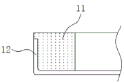
Liquid Crystal Displays (LCDs) are widely used in the field of display technology, and generally, an electric field formed by two pieces of conductive glass drives a liquid crystal located between the pieces of conductive glass to realize a display function, but the liquid crystal itself cannot emit light, so that the display function needs to be really realized by an external light source, and currently, the mainstream backlight sources include an LED backlight source and a TTF backlight source. The general LCD includes the plastic material's of backlight main part frame of gluing, install various parts such as reflector plate, light guide plate, TAPE spare, FPC, LED in gluing the frame, combine as shown in figure 1, the integrative structure of gluey frame and chase plastic is wrapped by chase 12 by plastic 11 in prior art, then adopt right angle screens fixed, this kind of structure is with high costs, and the fastness is relatively poor, when falling, chase 12 breaks away from with gluey frame 11 easily, present signal network is developing toward 5G, and 5G has more special requirements to structures such as internal antenna, metalwork. Therefore, there is a need to optimize existing backlight structures.
SUMMERY OF THE UTILITY MODEL
The utility model aims at providing a cell-phone backlight glues integrative structure of iron has overcome not enough among the prior art, provides a cell-phone backlight glues integrative structure of iron.
The utility model provides a cell-phone backlight glues integrative structure of iron, includes gluey frame and locates glue the iron frame in the frame, its characterized in that: the iron frame is embedded in the rubber frame body, the iron frame comprises a backboard and a plurality of groups of side walls arranged along the edge of the backboard, a plurality of glue fixing holes and a bending part are formed in the side walls, the top surface of the rubber frame covers the top surface of the iron frame, and the rubber frame is an adhesive body and is formed in the iron frame through the glue fixing holes in an injection molding mode.
Furthermore, the bending part is distributed on at least one side wall of the iron frame at a certain interval.
Furthermore, the bending part is integrally distributed on at least one side wall of the iron frame.
Furthermore, the included angle formed between the bending part and the side wall is 45-90 degrees.
Furthermore, a plurality of windowing structures are arranged in the iron frame back plate.
The utility model discloses beneficial effect who has: compared with the prior art, the utility model realizes the integrated design of the rubber frame and the iron frame, can reduce the procedure of assembling the iron frame and the rubber frame in the aspect of assembly of the production line, and can enhance the passing rate of the drop reliability test; meanwhile, in order to meet the development requirement of 5G backlight, the edges, corners or the interior of the iron frame adopt a partial windowing structure, so that the influence of the metal frame on signals and antennas can be avoided.
Drawings
Fig. 1 is a schematic view of an integrated structure of a conventional backlight rubber.
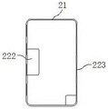
Fig. 2 is a schematic view of the integrated structure of the backlight rubber and iron of the present invention.
Fig. 3 is a side view of the glue-fixing hole of the integrated backlight glue-iron structure of the present invention.
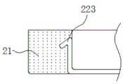
Fig. 4 is a side view of the bending portion of the integrated backlight rubber-iron structure of the present invention.
Detailed Description
In order to make the objects, technical solutions and advantages of the embodiments of the present invention clearer, the embodiments of the present invention will be clearly and completely described below with reference to the accompanying drawings in the embodiments of the present invention, and it is obvious that the described embodiments are some, but not all, embodiments of the present invention. Based on the embodiments in the present invention, all other embodiments obtained by a person skilled in the art without creative work belong to the protection scope of the present invention.
Example 1
As shown in fig. 2, fig. 3 and fig. 4, a mobile phone backlight rubber-iron integrated structure includes a rubber frame 21 and an iron frame 22 disposed in the rubber frame 21, the iron frame 22 is embedded inside a rubber frame 21 body, the iron frame 22 includes a backboard and a plurality of groups along a side wall of the backboard edge, a plurality of rubber fixing holes 221 and a bending portion 223 are formed on the side wall, the rubber fixing holes 221 are located on the surface of the side wall, the rubber frame 21 is formed by injecting a rubber through the rubber fixing holes 221 in the iron frame 22, it should be noted that the rubber frame 21 is formed by injecting a rubber through the rubber fixing holes 221 in the iron frame 22, and the rubber fixing holes 221 can also be located at corner positions of the backboard and the side wall.
In this embodiment, the bending portions 223 are distributed on at least one side wall of the iron frame 22 at a certain interval. The side walls of the iron frame 221 in this embodiment are all provided with bending portions 223, wherein an included angle formed between the bending portions 223 and the side walls is 45-90 degrees, and the bending portions 223 and the side walls form a barb-shaped fit, so that the rubber frame 21 and the iron frame 22 can be conveniently fixed.
In this embodiment, the bending portions 223 are integrally distributed on at least one side wall of the iron frame 22, and the side walls of the iron frame 221 in this embodiment are all provided with the bending portions 223, wherein an included angle formed between the bending portions 223 and the side walls is 45-90 degrees, and the bending portions 223 and the side walls form barb-shaped matching.
In this embodiment, the back plate of the bezel 22 adopts the partially windowed structure 222, so that the influence of the metal frame on the signal and the antenna can be avoided, and the position and the size are determined by the specific structure.
In this embodiment, the glue fixing hole 221 and the bending portion 223 for preventing the glue and iron separation may be used separately or simultaneously, the glue frame 21 may completely cover the iron frame 22 retaining wall in the middle, and the glue fixing hole 221 is matched to prevent the glue and iron separation.
The above embodiments are only used to illustrate the present invention and not to limit the technical solutions of the present invention, therefore, although the present invention has been described in detail with reference to the above embodiments, it should be understood by those skilled in the art that the present invention can be modified or replaced by other means without departing from the spirit and scope of the present invention, and all modifications thereof should be covered by the scope of the claims of the present invention.
Claims (5)
1. The utility model provides a cell-phone backlight glues integrative structure of iron, includes gluey frame and locates glue the iron frame in the frame, its characterized in that: the iron frame is embedded in the rubber frame body, the iron frame comprises a backboard and a plurality of groups of side walls arranged along the edge of the backboard, a plurality of glue fixing holes and a bending part are formed in the side walls, the top surface of the rubber frame covers the top surface of the iron frame, and the rubber frame is an adhesive body and is formed in the iron frame through the glue fixing holes in an injection molding mode.
2. The integrated structure of backlight source rubber and iron of the mobile phone according to claim 1, characterized in that: the bending part is distributed on at least one side wall of the iron frame at a certain interval.
3. The integrated structure of backlight source rubber and iron of the mobile phone according to claim 1, characterized in that: the bending part is integrally distributed on at least one side wall of the iron frame.
4. The integrated structure of backlight source rubber and iron of the mobile phone according to claim 1, characterized in that: the included angle formed between the bending part and the side wall is 45-90 degrees.
5. The integrated structure of the backlight source rubber and iron of the mobile phone according to claim 1, characterized in that: a plurality of windowing structures are arranged in the iron frame back plate.
Priority Applications (1)
| Application Number | Priority Date | Filing Date | Title |
|---|---|---|---|
| CN201921437118.5U CN210274158U (en) | 2019-09-02 | 2019-09-02 | Cell-phone backlight glues integrative structure of iron |
Applications Claiming Priority (1)
| Application Number | Priority Date | Filing Date | Title |
|---|---|---|---|
| CN201921437118.5U CN210274158U (en) | 2019-09-02 | 2019-09-02 | Cell-phone backlight glues integrative structure of iron |
Publications (1)
| Publication Number | Publication Date |
|---|---|
| CN210274158U true CN210274158U (en) | 2020-04-07 |
Family
ID=70018527
Family Applications (1)
| Application Number | Title | Priority Date | Filing Date |
|---|---|---|---|
| CN201921437118.5U Active CN210274158U (en) | 2019-09-02 | 2019-09-02 | Cell-phone backlight glues integrative structure of iron |
Country Status (1)
| Country | Link |
|---|---|
| CN (1) | CN210274158U (en) |
-
2019
- 2019-09-02 CN CN201921437118.5U patent/CN210274158U/en active Active
Similar Documents
| Publication | Publication Date | Title |
|---|---|---|
| US10989860B2 (en) | Backlight module and display device | |
| CN205210477U (en) | Novel narrow frame back of body light structures and liquid crystal display device | |
| CN107728379B (en) | Ultrathin direct type backlight flat-panel liquid crystal display module | |
| US7920222B2 (en) | LCD and backlight module, front frame, and back bezel thereof | |
| CN106444121B (en) | Display device | |
| TWI541695B (en) | Curved touch device | |
| CN103810942A (en) | Curved display apparatus | |
| CN109765716B (en) | Ultra-narrow frame liquid crystal display module | |
| CN202453599U (en) | Liquid crystal module structure with film positioning function | |
| CN111552116B (en) | Liquid crystal module and liquid crystal display device | |
| CN104806932A (en) | Backlight module and display device | |
| US10908448B1 (en) | Display apparatus | |
| US20200218308A1 (en) | Backlight Module and Display Device | |
| CN101655636A (en) | Side-view backlight module, liquid crystal display device and method for assembling side-view backlight module and liquid crystal display device | |
| CN110908191A (en) | Display module and display device | |
| CN210274158U (en) | Cell-phone backlight glues integrative structure of iron | |
| CN204964951U (en) | Backlight subassembly, display device | |
| WO2019085762A1 (en) | Backlight module and display device | |
| CN202915279U (en) | Lower brightness enhancement film, backlight module and liquid-crystal display device | |
| CN204853358U (en) | Limit structure , backlight unit and display device | |
| CN210401954U (en) | Back plate and narrow-frame backlight module | |
| US10605973B2 (en) | Light guide plate and display device | |
| CN215729188U (en) | Backlight module, liquid crystal display device and electronic equipment | |
| CN219718305U (en) | Novel backlight source for improving four R angle deformation of mobile phone mechanical experiment backlight | |
| CN219285547U (en) | Liquid crystal display module |
Legal Events
| Date | Code | Title | Description |
|---|---|---|---|
| GR01 | Patent grant | ||
| GR01 | Patent grant | ||
| TR01 | Transfer of patent right | ||
| TR01 | Transfer of patent right |
Effective date of registration: 20200612 Address after: 243000 five Jinshan Road 1188, Ma'anshan economic and Technological Development Zone, Anhui province 207 Patentee after: MAANSHAN DACANG PRECISION TECHNOLOGY Co.,Ltd. Address before: 518000. E building, Shiyan Industrial Street, Fukang mountain area, Shiyan City, Shenzhen, Guangdong, Baoan District Patentee before: SHENZHEN TECHASER TECHNOLOGIES Co.,Ltd. |