CN210257087U - Injection mold convenient to take off material - Google Patents
Injection mold convenient to take off material Download PDFInfo
- Publication number
- CN210257087U CN210257087U CN201920858603.3U CN201920858603U CN210257087U CN 210257087 U CN210257087 U CN 210257087U CN 201920858603 U CN201920858603 U CN 201920858603U CN 210257087 U CN210257087 U CN 210257087U
- Authority
- CN
- China
- Prior art keywords
- wall
- top outer
- hydraulic
- plate
- injection mold
- Prior art date
- Legal status (The legal status is an assumption and is not a legal conclusion. Google has not performed a legal analysis and makes no representation as to the accuracy of the status listed.)
- Active
Links
Images

Abstract
The utility model discloses an injection mold convenient to take off material, comprising a base plate, the top outer wall four corners of bottom plate all is equipped with the bracing piece, and the top outer wall of four bracing pieces is equipped with same roof, the top outer wall of bottom plate is equipped with three support column, and the top outer wall of three support column is equipped with same cover half, the bottom outer wall of cover half is opened there is the through-hole, and the bottom plate is located the top outer wall of through-hole below and is equipped with No. two hydraulic stems, and the top outer wall of No. two hydraulic stems is equipped with the liftout plate, and the external diameter of liftout plate is the same with the internal diameter of through-hole, the top outer wall of roof is equipped with the pneumatic cylinder, and the bottom outer wall. The utility model discloses a be provided with No. two hydraulic stems and liftout plate, after injection moulding, treat the model cooling back, adjust No. two hydraulic stems for the liftout plate is ejecting with the shaping article, is convenient for collect it, and convenient and fast, and then improves work efficiency.
Description
Technical Field
The utility model relates to an injection mold technical field especially relates to an injection mold convenient to take off material.
Background
The injection mold is a tool for producing plastic products and also a tool for endowing the plastic products with complete structures and accurate dimensions, and the injection molding is a processing method used for batch production of parts with complex shapes, in particular to a method for injecting heated and melted plastics into a mold cavity from an injection molding machine at high pressure and obtaining a formed product after cooling and solidification.
Through retrieval, chinese patent application No. CN201820002605.8 discloses an injection mold with a water blowing device, which comprises an injection mold, a base, an upper support plate and a lower support plate. The injection mold in the above patent has the following disadvantages: after the injection mold in the comparison file is used, a formed product is not easy to take out, the working efficiency is reduced, and the working progress is influenced.
SUMMERY OF THE UTILITY MODEL
The utility model aims at solving the defects existing in the prior art and providing an injection mold convenient for stripping materials.
In order to achieve the above purpose, the utility model adopts the following technical scheme:
the utility model provides an injection mold convenient to take off material, includes the bottom plate, the top outer wall four corners of bottom plate all is equipped with the bracing piece, and the top outer wall of four bracing pieces is equipped with same roof, the top outer wall of bottom plate is equipped with three support column, and the top outer wall of three support column is equipped with same cover half, the bottom outer wall of cover half is opened there is the through-hole, and the bottom plate is located the top outer wall of through-hole below and is equipped with No. two hydraulic stems, and the top outer wall of No. two hydraulic stems is equipped with the liftout plate, and the external diameter of liftout.
Furthermore, the top outer wall of the top plate is provided with a hydraulic cylinder, and the bottom outer wall of the hydraulic cylinder is provided with a movable mold.
Furthermore, the top outer wall both ends of movable mould all are equipped with the inlet pipe.
Furthermore, the outer walls of the tops, located on the two sides of the movable die, of the bottom plate are provided with two third hydraulic rods, and the four third hydraulic rods are connected with a synchronous hydraulic system.
Furthermore, every two the top outer wall of No. three hydraulic stems all is equipped with same limiting plate, and the relative one side outer wall of two limiting plates all is equipped with two hydraulic stems, and the other end of a hydraulic stem is equipped with the spacing ring, and four hydraulic stems are connected with synchronous hydraulic system.
Further, the outer wall of the fixed die is provided with a cooling cavity, and the outer wall of the cooling cavity is provided with a liquid inlet pipe.
The utility model has the advantages that:
1. through the arrangement of the second hydraulic rod and the ejector plate, after injection molding and cooling of the model, the second hydraulic rod is adjusted, so that the ejector plate ejects a molded product, the molded product is convenient to collect, and the ejection device is convenient and quick, and further improves the working efficiency;
2. by arranging the third hydraulic rod, the limiting plate, the first hydraulic rod and the limiting ring, when a formed product is taken out, the limiting ring is fixed by adjusting the first hydraulic rod, and then the third hydraulic rod is adjusted to take the formed product out, so that the stripping efficiency is further improved;
3. through being provided with cooling chamber and feed liquor pipe, the feed liquor union coupling has the coolant liquid bin, and the back is accomplished in moulding plastics, adds the coolant liquid in to the cooling chamber, and the shaping speed of mould improves work efficiency with higher speed.
Drawings
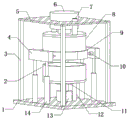
FIG. 1 is a schematic structural diagram of an injection mold facilitating stripping as set forth in example 1;
FIG. 2 is a structural side view of an injection mold facilitating stripping as set forth in example 1;
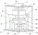
fig. 3 is a schematic structural diagram of an injection mold facilitating stripping in embodiment 2.
In the figure: 1-bottom plate, 2-fixed die, 3-supporting rod, 4-limiting plate, 5-top plate, 6-hydraulic cylinder, 7-feeding pipe, 8-movable die, 9-limiting ring, 10-first hydraulic rod, 11-ejector plate, 12-supporting column, 13-second hydraulic rod, 14-third hydraulic rod, 15-cooling cavity and 16-liquid inlet pipe.
Detailed Description
The technical solution of the present patent will be described in further detail with reference to the following embodiments.
Reference will now be made in detail to embodiments of the present patent, examples of which are illustrated in the accompanying drawings, wherein like or similar reference numerals refer to the same or similar elements or elements having the same or similar function throughout. The embodiments described below with reference to the drawings are exemplary only for the purpose of explaining the present patent and are not to be construed as limiting the present patent.
In the description of this patent, it is to be understood that the terms "center," "upper," "lower," "front," "rear," "left," "right," "vertical," "horizontal," "top," "bottom," "inner," "outer," and the like are used in the orientations and positional relationships indicated in the drawings for the convenience of describing the patent and for the simplicity of description, and are not intended to indicate or imply that the referenced devices or elements must have a particular orientation, be constructed and operated in a particular orientation, and are not to be considered limiting of the patent.
In the description of this patent, it is noted that unless otherwise specifically stated or limited, the terms "mounted," "connected," and "disposed" are to be construed broadly and can include, for example, fixedly connected, disposed, detachably connected, disposed, or integrally connected and disposed. The specific meaning of the above terms in this patent may be understood by those of ordinary skill in the art as appropriate.
Example 1
Referring to fig. 1-2, an injection mold convenient for stripping comprises a bottom plate 1, supporting rods 3 fixed at four corners of the outer wall of the top of the bottom plate 1 through screws, the top outer walls of the four support rods 3 are fixed with the same top plate 5 through screws, the top outer wall of the bottom plate 1 is fixed with three support columns 12 through screws, and the outer walls of the tops of the three support columns 12 are fixed with the same fixed mold 2 through screws, the outer wall of the bottom of the fixed mold 2 is provided with a through hole, and the top outer wall of the bottom plate 1 below the through hole is fixed with a second hydraulic rod 13 through screws, the top outer wall of the second hydraulic rod 13 is fixed with an ejector plate 11 through screws, the outer diameter of the ejector plate 11 is the same as the inner diameter of the through hole, after injection molding, after the mold is cooled, the second hydraulic rod 13 is adjusted, make ejector plate 11 ejecting with the shaping article, be convenient for collect it, convenient and fast, and then improve work efficiency.
Wherein, the top outer wall of roof 5 has pneumatic cylinder 6 through the fix with screw, and the bottom outer wall of pneumatic cylinder 6 has movable mould 8 through the fix with screw.
Wherein, the top outer wall both ends of movable mould 8 all have inlet pipe 7 through flange joint.
Wherein, the bottom plate 1 is located the top outer wall of movable mould 8 both sides and all is fixed with two No. three hydraulic stems 14 through the screw, and four No. three hydraulic stems 14 are connected with synchronous hydraulic system.
Wherein, the top outer wall of per two No. three hydraulic stems 14 all has same limiting plate 4 through the fix with screw, and the relative one side outer wall of two limiting plates 4 all has two hydraulic stems 10 through the fix with screw, the other end of a hydraulic stem 10 passes through fix with screw spacing ring 9, four hydraulic stems 10 are connected with synchronous hydraulic system, when carrying out taking out of shaping article, make spacing ring 9 fixed with it through adjusting a hydraulic stem 10, adjust No. three hydraulic stems 14 and take it out then, further improve the efficiency of taking off the material.
The working principle is as follows: during the use, adjust hydraulic cylinder 6 and make movable mould 8 and cover half 2 contact, then carry out the interpolation of material through inlet pipe 7, after moulding plastics, treat the shaping back, start hydraulic cylinder 6 once more and make movable mould 8 and cover half 2 part, adjust a hydraulic stem 10 and make two spacing rings 9 spacing fixed to the shaping article, then adjust No. two hydraulic stems 13 and No. three hydraulic stems 14 simultaneously, thereby take out the shaping article from cover half 2, collect it, accomplish the operation.
Example 2
Referring to fig. 3, compared with embodiment 1, the outer wall of the fixed mold 2 is provided with the cooling cavity 15, the outer wall of the cooling cavity 15 is connected with the liquid inlet pipe 16 through the flange, and after the injection molding is completed, the cooling liquid is added into the cooling cavity 15, so that the molding speed of the mold is increased, and the working efficiency is improved.
The working principle is as follows: during the use, adjust hydraulic cylinder 6 and make movable mould 8 and cover half 2 contact, then carry out the interpolation of material through inlet pipe 7, after moulding plastics, to adding the coolant liquid in cooling chamber 15, its cooling process accelerates, treat the shaping back, restart hydraulic cylinder 6 makes movable mould 8 and cover half 2 part again, adjust a hydraulic stem 10 and make two spacing rings 9 spacing fixed to the shaping article, then adjust No. two hydraulic stems 13 and No. three hydraulic stems 14 simultaneously, thereby take out the shaping article from cover half 2, collect it, the operation is accomplished.
The above, only be the concrete implementation of the preferred embodiment of the present invention, but the protection scope of the present invention is not limited thereto, and any person skilled in the art is in the technical scope of the present invention, according to the technical solution of the present invention and the utility model, the concept of which is equivalent to replace or change, should be covered within the protection scope of the present invention.
Claims (6)
1. The utility model provides an injection mold convenient to take off material, includes bottom plate (1), its characterized in that, the top outer wall four corners of bottom plate (1) all is equipped with bracing piece (3), and the top outer wall of four bracing pieces (3) is equipped with same roof (5), the top outer wall of bottom plate (1) is equipped with three support column (12), and the top outer wall of three support column (12) is equipped with same cover half (2), the bottom outer wall of cover half (2) is opened there is the through-hole, and the top outer wall that bottom plate (1) is located the through-hole below is equipped with No. two hydraulic stem (13), and the top outer wall of No. two hydraulic stem (13) is equipped with liftout plate (11), and the external diameter of liftout plate (11) is the.
2. An injection mold facilitating stripping as claimed in claim 1, characterized in that the top outer wall of the top plate (5) is provided with a hydraulic cylinder (6), and the bottom outer wall of the hydraulic cylinder (6) is provided with a movable mold (8).
3. An injection mold facilitating stripping as claimed in claim 2, wherein the top outer wall of the movable mold (8) is provided with a feeding pipe (7) at both ends.
4. An injection mold convenient for stripping as claimed in claim 1, wherein the top outer walls of the bottom plate (1) on both sides of the movable mold (8) are provided with two third hydraulic rods (14), and the four third hydraulic rods (14) are connected with a synchronous hydraulic system.
5. The injection mold convenient to take off material according to claim 4, characterized in that the same limiting plate (4) is arranged on the outer wall of the top of every two hydraulic rods (14) of the third number, two hydraulic rods (10) are arranged on the outer wall of the opposite side of the two limiting plates (4), a limiting ring (9) is arranged at the other end of each hydraulic rod (10), and four hydraulic rods (10) are connected with a synchronous hydraulic system.
6. An injection mould facilitating stripping as claimed in any one of claims 1 to 5, characterised in that the outer wall of the stationary mould (2) is provided with a cooling chamber (15) and the outer wall of the cooling chamber (15) is provided with an inlet pipe (16).
Priority Applications (1)
| Application Number | Priority Date | Filing Date | Title |
|---|---|---|---|
| CN201920858603.3U CN210257087U (en) | 2019-06-10 | 2019-06-10 | Injection mold convenient to take off material |
Applications Claiming Priority (1)
| Application Number | Priority Date | Filing Date | Title |
|---|---|---|---|
| CN201920858603.3U CN210257087U (en) | 2019-06-10 | 2019-06-10 | Injection mold convenient to take off material |
Publications (1)
| Publication Number | Publication Date |
|---|---|
| CN210257087U true CN210257087U (en) | 2020-04-07 |
Family
ID=70041307
Family Applications (1)
| Application Number | Title | Priority Date | Filing Date |
|---|---|---|---|
| CN201920858603.3U Active CN210257087U (en) | 2019-06-10 | 2019-06-10 | Injection mold convenient to take off material |
Country Status (1)
| Country | Link |
|---|---|
| CN (1) | CN210257087U (en) |
Cited By (1)
| Publication number | Priority date | Publication date | Assignee | Title |
|---|---|---|---|---|
| CN113478609A (en) * | 2021-05-31 | 2021-10-08 | 中国十七冶集团有限公司 | Concrete cushion block manufacturing device for controlling plate thickness and using method |
-
2019
- 2019-06-10 CN CN201920858603.3U patent/CN210257087U/en active Active
Cited By (1)
| Publication number | Priority date | Publication date | Assignee | Title |
|---|---|---|---|---|
| CN113478609A (en) * | 2021-05-31 | 2021-10-08 | 中国十七冶集团有限公司 | Concrete cushion block manufacturing device for controlling plate thickness and using method |
Similar Documents
| Publication | Publication Date | Title |
|---|---|---|
| CN210590371U (en) | Quick refrigerated integral type lamp body shell injection moulding mould | |
| CN211518413U (en) | Lawn plastic brick injection mold that cooling effect is good | |
| CN110815739A (en) | Quick cooling mold for plastic processing | |
| CN210257087U (en) | Injection mold convenient to take off material | |
| CN212219104U (en) | Thin wall injection molding quick forming die | |
| CN210880736U (en) | High-efficient injection mold | |
| CN213593513U (en) | Temperature controller shell injection mold | |
| CN213082237U (en) | Quick shedder of foundry goods for injection mold | |
| CN211683268U (en) | Plastic product mold capable of achieving rapid mold opening | |
| CN210308772U (en) | Injection mold with cooling function | |
| CN112757562A (en) | Injection mold convenient for mold installation | |
| CN208730212U (en) | A kind of injection mould is convenient for die-sinking device | |
| CN220826251U (en) | Injection mold forming device | |
| CN219522960U (en) | Aerospace spare part precision die | |
| CN214820573U (en) | Multi-cavity injection mold for correction belt core ring | |
| CN219726972U (en) | Novel parting surface structure of injection mold | |
| CN213617958U (en) | Anti-sticking's rubber coating hardware injection mold | |
| CN213166596U (en) | Kettle body injection mold | |
| CN216182343U (en) | Novel tray forming die | |
| CN210477688U (en) | Injection mold convenient to take off material | |
| CN216683121U (en) | A mould for producing plastic toy | |
| CN216566471U (en) | Pump body mould of centrifugal pump | |
| CN214725768U (en) | Processing die with waste material cutting structure for precision rubber and plastic processing | |
| CN216708217U (en) | Milk tea cup injection mold | |
| CN220362941U (en) | Plastic handle forming die |
Legal Events
| Date | Code | Title | Description |
|---|---|---|---|
| GR01 | Patent grant | ||
| GR01 | Patent grant |