CN210253958U - Automatic line waste material mechanism of punch press - Google Patents
Automatic line waste material mechanism of punch press Download PDFInfo
- Publication number
- CN210253958U CN210253958U CN201920615731.5U CN201920615731U CN210253958U CN 210253958 U CN210253958 U CN 210253958U CN 201920615731 U CN201920615731 U CN 201920615731U CN 210253958 U CN210253958 U CN 210253958U
- Authority
- CN
- China
- Prior art keywords
- waste material
- blanking
- base
- waste
- slide
- Prior art date
- Legal status (The legal status is an assumption and is not a legal conclusion. Google has not performed a legal analysis and makes no representation as to the accuracy of the status listed.)
- Active
Links
Images



Landscapes
- Processing Of Solid Wastes (AREA)
Abstract
The utility model provides an automatic line waste material discharging mechanism of punch press in the technical field of waste material discharging, which comprises a base, be equipped with the bed die on the base, be equipped with a plurality of blanking chamber that is used for connecing the waste material on the bed die, open the upper end of bed die has a plurality of blanking hole, the waste material that falls from the blanking hole gets into corresponding blanking intracavity, be equipped with in the blanking intracavity can be in left and right directions reciprocating motion and the downward shake flitch of slope, shake the flitch and stretch out outside the blanking chamber, fixedly connected with slide board that inclines down on the base, the slide board is in the below of shaking the flitch, the waste material that shakes down from shaking the flitch falls on the slide board, the below of slide board is equipped with the vibration board that can swing in left and right directions, the waste material that shakes down from the slide board falls on the vibration board, the below of vibration board is equipped with the waste material line, the waste material that shakes down; the utility model discloses it is big to tremble the material area, trembles that the material is effectual.
Description
Technical Field
The utility model belongs to the technical field of the waste discharge material, in particular to waste discharge material mechanism.
Background
With the rapid development and the large demand of household appliances, the trend of adopting whole-line automation is a trend, but how to discharge waste materials in the automatic production becomes a bottleneck restricting the high-efficiency production, and particularly for the plate materials generating more waste materials, the difficulty of discharging the waste materials from a machine tool is higher, the time is longer, and more manpower is needed. The utility model discloses the row's of research waste material mechanism can high-efficiently, quick, independently solve the difficult problem that the waste material was arranged to the press, and this kind of waste material structure of arranging is internal originating.
At present, domestic main shake row's waste material mode needs the manpower to release the waste material from the mould, and the waste material can the adhesion on trembling the flitch, trembles the material effect not good, and directly passes through the utility model discloses the device row's waste material, efficiency is higher, and is fast, and the human cost is lower.
In the chinese patent database, the patent name is disclosed as "automatic waste material device of arranging", application publication date is 20150610, application publication number is chinese patent of CN204381438U, the device, including the base, still including locating actuating mechanism on the base and shaking the material mechanism, actuating mechanism includes drive arrangement and telescopic link, telescopic link with shake material mechanism connection, drive arrangement drive telescopic link seesaw to the drive shakes the material mechanism up-and-down motion and shakes the waste material out, it is little to shake the material area, shakes and expects the effect poor.
SUMMERY OF THE UTILITY MODEL
To the defect among the prior art, the utility model discloses an aim at solves the weak point among the prior art, has solved and has shaken among the prior art and expect that the area is little, shakes the poor technical problem of material effect, provides an automatic line row waste material mechanism of punch press, and this device shakes and expects that the area is big, shakes and expects effectually.
The purpose of the utility model is realized like this: the utility model provides an automatic line of punch press arranges waste material mechanism, includes the base, be equipped with the bed die on the base, be equipped with the blanking chamber that a plurality of is used for connecing the waste material on the bed die, open the upper end of bed die has a plurality of blanking hole, and the waste material that falls from the blanking hole gets into the blanking intracavity that corresponds, the blanking intracavity is equipped with can about direction reciprocating motion and the decurrent flitch that trembles of slope, it stretches out outside the blanking chamber to tremble the flitch, fixedly connected with inclines decurrent slide on the base, the slide is in the below of trembleing the flitch, falls on the slide from the waste material that trembles the flitch, and the below of slide is equipped with the waste material line, and the waste material that the board was vibrated down falls into in the waste material line.
In the utility model, the punched waste material falls into the material shaking plate corresponding to the blanking cavity from the blanking hole of the lower die, the material shaking plate moves back and forth in the left and right directions, the waste material on the material shaking plate is shaken onto the sliding plate, the waste material slides onto the shaking plate from the sliding plate, and the shaking plate swings in the left and right directions along the sliding rail, so that the waste material on the shaking plate is shaken onto a waste material line; the utility model discloses a waste material falls into the blanking intracavity of small size earlier, and the waste material that falls into the blanking intracavity falls on the shake flitch of small size, concentrate from each shake flitch again and shake on the slide of large tracts of land, the slide slides the waste material to the shake board of bigger areas, when a plurality of waste material slided to shake the board together, the waste material below is pushed to the gliding by the waste material above, shake the board and shake the limit and shake, the waste material on the oscillation board can not block on shaking the board, make the waste material export from shaking the board more smoothly, fall into the waste line; can be applied to the waste discharge work of waste materials.
In order to realize oscillating the board swing, still be equipped with at least one between waste material line and the base and vibrate the mechanism, vibrate the mechanism including fixing at subaerial mount pad, be equipped with the shock motor on the mount pad, be connected with the rotor arm on the output shaft of shock motor, the one end that the rotor arm stretches out outwards articulates there is the rocking arm, fixedly connected with bracing piece is gone back on the upper portion of mount pad, and the one end that the bracing piece stretches out outwards rotationally is connected with and vibrates the arm, vibrate arm one end down and rocking arm articulated, vibrate the board and vibrate arm one end up articulated.
In order to enhance the oscillation effect of the oscillation plate, an oscillator is arranged on the lower side of the oscillation plate.
For stable structure, the downside of base articulates there are two at least decurrent slide rails of slope, shakes the downside fixedly connected with fixed plate of board, and the rotatable ball of a plurality of is arranged on the fixed plate, and the ball can roll along the slide rail.
In order to realize the reciprocating movement of the material shaking plate in the left-right direction, a linear driver is fixedly connected to the base, a push-pull rod capable of performing reciprocating linear movement in the left-right direction is arranged on the linear driver, a push plate is connected to one end, extending outwards, of the push-pull rod, and one end, extending out of the material dropping cavity, of the material shaking plate is fixedly connected to the push plate.
Drawings
Fig. 1 is a first perspective view of the present invention.
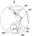
Fig. 2 is a partial enlarged view of a portion a in fig. 1 according to the present invention.
Fig. 3 is a partial enlarged view of the position B in fig. 1 according to the present invention.
Fig. 4 is a second perspective view of the present invention.
Fig. 5 is a partial enlarged view of the point C in fig. 4 according to the present invention.
Fig. 6 is a three-dimensional structure diagram of the present invention.
Fig. 7 is a partial enlarged view of the position D in fig. 6 according to the present invention.
The automatic blanking device comprises a base 1, a lower die 2, a blanking cavity 201, a blanking hole 202, a material shaking plate 3, a material blocking cloth 301, a sliding plate 4, an oscillation plate 5, an oscillation mechanism 6, a mounting seat 601, an oscillation motor 602, an output shaft 602a, a rotating arm 603, a rocker arm 604, an oscillation arm 605, an oscillator 7, a sliding rail 8, a fixing plate 9, a ball 10, a linear actuator 11, a push-pull rod 12, a push plate 13 and a waste material line 14.
Detailed Description
The present invention will be further described with reference to the accompanying drawings.
As shown in fig. 1 to 7, an automatic line waste discharging mechanism for a punch press comprises a base 1, a lower die 2 is arranged on the base 1, a plurality of blanking cavities 201 for receiving waste are arranged on the lower die 2, a plurality of blanking holes 202 are formed in the upper end of the lower die 2, waste falling from the blanking holes 202 enters the corresponding blanking cavities 201, shaking plates 3 capable of reciprocating in the left-right direction and inclining downwards are arranged in the blanking cavities 201, material blocking cloth 301 arranged upwards is arranged on two sides of the shaking plates 3, a linear driver 11 is fixedly connected to the base 1, a push-pull rod 12 capable of reciprocating in the left-right direction is arranged on the linear driver 11, a push plate 13 is connected to one end of the push-pull rod 12 extending outwards, one end of the shaking plate 3 extending out of the blanking cavities 201 is fixedly connected to the push plate 13, the shaking plate 3 extends out of the blanking cavities 201, a sliding plate 4 inclining downwards is fixedly connected to the base 1, the sliding plate 4 is arranged below the material shaking plate 3, waste shaken from the material shaking plate 3 falls on the sliding plate 4, the vibrating plate 5 capable of swinging in the left-right direction is arranged below the sliding plate 4, the oscillator 7 is further arranged below the vibrating plate 5, waste slipped from the sliding plate 4 falls on the vibrating plate 5, a waste line 14 is arranged below the vibrating plate 5, and waste shaken from the vibrating plate 5 falls in the waste line 14; at least one oscillating mechanism 6 is further arranged between the waste line 14 and the base 1, the oscillating mechanism 6 comprises a mounting seat 601 fixed on the ground, an oscillating motor 602 is arranged on the mounting seat 601, a rotating arm 603 is connected to an output shaft 602a of the oscillating motor 602, a rocker arm 604 is hinged to one end of the rotating arm 603 extending outwards, a support rod is further fixedly connected to the upper portion of the mounting seat 601, one end of the support rod extending outwards is rotatably connected with an oscillating arm 605, the downward end of the oscillating arm 605 is hinged to the rocker arm 604, the oscillating plate 5 is hinged to the upward end of the oscillating arm 605, at least two slide rails 8 inclining downwards are hinged to the lower side of the base 1, a fixing plate 9 is fixedly connected to the lower side of the oscillating plate 5, a plurality of rotatable balls 10 are distributed on the fixing plate 9, and; the utility model provides an oscillator 7 is pneumatic oscillator 7.
In the utility model, the waste material is generated by the punch press stamping die (the punch press is a conventional technology, and how the punch press stamping die generates waste material is not repeated in this document), the stamped waste material falls into a plurality of material shaking plates 3 in the blanking cavity 201 from the blanking hole 202 of the lower die 2, the material blocking cloth 301 can prevent the waste material from falling off the material shaking plates 3, the linear driver 11 and the oscillator 7 act simultaneously, the push-pull rod 12 of the linear driver 11 drives the push plate 13 to reciprocate in the left-right direction, the push plate 13 drives the material shaking plates 3 to reciprocate in the left-right direction, so that the waste material on the material shaking plates 3 is shaken on the sliding plates 4, the waste material slides on the oscillating plates 5 from the sliding plates 4, the oscillating motor 602 acts, the output shaft 602a of the oscillating motor 602 rotates, the rotation of the output shaft 602a drives the rotating arm 603 to rotate, the rotating arm 603 drives the rocker arm 604 to move up and, the up-and-down movement of the rocker arm 604 drives the vibrating arm to swing left and right, the left-and-right swing of the vibrating arm drives the vibrating plate 5 to swing back and forth in the left-and-right direction, the oscillator 7 circularly compresses air to generate oscillation, the oscillation effect of the vibrating plate 5 is further enhanced, finally, the waste on the vibrating plate 5 is shaken off to the waste line 14, and the waste line 14 finishes the conveying and the collection of the waste; the utility model provides a waste material falls into the blanking chamber 201 of small size earlier, the waste material that falls into blanking chamber 201 falls onto shaking material board 3 of small size, concentrate on shaking material board 4 that shakes and falls to the large tracts of land from each again, slide board 4 slides the waste material to shaking board 5 of larger areas, when a plurality of waste material slided to shaking board 5 together, the waste material below of upper side pushes away and glides, shake board 5 and shake the limit and shake, the waste material on shaking board 5 can not block on shaking board 5, make the waste material export from shaking board 5 more smoothly, fall into waste material line 14; can be applied to the waste discharge work of waste materials.
The present invention is not limited to the above-mentioned examples, and based on the technical solutions disclosed in the present invention, those skilled in the art can make some replacements and transformations for some technical features without creative labor according to the disclosed technical contents, and these replacements and transformations are all within the protection scope of the present invention.
Claims (5)
1. The utility model provides an automatic line of punch press arranges waste material mechanism, includes the base, be equipped with bed die on the base, its characterized in that: be equipped with the blanking chamber that a plurality of is used for connecing the waste material on the bed die, open the upper end of bed die has a plurality of blanking hole, and the waste material that falls from the blanking hole gets into the blanking intracavity that corresponds, the blanking intracavity is equipped with can about the decurrent flitch that trembles of direction reciprocating motion and slope, tremble the flitch and stretch out outside the blanking chamber, fixedly connected with slope decurrent slide on the base, the slide is in the below of trembleing the flitch, on the waste material that trembles down from trembleing the flitch falls to the slide, the below of slide is equipped with the waste material line, and the waste material that shakes down from the slide falls into the waste material line.
2. The automatic line of punch press arranges waste material mechanism of claim 1, characterized in that, still be equipped with at least one between waste material line and the base and vibrate the mechanism, vibrate the mechanism including fixing at subaerial mount pad, be equipped with on the mount pad and vibrate the motor, be connected with the rotor arm on the output shaft of vibrating the motor, the one end that the rotor arm stretches out outwards articulates there is the rocking arm, the upper portion of mount pad is fixedly connected with bracing piece still, and the one end that the bracing piece stretches out outwards rotationally is connected with and vibrates the arm, vibrate the one end that the arm is followed down and is articulated with the rocking arm, vibrate the board and vibrate one end that the arm is followed up and articulate.
3. The automatic line waste discharging mechanism of punching machine as claimed in claim 1, wherein the lower side of said vibrating plate is further provided with a vibrator.
4. The automatic line waste discharging mechanism of punching machine as claimed in claim 1, wherein the lower side of said base is hinged with at least two slide rails inclined downward, the lower side of said oscillating plate is fixedly connected with a fixed plate, on which a plurality of rotatable balls are arranged, and said balls can roll along said slide rails.
5. The automatic line waste discharging mechanism of punching machine according to claim 1, wherein said base is fixedly connected with a linear actuator, said linear actuator is provided with a push-pull rod capable of reciprocating and linearly moving in left and right directions, one end of said push-pull rod extending outwards is connected with a push plate, and one end of said material shaking plate extending out of said blanking chamber is fixedly connected with said push plate.
Priority Applications (1)
| Application Number | Priority Date | Filing Date | Title |
|---|---|---|---|
| CN201920615731.5U CN210253958U (en) | 2019-04-30 | 2019-04-30 | Automatic line waste material mechanism of punch press |
Applications Claiming Priority (1)
| Application Number | Priority Date | Filing Date | Title |
|---|---|---|---|
| CN201920615731.5U CN210253958U (en) | 2019-04-30 | 2019-04-30 | Automatic line waste material mechanism of punch press |
Publications (1)
| Publication Number | Publication Date |
|---|---|
| CN210253958U true CN210253958U (en) | 2020-04-07 |
Family
ID=70023378
Family Applications (1)
| Application Number | Title | Priority Date | Filing Date |
|---|---|---|---|
| CN201920615731.5U Active CN210253958U (en) | 2019-04-30 | 2019-04-30 | Automatic line waste material mechanism of punch press |
Country Status (1)
| Country | Link |
|---|---|
| CN (1) | CN210253958U (en) |
Cited By (1)
| Publication number | Priority date | Publication date | Assignee | Title |
|---|---|---|---|---|
| CN109967652A (en) * | 2019-04-30 | 2019-07-05 | 扬力集团股份有限公司 | A kind of punching machine transfer matic waste discharge material mechanism and waste discharge material method |
-
2019
- 2019-04-30 CN CN201920615731.5U patent/CN210253958U/en active Active
Cited By (1)
| Publication number | Priority date | Publication date | Assignee | Title |
|---|---|---|---|---|
| CN109967652A (en) * | 2019-04-30 | 2019-07-05 | 扬力集团股份有限公司 | A kind of punching machine transfer matic waste discharge material mechanism and waste discharge material method |
Similar Documents
| Publication | Publication Date | Title |
|---|---|---|
| CN108144843B (en) | Ore in sand form screening installation based on the separation of arc beat | |
| CN210253958U (en) | Automatic line waste material mechanism of punch press | |
| CN211538488U (en) | Screening machine | |
| CN108421704B (en) | Vibration screening machine | |
| CN112275428A (en) | Portable crushing screening all-in-one of cordwood system | |
| CN112718476A (en) | Screening device for garbage disposal system and garbage disposal system | |
| CN211100106U (en) | Top-impact type vibrating screen machine | |
| KR20090018411A (en) | Vibrating screen apparatus | |
| CN217165255U (en) | Chemical material production is with vibration screening machine | |
| CN109967652A (en) | A kind of punching machine transfer matic waste discharge material mechanism and waste discharge material method | |
| CN107989084A (en) | A kind of multi-functional bucket of excavator and its vibrating screen | |
| CN108353639B (en) | Fruit shaking device | |
| CN219816997U (en) | Bletilla tuber screening equipment | |
| CN112845040A (en) | Wheat screening mechanism for agricultural machinery | |
| CN106824761A (en) | One kind vibration stone remover | |
| CN217617680U (en) | Energy-saving shakeout machine | |
| CN214766909U (en) | Fertilizer divides screen (ing) machine | |
| CN109967342A (en) | One cultivates peanut screening installation in batches | |
| CN2390848Y (en) | Vibrating conveyor | |
| CN108906583A (en) | A kind of mushroom sorting device | |
| CN108435577A (en) | Electric assembling moving particle separator | |
| JPH0245214Y2 (en) | ||
| JP4419031B2 (en) | Document shredder | |
| CN220836606U (en) | Screen sheet of vibrating screen | |
| KR200368313Y1 (en) | A Extend And Transfer Conveyer For Tobacco |
Legal Events
| Date | Code | Title | Description |
|---|---|---|---|
| GR01 | Patent grant | ||
| GR01 | Patent grant |