CN210240686U - Breather valve for carbon cylinder and carbon cylinder - Google Patents
Breather valve for carbon cylinder and carbon cylinder Download PDFInfo
- Publication number
- CN210240686U CN210240686U CN201920693291.5U CN201920693291U CN210240686U CN 210240686 U CN210240686 U CN 210240686U CN 201920693291 U CN201920693291 U CN 201920693291U CN 210240686 U CN210240686 U CN 210240686U
- Authority
- CN
- China
- Prior art keywords
- valve
- carbon cylinder
- bottom plate
- carbon
- plate
- Prior art date
- Legal status (The legal status is an assumption and is not a legal conclusion. Google has not performed a legal analysis and makes no representation as to the accuracy of the status listed.)
- Active
Links
Images


Abstract
The utility model relates to a breather valve for carbon cylinder, the breather valve is installed on the top cap of carbon cylinder, and the breather valve includes the valve body, the breather valve still includes valve plate and opening and shutting mechanism, and the valve body upper end is sealed to be provided with the valve gap, and the valve body lower extreme is sealed fixedly to be provided with the bottom plate, be provided with first air vent on the bottom plate, and valve body upper portion side intercommunication has the breather pipe, and the valve plate middle part is provided with the second air vent, opening and shutting mechanism sets up between valve plate and bottom plate, and opening and shutting mechanism comprises valve disc, guide post and guide holder, and the guide post sliding sleeve closes in the guide holder, is provided with the spring between guide post and the guide holder; a carbon cylinder comprises the breather valve for the carbon cylinder. The utility model aims to solve the problem that negative pressure appears in the carbon jar body in the water purification process, provide a breather valve and carbon jar for carbon jar.
Description
Technical Field
The utility model relates to a water purification unit field especially relates to a breather valve and carbon jar for carbon jar.
Background
A carbon tank is required in the process of purifying water. The carbon cylinder is also called a carbon filter and is also called a carbon cylinder filter, and is also called an activated carbon filter completely, the activated carbon is a fine carbon particle with a large micropore in unit area, the micropore has strong adsorption capacity, and the carbon particle has a large surface area and is fully contacted with impurities in water. The impurities can be adsorbed in the micropores, so that free substances, microorganisms and partial heavy metal ions in the water can be removed, the chromaticity of the water can be effectively reduced, and good conditions are provided for the subsequent reverse osmosis treatment.
The pressure of raw water is unstable in the water purification process, and the raw water flow is paid attention to by production staff at any time, if the raw water supply is insufficient, the pure water suction pump is manually closed by the staff, so that the negative pressure is generated in the whole tank body when the outflow speed of the carbon tank is greater than the inflow speed due to negligence of the staff or untimely treatment, the whole water production system is abnormal, the water supply for normal production is influenced, the work efficiency is reduced slightly, and the carbon tank is sucked flatly to cause property loss. And the exhaust valve is frequently opened and closed in the actual production working process, which is not beneficial to the operation of personnel.
Disclosure of Invention
The utility model aims to solve the problem that negative pressure appears in the carbon jar body in the water purification process, provide a breather valve and carbon jar for carbon jar.
In order to achieve the above object, the utility model adopts the following technical scheme:
a breather valve for a carbon cylinder is mounted on a top cover of the carbon cylinder and comprises a valve body, a valve plate and an opening and closing mechanism;
the valve body is a hollow cylinder, the upper end of the valve body is hermetically provided with a valve cover, the lower end of the valve body is hermetically and fixedly provided with a bottom plate, a first vent hole is formed in the bottom plate, and the side face of the upper part of the valve body is communicated with a vent pipe;
the valve plate is fixedly arranged in the valve body in a sealing mode and is positioned below the vent pipe, and a second vent hole is formed in the middle of the valve plate;
the mechanism that opens and shuts sets up between valve plate and bottom plate, and the mechanism that opens and shuts comprises valve disc, guide post and guide holder, the valve disc is discoid and the diameter of valve disc is greater than the diameter of second venthole, the vertical fixed setting of guide post is at valve disc lower surface middle part, the guide holder is the pipe form, and the vertical fixed setting of guide holder is at bottom plate upper surface middle part, and the guide post sliding sleeve closes in the guide holder, is provided with the spring between guide post and the guide holder.
Furthermore, a plurality of mounting holes are formed in the bottom plate and located on the outer side of the valve body, and the mounting holes are evenly formed in the circumference by taking the central axis of the bottom plate as the circle center.
Further, the first vent hole is located between the valve body and the guide seat.
Furthermore, the number of the first vent holes is not less than four, and the first vent holes are uniformly arranged on the circumference by taking the central axis of the bottom plate as the center of a circle.
Furthermore, a baffle is arranged at the upper part of the guide post and is sleeved in the guide seat.
Furthermore, the spring is sleeved on the guide post, one end of the spring is abutted to the lower surface of the baffle, and the other end of the spring is abutted to the upper surface of the bottom plate.
Further, the upper surface of the valve plate is provided with a sealing ring, and the diameter of the sealing ring is larger than that of the second vent hole.
A carbon cylinder comprises the breather valve for the carbon cylinder.
Through the technical scheme, the beneficial effects of the utility model are that:
the top of the carbon cylinder is provided with a breather valve, when the pressure in the carbon cylinder is the same as the pressure of the outside air, the elastic force of the spring supports the gravity of the valve disc, the spring jacks up the valve disc, and the valve disc is propped against the valve plate, so that the second vent hole is closed, and the tightness of the container is kept; when the pressure in the carbon cylinder is reduced, the spring is compressed under the action of the atmospheric pressure, the valve disc descends, the valve disc is separated from the valve plate, the second vent hole is opened, air enters the carbon cylinder and is communicated with the external atmospheric pressure, the pressure in the container is not reduced continuously, and the pressure in the carbon cylinder is stable. And then avoid the carbon jar body negative pressure to appear, ensure that whole water preparation system work is normal, improve work efficiency, prevent that the carbon jar from being inhaled flat, avoid causing the property loss.
Drawings
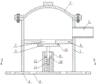
Fig. 1 is a structural sectional view of the carbon cylinder breather valve in a closed state.
Fig. 2 is a structural sectional view showing an open state of the breather valve for a carbon cylinder according to the present invention.
Fig. 3 is a sectional view taken along a-a in fig. 1 of a breather valve for a carbon cylinder according to the present invention.
The reference numbers in the drawings are as follows: the valve comprises a valve body 1, a valve cover 2, a bottom plate 3, a first vent hole 4, a vent pipe 5, a valve plate 6, a second vent hole 7, a valve disc 8, a guide column 9, a guide seat 10, a spring 11, a baffle 12 and a sealing ring 13.
Detailed Description
The invention will be further explained with reference to the drawings and the detailed description below:
as shown in fig. 1 to 3, the breather valve for the carbon cylinder is mounted on a top cover of the carbon cylinder, and comprises a valve body 1, a valve plate 6 and an opening and closing mechanism;
the valve body 1 is a hollow cylinder, the upper end of the valve body 1 is hermetically provided with a valve cover 2, the lower end of the valve body 1 is hermetically and fixedly provided with a bottom plate 3, the bottom plate 3 is provided with a first vent hole 4, and the side surface of the upper part of the valve body 1 is communicated with a vent pipe 5;
the valve plate 6 is fixedly arranged in the valve body 1 in a sealing mode, the valve plate 6 is positioned below the vent pipe 5, and the middle of the valve plate 6 is provided with a second vent hole 7;
the mechanism that opens and shuts sets up between valve plate 6 and bottom plate 3, and the mechanism that opens and shuts comprises valve disc 8, guide post 9 and guide holder 10, valve disc 8 is discoid and the diameter of valve disc 8 is greater than the diameter of second through-hole 7, the vertical fixed setting of guide post 9 is at 8 lower surface middle parts of valve disc, guide holder 10 is the pipe form, and the vertical fixed setting of guide holder 10 is at 3 upper surface middle parts of bottom plate, and guide post 9 sliding sleeve closes in guide holder 10, is provided with spring 11 between guide post 9 and the guide holder 10.
The bottom plate 3 is provided with a plurality of mounting holes, the mounting holes are located on the outer side of the valve body 1, and the mounting holes are uniformly arranged on the circumference by taking the central axis of the bottom plate 3 as the circle center.
The first vent hole 4 is positioned between the valve body 1 and the guide seat 10.
The number of the first vent holes 4 is not less than four, and the first vent holes 4 are uniformly arranged on the circumference by taking the central axis of the bottom plate 3 as the center of a circle.
The upper part of the guide column 9 is provided with a baffle plate 12, and the baffle plate 12 is sleeved in the guide seat 10.
The spring 11 is sleeved on the guide post 9, one end of the spring 11 is propped against the lower surface of the baffle 12, and the other end of the spring 11 is propped against the upper surface of the bottom plate 3.
And a sealing ring 13 is arranged on the upper surface of the valve plate 6, and the diameter of the sealing ring 13 is larger than that of the second vent hole 7.
A carbon cylinder comprises the breather valve for the carbon cylinder.
A breather valve is arranged at the top of the carbon cylinder, when the pressure in the carbon cylinder is the same as the pressure of the outside air, the gravity of the valve disc 8 is supported by the elasticity of the spring 11, the valve disc 8 is jacked up by the spring 11, the valve disc 8 is propped against the valve plate 6, so that the second vent hole 7 is closed, and the tightness of the container is kept; when the pressure in the carbon cylinder is reduced, the spring 11 is compressed under the action of the atmospheric pressure, the valve disc 8 descends, the valve disc 8 is separated from the valve plate 6, the second vent hole 7 is opened, air enters the carbon cylinder and is communicated with the atmospheric pressure outside, the pressure in the container does not continuously descend, and the pressure in the tank is guaranteed to be stable. And then avoid the carbon jar body negative pressure to appear, ensure that whole water preparation system work is normal, improve work efficiency, prevent that the carbon jar from being inhaled flat, avoid causing the property loss.
The above-mentioned embodiments are merely preferred embodiments of the present invention, and not intended to limit the scope of the present invention, so that equivalent changes or modifications made by the structure, features and principles of the present invention should be included in the claims of the present invention.
Claims (8)
1. A breather valve for a carbon cylinder is mounted on a top cover of the carbon cylinder and comprises a valve body (1), and is characterized by further comprising a valve plate (6) and an opening and closing mechanism;
the valve body (1) is a hollow cylinder, the upper end of the valve body (1) is hermetically provided with a valve cover (2), the lower end of the valve body (1) is hermetically and fixedly provided with a bottom plate (3), a first vent hole (4) is formed in the bottom plate (3), and the side surface of the upper part of the valve body (1) is communicated with a vent pipe (5);
the valve plate (6) is fixedly arranged in the valve body (1) in a sealing manner, the valve plate (6) is positioned below the vent pipe (5), and a second vent hole (7) is formed in the middle of the valve plate (6);
the mechanism that opens and shuts sets up between valve plate (6) and bottom plate (3), and the mechanism that opens and shuts comprises valve disc (8), guide post (9) and guide holder (10), valve disc (8) are discoid and the diameter of valve disc (8) is greater than the diameter of second venthole (7), guide post (9) vertical fixed setting is in valve disc (8) lower surface middle part, guide holder (10) are the pipe form, and vertical fixed setting in bottom plate (3) upper surface middle part of guide holder (10), and guide post (9) slip registrate is in guide holder (10), is provided with spring (11) between guide post (9) and guide holder (10).
2. The breather valve for the carbon cylinder as recited in claim 1, wherein the bottom plate (3) is provided with a plurality of mounting holes, the mounting holes are located at the outer side of the valve body (1), and the mounting holes are uniformly arranged on the circumference of the bottom plate (3) by taking the central axis as the center of a circle.
3. A breather valve for a carbon cylinder according to claim 1, characterised in that the first venting hole (4) is located between the valve body (1) and the guide seat (10).
4. The breather valve for the carbon cylinder as recited in claim 3, wherein the number of the first vent holes (4) is not less than four, and the first vent holes (4) are uniformly arranged on the circumference of the bottom plate (3) by taking the central axis as the center of a circle.
5. The breather valve for the carbon cylinder as in claim 1, wherein a baffle plate (12) is arranged at the upper part of the guide post (9), and the baffle plate (12) is sleeved in the guide seat (10).
6. The breather valve for the carbon cylinder as in claim 5, wherein the spring (11) is sleeved on the guide post (9), one end of the spring (11) is abutted to the lower surface of the baffle plate (12), and the other end of the spring is abutted to the upper surface of the bottom plate (3).
7. The breather valve for the carbon cylinder, according to claim 1, wherein the valve plate (6) is provided with a sealing ring (13) on the upper surface, and the diameter of the sealing ring (13) is larger than that of the second vent hole (7).
8. A carbon cylinder comprising a breather valve for a carbon cylinder according to any one of claims 1 to 7.
Priority Applications (1)
| Application Number | Priority Date | Filing Date | Title |
|---|---|---|---|
| CN201920693291.5U CN210240686U (en) | 2019-05-15 | 2019-05-15 | Breather valve for carbon cylinder and carbon cylinder |
Applications Claiming Priority (1)
| Application Number | Priority Date | Filing Date | Title |
|---|---|---|---|
| CN201920693291.5U CN210240686U (en) | 2019-05-15 | 2019-05-15 | Breather valve for carbon cylinder and carbon cylinder |
Publications (1)
| Publication Number | Publication Date |
|---|---|
| CN210240686U true CN210240686U (en) | 2020-04-03 |
Family
ID=69971069
Family Applications (1)
| Application Number | Title | Priority Date | Filing Date |
|---|---|---|---|
| CN201920693291.5U Active CN210240686U (en) | 2019-05-15 | 2019-05-15 | Breather valve for carbon cylinder and carbon cylinder |
Country Status (1)
| Country | Link |
|---|---|
| CN (1) | CN210240686U (en) |
Cited By (1)
| Publication number | Priority date | Publication date | Assignee | Title |
|---|---|---|---|---|
| CN113863385A (en) * | 2021-10-29 | 2021-12-31 | 长安大学 | Heat-preservation breathing well cover for air valve and using method |
-
2019
- 2019-05-15 CN CN201920693291.5U patent/CN210240686U/en active Active
Cited By (2)
| Publication number | Priority date | Publication date | Assignee | Title |
|---|---|---|---|---|
| CN113863385A (en) * | 2021-10-29 | 2021-12-31 | 长安大学 | Heat-preservation breathing well cover for air valve and using method |
| CN113863385B (en) * | 2021-10-29 | 2023-03-10 | 长安大学 | Heat-preservation breathing well cover for air valve and using method |
Similar Documents
| Publication | Publication Date | Title |
|---|---|---|
| CN210240686U (en) | Breather valve for carbon cylinder and carbon cylinder | |
| CN205605900U (en) | Positive negative pressure relief valve of low level spring | |
| CN200954046Y (en) | Air filtering device for water-drinking device | |
| CN106618229B (en) | Direct drinking machine water tank with sterile structure | |
| CN216155534U (en) | Activated carbon filtering device convenient for replacing filler | |
| CN212900361U (en) | Back-cleaning air valve | |
| CN210771383U (en) | Bearing box constant liquid level oil supply device | |
| CN216045660U (en) | Improved breather valve for hydrogen peroxide tank | |
| CN103735110B (en) | Purifying kettle | |
| CN208259316U (en) | A kind of outdoor cup with quick filtering function | |
| CN209361959U (en) | Suction filtration device is blown in a kind of rotation | |
| CN220536902U (en) | Non-contact sucking disc | |
| CN112915625A (en) | Air-removing filter | |
| CN201873079U (en) | Sterile breather valve applied in daily chemical production equipments | |
| CN218501564U (en) | Pipeline filter | |
| CN220276408U (en) | Self-sealing structure for upwards disassembling and replacing filter element | |
| CN219529839U (en) | Valve convenient to overhaul | |
| CN219119884U (en) | Sanitary fire-retardant breather valve for tank and sanitary storage tank | |
| CN201462124U (en) | Rubber safety valve | |
| CN214829403U (en) | Contain NMP waste water treatment filtration adsorption equipment | |
| CN212718231U (en) | Flange-connected spring-loaded high-flow safety valve | |
| CN219149360U (en) | Fuel filter with gassing function | |
| CN107827170A (en) | A kind of active carbon filter | |
| CN215505959U (en) | Sealed compressed air filter | |
| CN205127514U (en) | Ink filtration equipment |
Legal Events
| Date | Code | Title | Description |
|---|---|---|---|
| GR01 | Patent grant | ||
| GR01 | Patent grant |