CN210240007U - Horizontal mixed flow pump is from inhaling pressure device that intakes - Google Patents
Horizontal mixed flow pump is from inhaling pressure device that intakes Download PDFInfo
- Publication number
- CN210240007U CN210240007U CN201920689235.4U CN201920689235U CN210240007U CN 210240007 U CN210240007 U CN 210240007U CN 201920689235 U CN201920689235 U CN 201920689235U CN 210240007 U CN210240007 U CN 210240007U
- Authority
- CN
- China
- Prior art keywords
- water
- pipe
- pressure barrel
- flow pump
- water inlet
- Prior art date
- Legal status (The legal status is an assumption and is not a legal conclusion. Google has not performed a legal analysis and makes no representation as to the accuracy of the status listed.)
- Active
Links
Images

Abstract
The utility model discloses a horizontal mixed flow pump self-priming water inlet pressure device, wherein one end of a water inlet pipe (1) is positioned below the liquid level of a water taking pool, the other end of the water inlet pipe extends into the pressure barrel (2) from the top of the pressure barrel and is communicated with the pressure barrel (2), one end of an overflow pipe (5) is arranged on the side wall of the top of the pressure barrel (2), and the other end of the overflow pipe is positioned below the liquid level of the water taking pool; a tap water pipe valve (4) is arranged on the side wall of the top of the other side of the pressure barrel (2), one end of the emptying pipe valve (6) is arranged on the side wall of the bottom of the pressure barrel (2), and the other end of the emptying pipe valve is positioned above the liquid level of the water taking pool; the horizontal mixed-flow pump overcomes the defect that the horizontal mixed-flow pump in the prior art can not be started normally by filling the pump cavity with water by self-flow, has the advantage that the highest point of the water inlet pipe is higher than the top surface of the pressure barrel, and avoids the siphon backflow situation of water flowing through the water inlet pipe after the barrel body is filled with water.
Description
Technical Field
The utility model relates to a pressure device intakes, more specifically horizontal mixed flow pump is from inhaling pressure device that intakes.
Background
The shape, impeller shape and performance of the mixed flow pump are between those of a centrifugal pump and an axial flow pump. The mixed flow pump is characterized in that the flow rate is larger than that of the centrifugal pump, but smaller than that of the axial flow pump; the lift is lower than that of a centrifugal pump, but higher than that of an axial flow pump. The horizontal mixed flow pump has the advantages of both centrifugal pump and axial flow pump, and has simple structure, light weight and convenient use and maintenance. Therefore, the horizontal mixed flow pump is widely applied to the occasions of farmland irrigation, drought resistance, waterlogging drainage, industrial and urban water supply and drainage and the like. In recent years, the country increases the construction investment of irrigation and water conservancy, and the irrigation and water conservancy project is more, and wherein miniature horizontal mixed flow pump has played an important role in irrigation and water conservancy irrigation and drainage pump station.
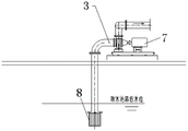
As shown in fig. 1: when the water pump mounting elevation is higher than the water level of the water suction pool, water is taken for a long time, the self-sucking pump is low in efficiency, or the self-sucking pump is not high in economy due to the fact that the cost is too high and the like, therefore, more horizontal mixed-flow pumps are used, but the horizontal mixed-flow pumps need to be mounted above the water surface, and the pump cavity cannot be filled with water by means of water self-flowing to normally start the pump. Usually, a vacuum pump is arranged for pumping vacuum to guide water into a water pump and then the water pump is started, or a bottom valve 8 is arranged at a water suction pipe opening, the bottom valve 8 can prevent water from flowing back to a water taking pool, at the moment, a water filling opening of a pump body or a water filling branch pipe is arranged in front of the pump to fill water into a water inlet pipe and a pump cavity, the water gradually fills the water inlet pipe, and a horizontal mixed-flow pump is started to pump water after the pump cavity is filled with water, so that the operation is troublesome.
In the actual operation of a pump station, a bottom valve is maintained frequently, a horizontal mixed flow pump cannot be started due to water leakage of the bottom valve or cannot pump air due to failure of an accessed vacuum pump, and the like, so that the horizontal mixed flow pump cannot pump a low-water-level water body.
Disclosure of Invention
The utility model aims to overcome the shortcomings of the prior art and provide a horizontal mixed flow pump is from inhaling water inlet pressure device.
The utility model aims at being implemented through the following technical scheme: a horizontal mixed flow pump self-priming water inlet pressure device comprises a water inlet pipe, a pressure barrel, a water outlet pipe, a tap water pipe valve, an overflow pipe and an emptying pipe valve;
one end of the water inlet pipe is positioned below the liquid level of the water taking pool, the other end of the water inlet pipe extends into the pressure barrel from the top of the pressure barrel and is communicated with the pressure barrel, one end of the overflow pipe is arranged on the side wall of the top of the pressure barrel, and the other end of the overflow pipe is positioned below the liquid level of the water taking pool;
a tap water pipe valve is arranged on the side wall of the top of the other side of the pressure barrel,
one end of the emptying pipe valve is arranged on the side wall of the bottom of the pressure barrel, and the other end of the emptying pipe valve is positioned above the liquid level of the water taking pool;
one end of the water outlet pipe is arranged on the side wall of the bottom of the pressure barrel, and the other end of the water outlet pipe is connected with the horizontal mixed flow pump.
In the above technical scheme: the caliber of the overflow pipe is not less than that of the tap water pipe valve.
In the above technical scheme: the aperture of the emptying pipe valve is larger than that of the tap water pipe valve.
In the above technical scheme: the tap water pipe valve is communicated with an external tap water pipe network.
In the above technical scheme: the highest point of the water inlet pipe is higher than the top surface of the pressure barrel.
The utility model has the advantages of as follows: 1. the utility model provides an overflow pipe installs at pressure bucket top lateral wall, has reduced the gaseous volume of whole pipeline that absorbs water, and the water pump can accomplish by the negative pressure more reasonable swiftly and absorb water to the process that the malleation was drawn water.
2. The utility model provides a below inlet tube one end stretched into water intaking pond liquid level, the other end passed the pressure barrel top surface and extended to the inside bottom of pressure barrel staving, reducible inlet channel hydraulic loss, just the inlet tube highest point be higher than the pressure barrel top surface, avoided the staving to fill the water after, the siphon refluence condition takes place for rivers through the inlet tube.
3. The utility model discloses need not complicated automatic monitoring control, but can realize that horizontal mixed flow pump start-up operation is the simplest, the not high area of the operation management level of being convenient for also can use.
Drawings
Fig. 1 is a schematic structural diagram of a water inlet pressure device in the prior art.
Fig. 2 is a schematic view of the overall structure of the present invention.
In the figure: the device comprises a water inlet pipe 1, a pressure barrel 2, a water outlet pipe 3, a tap water pipe valve 4, an overflow pipe 5, an emptying pipe valve 6, a horizontal mixed flow pump 7 and a bottom valve 8. The arrows in the figure indicate the direction of the water flow.
Detailed Description
The embodiments of the present invention will be described in detail with reference to the accompanying drawings, but they are not to be construed as limiting the invention, and are presented by way of example only, and the advantages of the invention will become more apparent and can be easily understood by description.
Referring to FIG. 2: a horizontal mixed flow pump is from inhaling water inlet pressure device, it includes the inlet tube 1, the pressure barrel 2, the outlet pipe 3, the running water pipe valve 4, the overflow pipe 5 and the blow-down pipe valve 6; one end of the water inlet pipe 1 is positioned below the liquid level of the water taking pool, the other end of the water inlet pipe extends into the pressure barrel 2 from the top of the pressure barrel and is communicated with the pressure barrel 2, one end of the overflow pipe 5 is arranged on the side wall of the top of the pressure barrel 2, and the other end of the overflow pipe is positioned below the liquid level of the water taking pool; a tap water pipe valve 4 is arranged on the side wall of the top of the other side of the pressure barrel 2,
one end of the emptying pipe valve 6 is arranged on the side wall of the bottom of the pressure barrel 2, and the other end is positioned above the liquid level of the water taking pool.
One end of the water outlet pipe 3 is arranged on the side wall of the bottom of the pressure barrel 2, and the other end of the water outlet pipe 3 is connected with the horizontal mixed flow pump.
The caliber of the overflow pipe 5 is not less than that of the tap water pipe valve 4; the aperture of the emptying pipe valve 6 is larger than the aperture of the tap water pipe valve 4; the tap water pipe valve 4 is communicated with an external tap water pipe network. The highest point of the water inlet pipe 1 is higher than the top surface of the pressure barrel 2.
The pressure barrel 2 is a cylindrical tank body, and the top surface, the bottom surface and the side wall cylindrical surface are directly welded into a whole by adopting equal-thickness steel plates, so that the economic cost is reduced while the processing is convenient.
1 one end of inlet tube stretch into below the pond liquid level of fetching water, the other end passes 2 top surfaces of pressure bucket and extend to 2 inside bottom ends of pressure bucket, the inlet tube highest point be higher than 2 top surfaces of pressure bucket.
The overflow pipe 5 is arranged on the side wall of the top of the pressure barrel, the other end of the overflow pipe 5 extends into the water taking pool below the liquid level, and the pipe diameter of the overflow pipe 5 is equal to or larger than that of a tap water pipe.
The utility model discloses a concrete operation process as follows: before the horizontal mixed-flow pump 7 is started, the tap water pipe valve 4 is opened to inject water into the pressure barrel 2, when the pressure barrel 2 is full of water, the water level in the barrel does not rise any more because the caliber of the overflow pipe 5 is equal to or larger than the caliber of the tap water pipe valve 4, the surplus water flows into the water taking tank through the overflow pipe 5, and the water level in the pressure barrel 2 gradually drops after the horizontal mixed-flow pump 7 is started to operate.
In the figure 2, the air pressure from the surface A-A to the surface B-B is rapidly reduced to form negative pressure, water in the water taking pool rapidly rises to enter the pressure barrel 2 through the water inlet pipe 1, and after the pressure in the pressure barrel 2 reaches dynamic stability, the horizontal mixed flow pump 7 also rapidly completes the process from negative pressure water suction to positive pressure water suction, namely the starting process of the water pump is completed, and the water pump enters stable operation.
The utility model discloses a horizontal mixed flow pump is from inhaling water pressure device, blow-down pipe valve 6 install at 2 bottom lateral walls of pressure vessel, 6 other ends of blow-down pipe valve more than the water intaking pond liquid level, 6 bores of blow-down pipe valve are greater than 4 bores of running water pipe valve, can regularly or at any time wash 2 insides of pressure vessel, open 6 valves of blow-down pipe valve during washing, utilize running water pipe valve 4 to carry out the washing of draining.
The above-mentioned parts not described in detail are prior art.
Claims (5)
1. The utility model provides a horizontal mixed flow pump is from inhaling pressure device that intakes which characterized in that: the device comprises a water inlet pipe (1), a pressure barrel (2), a water outlet pipe (3), a tap water pipe valve (4), an overflow pipe (5) and a vent pipe valve (6);
one end of the water inlet pipe (1) is positioned below the liquid level of the water taking pool, the other end of the water inlet pipe extends into the pressure barrel (2) from the top of the pressure barrel and is communicated with the pressure barrel (2), one end of the overflow pipe (5) is arranged on the side wall of the top of the pressure barrel (2), and the other end of the overflow pipe is positioned below the liquid level of the water taking pool;
a tap water pipe valve (4) is arranged on the side wall of the top of the other side of the pressure barrel (2),
one end of the emptying pipe valve (6) is arranged on the side wall of the bottom of the pressure barrel (2), and the other end of the emptying pipe valve is positioned above the liquid level of the water taking pool;
one end of the water outlet pipe (3) is arranged on the side wall of the bottom of the pressure barrel (2), and the other end of the water outlet pipe (3) is connected with the horizontal mixed flow pump.
2. The horizontal mixed-flow pump self-priming water inlet pressure device according to claim 1, characterized in that: the caliber of the overflow pipe (5) is not less than that of the tap water pipe valve (4).
3. The horizontal mixed-flow pump self-priming water inlet pressure device according to claim 1 or 2, characterized in that: the aperture of the emptying pipe valve (6) is larger than that of the tap water pipe valve (4).
4. The horizontal mixed-flow pump self-priming water inlet pressure device according to claim 3, characterized in that: the tap water pipe valve (4) is communicated with an external tap water pipe network.
5. The horizontal mixed flow pump self-priming water inlet pressure device according to claim 4, characterized in that: the highest point of the water inlet pipe (1) is higher than the top surface of the pressure barrel (2).
Priority Applications (1)
| Application Number | Priority Date | Filing Date | Title |
|---|---|---|---|
| CN201920689235.4U CN210240007U (en) | 2019-05-15 | 2019-05-15 | Horizontal mixed flow pump is from inhaling pressure device that intakes |
Applications Claiming Priority (1)
| Application Number | Priority Date | Filing Date | Title |
|---|---|---|---|
| CN201920689235.4U CN210240007U (en) | 2019-05-15 | 2019-05-15 | Horizontal mixed flow pump is from inhaling pressure device that intakes |
Publications (1)
| Publication Number | Publication Date |
|---|---|
| CN210240007U true CN210240007U (en) | 2020-04-03 |
Family
ID=69969977
Family Applications (1)
| Application Number | Title | Priority Date | Filing Date |
|---|---|---|---|
| CN201920689235.4U Active CN210240007U (en) | 2019-05-15 | 2019-05-15 | Horizontal mixed flow pump is from inhaling pressure device that intakes |
Country Status (1)
| Country | Link |
|---|---|
| CN (1) | CN210240007U (en) |
Cited By (1)
| Publication number | Priority date | Publication date | Assignee | Title |
|---|---|---|---|---|
| CN113236574A (en) * | 2021-05-26 | 2021-08-10 | 铜陵有色金属集团股份有限公司 | Automatic control device and method for preventing self-priming pump from air binding |
-
2019
- 2019-05-15 CN CN201920689235.4U patent/CN210240007U/en active Active
Cited By (1)
| Publication number | Priority date | Publication date | Assignee | Title |
|---|---|---|---|---|
| CN113236574A (en) * | 2021-05-26 | 2021-08-10 | 铜陵有色金属集团股份有限公司 | Automatic control device and method for preventing self-priming pump from air binding |
Similar Documents
| Publication | Publication Date | Title |
|---|---|---|
| CN201292951Y (en) | Negative pressure water box pumping device | |
| CN210240007U (en) | Horizontal mixed flow pump is from inhaling pressure device that intakes | |
| CN204082565U (en) | Vacuum water diversion centrifugal pump device | |
| CN211116652U (en) | Water pumper for hydraulic engineering irrigation | |
| CN207454290U (en) | A kind of centrifugal pump drainage tank | |
| CN213369449U (en) | Fish bowl overflow offal circulating device | |
| CN205190237U (en) | Self priming pump system for sewage treatment | |
| CN203113495U (en) | Drainage device used for oxygen steaming tank | |
| CN207728576U (en) | Pump negative pressure self-sucking pot | |
| CN207526696U (en) | Vacuum self-priming apparatus | |
| CN209557269U (en) | A kind of improved mixed flow pump | |
| CN212672064U (en) | Vacuum water absorption auxiliary device of centrifugal water pump | |
| CN206477428U (en) | A kind of high suction depth automatic vacuum sewage pump system | |
| CN207920894U (en) | A kind of device increasing water pump suction lift | |
| CN201062583Y (en) | Sewage pump and sewage pipe evacuation water diversion system | |
| CN219974833U (en) | Automatic water diversion device of coal mine centrifugal pump | |
| CN215109512U (en) | Water suction device of centrifugal pump | |
| CN215672910U (en) | Negative pressure device of dosing lift pump | |
| CN2659982Y (en) | Self-suction water feeder | |
| CN207660081U (en) | Configure the storage pond of emptying device | |
| CN220101499U (en) | Automatic emptying irrigation water diversion device | |
| CN202990093U (en) | Drain system for steamed oxygen pool | |
| CN211488974U (en) | Siphon adder for CTP cleaning equipment | |
| CN204491730U (en) | Non-tower water feeder | |
| CN209005345U (en) | A kind of vacuum tank with filtering function |
Legal Events
| Date | Code | Title | Description |
|---|---|---|---|
| GR01 | Patent grant | ||
| GR01 | Patent grant |