CN210232533U - Grinding device for die manufacturing - Google Patents
Grinding device for die manufacturing Download PDFInfo
- Publication number
- CN210232533U CN210232533U CN201920978958.6U CN201920978958U CN210232533U CN 210232533 U CN210232533 U CN 210232533U CN 201920978958 U CN201920978958 U CN 201920978958U CN 210232533 U CN210232533 U CN 210232533U
- Authority
- CN
- China
- Prior art keywords
- fixedly connected
- shell
- fixed
- water tank
- fan
- Prior art date
- Legal status (The legal status is an assumption and is not a legal conclusion. Google has not performed a legal analysis and makes no representation as to the accuracy of the status listed.)
- Active
Links
Images

Abstract
The utility model discloses a grinding device for mould manufacturing, including the set casing, the fixedly connected with cylinder of mid point department at set casing top, the bottom of cylinder run through the set casing and extend to its inside fixedly connected with fly leaf, the fixedly connected with rotating electrical machines of mid point department of fly leaf bottom, the rotatory pivot of fixedly connected with on the rotating electrical machines output shaft. The utility model discloses a water tank, the filler, the lid adds water, the fan, the blast pipe, the breathing pipe, the fixed head, the fixed plate, the supporting shoe, the threaded rod, press from both sides tight piece, the bin outlet, collect the shell, lead to the groove, mutually supporting of connecting block and handle, the effect of the dust removal of being convenient for has been realized, the problem of the common grinding device that is used for the mould to make dust removal of being not convenient for has been solved, produce a large amount of dust and metal particle when having avoided polishing the mould, thereby avoid influencing staff's healthy, the phenomenon of displacement appears in the mould when avoiding polishing simultaneously, bring very big facility for the user.
Description
Technical Field
The utility model relates to the technical field of molds, in particular to a polishing device for mold manufacturing.
Background
Dies, various moulds and tools for obtaining the desired products by injection, blow, extrusion, die-casting or forging, smelting, stamping, etc. in industrial production, in short, a die is a tool for making shaped articles, which tool is composed of various parts, and different dies are composed of different parts. The processing of the appearance of an article is realized mainly through the change of the physical state of a formed material. The prime has the title of "the mother of industry", the mould need use grinding device to polish it in the engineering of processing manufacturing, the processing is not convenient for remove dust to common grinding device who is used for the mould to make, can produce a large amount of dusts and metal particle to the mould in-process of polishing, the staff inhales for a long time and causes respiratory disease easily, and dust and metal particle still can influence operational environment, also can lead to grinding device's life to reduce for a long time, the phenomenon of displacement can appear in the mould when polishing moreover, thereby influence the quality of polishing, bring very big inconvenience for the user.
SUMMERY OF THE UTILITY MODEL
An object of the utility model is to provide a grinding device for mould is made possesses the advantage of being convenient for remove dust, has solved the problem that common grinding device for mould is made is not convenient for remove dust.
In order to achieve the above object, the utility model provides a following technical scheme: a polishing device for die manufacturing comprises a fixed shell, wherein a cylinder is fixedly connected to the midpoint of the top of the fixed shell, the bottom of the cylinder penetrates through the fixed shell and extends to the inner portion of the fixed shell and is fixedly connected with a movable plate, a rotating motor is fixedly connected to the midpoint of the bottom of the movable plate, a rotating shaft is fixedly connected to an output shaft of the rotating motor, a polishing disc is fixedly connected to the bottom end of the rotating shaft, dust removing devices are arranged on the left side and the right side of the fixed shell and correspond to the positions of the polishing disc, a fixing device is fixedly connected to the inner wall of the fixed shell and is positioned below the polishing disc, a collecting shell is arranged at the bottom of the inner wall of the fixed shell and is positioned below the fixing device, a through groove is formed in the right side of the fixed shell and corresponds to the position of the collecting shell, a connecting block is fixedly connected to the right side of the collecting shell, and a, the front surface of the fixed shell is provided with a fixed door;
the dust removal device comprises a water tank, one side of the water tank, which is close to the fixed shell, is fixedly connected with the fixed shell, the top of the left side of the water tank is provided with a water feeding port, the bottom of the left side of the water tank is provided with a drainage cover, the top of the water tank is fixedly connected with a fan, the left side of the fan is fixedly connected with an exhaust pipe which is communicated with the fan, one end of the exhaust pipe, which is far away from the fan, penetrates through the water tank and extends into the water tank, the right side of the fan is fixedly connected with an air suction pipe which is communicated with the fan, and one end;
fixing device includes the fixed plate, the surface of fixed plate and the inner wall fixed connection of set casing, the equal fixedly connected with supporting shoe in the left and right sides at fixed plate top, the equal threaded connection in one side that two supporting shoes kept away from each other has the threaded rod, one side that the threaded rod is close to the mill dish runs through the supporting shoe and extends to its outside fixedly connected with and presss from both sides tight piece, the bin outlet with collection shell looks adaptation is seted up and is collected to the bottom of fixed plate and the position that corresponds the collection shell.
Preferably, the top of the collecting case and the bottom of the fixing plate contact each other, and the bottom of the collecting case and the bottom of the inner wall of the fixing case contact each other.
Preferably, the left side of the handle and the right side of the stationary case are in contact with each other.
Preferably, the surface of the movable plate is slidably connected with the inner wall of the fixed shell.
Preferably, one side of the fixed head, which is far away from the polishing disc, is fixedly connected with an ejector block, and one side of the ejector block, which is close to the inner wall of the fixed shell, is fixedly connected with the inner wall of the fixed shell.
Compared with the prior art, the beneficial effects of the utility model are as follows:
1. the utility model discloses a water tank, the filler, the water cap, the fan, the blast pipe, the breathing pipe, the fixed head, the fixed plate, the supporting shoe, the threaded rod, press from both sides tight piece, the bin outlet, collect the shell, lead to the groove, mutually supporting of connecting block and handle, the effect of being convenient for remove dust has been realized, the problem of removing dust is not convenient for to the common grinding device who is used for the mould to make has been solved, produce a large amount of dust and metal particle when having avoided polishing the mould, thereby avoid influencing staff's healthy, the quality of operational environment is improved, the phenomenon of displacement appears in the mould when avoiding polishing simultaneously, grinding device's life has been improved, bring very big facility for the user.
2. The utility model discloses a set up the kicking block, played the effect of firm fixed head.
Drawings
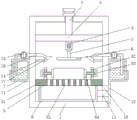
FIG. 1 is a structural section view in elevation of the present invention;
FIG. 2 is a sectional view of the dust removing device of the present invention;
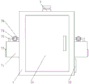
fig. 3 is a schematic structural diagram of the front view of the present invention.
In the figure: the device comprises a fixed shell 1, a cylinder 2, a movable plate 3, a rotating motor 4, a rotating shaft 5, a polishing disc 6, a dust removal device 7, a water tank 71, a water filling opening 72, a drainage cover 73, a fan 74, an exhaust pipe 75, an air suction pipe 76, a fixed head 77, a fixed device 8, a fixed plate 81, a supporting block 82, a threaded rod 83, a clamping block 84, a discharge opening 85, a collecting shell 9, a through groove 10, a connecting block 11, a handle 12, a fixed door 13 and a jacking block 14.
Detailed Description
The technical solutions in the embodiments of the present invention will be described clearly and completely with reference to the accompanying drawings in the embodiments of the present invention, and it is obvious that the described embodiments are only some embodiments of the present invention, not all embodiments. Based on the embodiments in the present invention, all other embodiments obtained by a person skilled in the art without creative work belong to the protection scope of the present invention.
Referring to fig. 1 or fig. 3, a polishing device for mold manufacturing comprises a fixed shell 1, a cylinder 2 is fixedly connected to a midpoint of a top of the fixed shell 1, a movable plate 3 is fixedly connected to a bottom of the cylinder 2, the bottom of the cylinder extends through the fixed shell 1 and extends to an inside of the fixed shell 1, a surface of the movable plate 3 is slidably connected to an inner wall of the fixed shell 1, a rotating motor 4 is fixedly connected to a midpoint of a bottom of the movable plate 3, a rotating shaft 5 is fixedly connected to an output shaft of the rotating motor 4, a polishing disc 6 is fixedly connected to a bottom end of the rotating shaft 5, a dust removing device 7 is disposed on left and right sides of the fixed shell 1 and corresponding to the polishing disc 6, a fixing device 8 is fixedly connected to an inner wall of the fixed shell 1 and located below the polishing disc 6, a collecting shell 9 is disposed on a bottom of an inner wall of the fixed shell 1 and located below the fixing device 8, collect the right side fixedly connected with connecting block 11 of shell 9, the outside fixedly connected with handle 12 that set casing 1 and logical groove 10 and extend to logical groove 10 is run through on the right side of connecting block 11, the left side of handle 12 and the right side of set casing 1 contact each other, and the front of set casing 1 is provided with fixed door 13.
Referring to fig. 1-2, the dust removing device 7 includes a water tank 71, one side of the water tank 71 close to the stationary housing 1 is fixedly connected to the stationary housing 1, a water inlet 72 is formed in the top of the left side of the water tank 71, a water discharge cover 73 is disposed at the bottom of the left side of the water tank 71, a fan 74 is fixedly connected to the top of the water tank 71, a left side of the fan 74 is fixedly connected to an exhaust pipe 75 communicated with the fan 74, one end of the exhaust pipe 75 far away from the fan 74 penetrates through the water tank 71 and extends into the water tank, a right side of the fan 74 is fixedly connected to an air suction pipe 76 communicated with the fan, one end of the air suction pipe 76 far away from the fan 74 penetrates through the stationary housing 1 and extends into the stationary housing 77, one side of the stationary head 77 far away from the polishing disc 6 is fixedly connected to a top block 14, one side of the top.
Referring to fig. 1-3, the fixing device 8 includes a fixing plate 81, a surface of the fixing plate 81 is fixedly connected to an inner wall of the fixing housing 1, a top of the collecting housing 9 is in contact with a bottom of the fixing plate 81, a bottom of the collecting housing 9 is in contact with a bottom of the inner wall of the fixing housing 1, supporting blocks 82 are fixedly connected to left and right sides of the top of the fixing plate 81, threaded rods 83 are respectively connected to two sides of the supporting blocks 82 away from each other, one side of each threaded rod 83 close to the polishing disk 6 penetrates through the supporting blocks 82 and extends to an outer portion of the supporting block 84, the threaded rods 83 and the clamping blocks 84 are arranged to fix and stabilize the mold, so as to prevent the mold from shifting during polishing, a discharge port 85 matched with the collecting housing 9 is formed at a position corresponding to the bottom of the fixing plate 81, and a drain port 85 matched with the collecting housing 9 is formed, Fan 74, blast pipe 75, breathing pipe 76, fixed head 77, fixed plate 81, supporting shoe 82, threaded rod 83, press from both sides tight piece 84, bin outlet 85, collect shell 9, lead to groove 10, mutually supporting of connecting block 11 and handle 12, the effect of the dust removal of being convenient for has been realized, the problem of the dust removal of being not convenient for of the common grinding device who is used for the mould to make has been solved, produce a large amount of dust and metal particle when having avoided polishing the mould, thereby avoid influencing staff's healthy, the quality of operational environment is improved, the phenomenon of displacement appears in the mould when avoiding polishing simultaneously, grinding device's life has been improved, bring very big facility for the user.
When the dust removal device is used, the fixed door 13 is opened, a mold is placed on the fixed plate 81, the threaded rod 83 is rotated, the threaded rod 83 drives the clamping block 84 to fixedly clamp the mold, then the air cylinder 2 is started, the air cylinder 2 drives the movable plate 3 to move downwards, the movable plate 3 drives the rotating motor 4 to move downwards, meanwhile, the rotating motor 4 is started, the rotating motor 4 drives the polishing disc 6 to rotate through the rotating shaft 5, the mold is polished, the fan 74 is started, the fan 74 enables dust to be discharged into the water inlet tank 71 through the mutual matching of the fixed head 77, the air suction pipe 76 and the exhaust pipe 75, metal particles generated by polishing are discharged into the collecting shell 9 through the discharge port 85, the dust removal effect is achieved, when the metal particles in the collecting shell 9 need to be treated, the handle 12 is pulled rightwards, the handle 12 drives the collecting shell 9 to move rightwards through the connecting block 11, so that the collecting shell 9 is drawn out from the fixed shell 1.
In summary, the following steps: this a grinding device for mould manufacturing, through the water tank 71, filler 72, drainage lid 73, fan 74, blast pipe 75, breathing pipe 76, fixed head 77, fixed plate 81, supporting shoe 82, threaded rod 83, press from both sides tight piece 84, bin outlet 85, collect shell 9, logical groove 10, connecting block 11 and handle 12 mutually support, solved the problem that the common grinding device for mould manufacturing is not convenient for remove dust.
Although embodiments of the present invention have been shown and described, it will be appreciated by those skilled in the art that changes, modifications, substitutions and alterations can be made in these embodiments without departing from the principles and spirit of the invention, the scope of which is defined in the appended claims and their equivalents.
Claims (5)
1. A grinding device for mould manufacturing, includes set casing (1), its characterized in that: the device is characterized in that a cylinder (2) is fixedly connected to the middle point of the top of the fixed shell (1), the bottom of the cylinder (2) penetrates through the fixed shell (1) and extends to the inner portion of the fixed shell (1) and is fixedly connected with a movable plate (3), a rotating motor (4) is fixedly connected to the middle point of the bottom of the movable plate (3), a rotating shaft (5) is fixedly connected to an output shaft of the rotating motor (4), a polishing disc (6) is fixedly connected to the bottom end of the rotating shaft (5), dust removing devices (7) are respectively arranged on the left side and the right side of the fixed shell (1) and correspond to the positions of the polishing disc (6), a fixing device (8) is fixedly connected to the inner wall of the fixed shell (1) and is positioned below the polishing disc (6), a collecting shell (9) is arranged on the bottom of the inner wall of the fixed shell (1) and is positioned below the fixing device (8), a through groove, a connecting block (11) is fixedly connected to the right side of the collecting shell (9), the right side of the connecting block (11) penetrates through the fixing shell (1) and the through groove (10) and extends to the outside of the through groove (10) to be fixedly connected with a handle (12), and a fixing door (13) is arranged on the front side of the fixing shell (1);
the dust removal device (7) comprises a water tank (71), one side, close to the fixed shell (1), of the water tank (71) is fixedly connected with the fixed shell (1), a water filling port (72) is formed in the top of the left side of the water tank (71), a drainage cover (73) is arranged at the bottom of the left side of the water tank (71), a fan (74) is fixedly connected to the top of the water tank (71), an exhaust pipe (75) communicated with the fan (74) is fixedly connected to the left side of the fan (74), one end, far away from the fan (74), of the exhaust pipe (75) penetrates through the water tank (71) and extends into the interior of the water tank, an air suction pipe (76) communicated with the exhaust pipe is fixedly connected to the right side of the fan (74), and one end, far away from the fan (74), of the air suction pipe (;
fixing device (8) are including fixed plate (81), the surface of fixed plate (81) and the inner wall fixed connection of set casing (1), the equal fixedly connected with supporting shoe (82) in the left and right sides at fixed plate (81) top, the equal threaded connection in one side that two supporting shoes (82) kept away from each other has threaded rod (83), one side that threaded rod (83) are close to make the mill dish (6) runs through supporting shoe (82) and extends to its outside fixedly connected with and presss from both sides tight piece (84), the bin outlet (85) with collection shell (9) looks adaptation is seted up and is collected to the bottom of fixed plate (81) and the position of collecting shell (9) that corresponds.
2. A grinding device for use in mold manufacturing according to claim 1, wherein: the top of the collecting shell (9) is contacted with the bottom of the fixing plate (81), and the bottom of the collecting shell (9) is contacted with the bottom of the inner wall of the fixing shell (1).
3. A grinding device for use in mold manufacturing according to claim 1, wherein: the left side of the handle (12) is in contact with the right side of the fixed shell (1).
4. A grinding device for use in mold manufacturing according to claim 1, wherein: the surface of the movable plate (3) is connected with the inner wall of the fixed shell (1) in a sliding manner.
5. A grinding device for use in mold manufacturing according to claim 1, wherein: one side fixedly connected with kicking block (14) of beating dish (6) is kept away from to fixed head (77), one side that kicking block (14) are close to set casing (1) inner wall is with the inner wall fixed connection of set casing (1).
Priority Applications (1)
| Application Number | Priority Date | Filing Date | Title |
|---|---|---|---|
| CN201920978958.6U CN210232533U (en) | 2019-06-27 | 2019-06-27 | Grinding device for die manufacturing |
Applications Claiming Priority (1)
| Application Number | Priority Date | Filing Date | Title |
|---|---|---|---|
| CN201920978958.6U CN210232533U (en) | 2019-06-27 | 2019-06-27 | Grinding device for die manufacturing |
Publications (1)
| Publication Number | Publication Date |
|---|---|
| CN210232533U true CN210232533U (en) | 2020-04-03 |
Family
ID=69988015
Family Applications (1)
| Application Number | Title | Priority Date | Filing Date |
|---|---|---|---|
| CN201920978958.6U Active CN210232533U (en) | 2019-06-27 | 2019-06-27 | Grinding device for die manufacturing |
Country Status (1)
| Country | Link |
|---|---|
| CN (1) | CN210232533U (en) |
Cited By (3)
| Publication number | Priority date | Publication date | Assignee | Title |
|---|---|---|---|---|
| CN111890183A (en) * | 2020-08-03 | 2020-11-06 | 赵恒伟 | Auxiliary mechanism for researching and matching of automobile outer surrounding die closing process |
| CN112059837A (en) * | 2020-09-14 | 2020-12-11 | 杭州丰衡机电有限公司 | Automatic grinding machine for die machining |
| CN112320206A (en) * | 2020-09-27 | 2021-02-05 | 靖州喜乐购电子商务有限公司 | Electronic commerce logistics conveying device and using method thereof |
-
2019
- 2019-06-27 CN CN201920978958.6U patent/CN210232533U/en active Active
Cited By (5)
| Publication number | Priority date | Publication date | Assignee | Title |
|---|---|---|---|---|
| CN111890183A (en) * | 2020-08-03 | 2020-11-06 | 赵恒伟 | Auxiliary mechanism for researching and matching of automobile outer surrounding die closing process |
| CN111890183B (en) * | 2020-08-03 | 2021-09-24 | 濉溪泰高科技有限公司 | Auxiliary mechanism for researching and matching of automobile outer surrounding die closing process |
| CN112059837A (en) * | 2020-09-14 | 2020-12-11 | 杭州丰衡机电有限公司 | Automatic grinding machine for die machining |
| CN112320206A (en) * | 2020-09-27 | 2021-02-05 | 靖州喜乐购电子商务有限公司 | Electronic commerce logistics conveying device and using method thereof |
| CN112320206B (en) * | 2020-09-27 | 2022-05-17 | 靖州喜乐购电子商务有限公司 | Electronic commerce logistics conveying device and using method thereof |
Similar Documents
| Publication | Publication Date | Title |
|---|---|---|
| CN210232533U (en) | Grinding device for die manufacturing | |
| CN210415153U (en) | Mold equipment capable of effectively removing dust | |
| CN214080736U (en) | Grinding device for injection mold convenient to collect piece | |
| CN116619034A (en) | Automatic change machining mould | |
| CN214109854U (en) | Mould unhairing limit device | |
| CN208960531U (en) | A kind of dust-proof mold of decompression for metal bar processing | |
| CN208496579U (en) | A kind of injection mold beveler | |
| CN215903261U (en) | Polishing device for industrial mold | |
| CN113020995A (en) | A quick manual processing apparatus for mould contour machining | |
| CN213827269U (en) | Cutting device is used in mould production with heat dissipation function | |
| CN218052095U (en) | Melamine production dust collector | |
| CN211965125U (en) | Mould belt cleaning device for mould manufacturing | |
| CN218611585U (en) | Brake disc casting storehouse | |
| CN213702895U (en) | Grinding device for die manufacturing | |
| CN214080623U (en) | Portable foundry goods cleaner of polishing | |
| CN216098098U (en) | Polishing device for casting forging | |
| CN220162022U (en) | Deburring device for die production | |
| CN216542508U (en) | Accurate grinding machine is used in mould production | |
| CN216359493U (en) | Die positioning and polishing device for machine manufacturing | |
| CN219805894U (en) | Mould polishing structure | |
| CN212553159U (en) | Motor casing polisher for mould | |
| CN214448087U (en) | Efficient injection mold with dust removal function | |
| CN214109933U (en) | Grinding device is used in processing of frock mould of accurate spare part | |
| CN220675307U (en) | Sole pressing device for leather shoe production | |
| CN215434713U (en) | Automatic draw-out device of making an uproar that falls of injection molding machine |
Legal Events
| Date | Code | Title | Description |
|---|---|---|---|
| GR01 | Patent grant | ||
| GR01 | Patent grant |