CN210232294U - Quick positioning fixture of multiaspect processing - Google Patents
Quick positioning fixture of multiaspect processing Download PDFInfo
- Publication number
- CN210232294U CN210232294U CN201921200190.6U CN201921200190U CN210232294U CN 210232294 U CN210232294 U CN 210232294U CN 201921200190 U CN201921200190 U CN 201921200190U CN 210232294 U CN210232294 U CN 210232294U
- Authority
- CN
- China
- Prior art keywords
- seat
- positioning
- plate
- mounting
- locking mechanism
- Prior art date
- Legal status (The legal status is an assumption and is not a legal conclusion. Google has not performed a legal analysis and makes no representation as to the accuracy of the status listed.)
- Active
Links
Images


Abstract
The utility model discloses a quick positioning fixture for multi-surface processing, which comprises a fixture seat, a positioning seat arranged on the fixture seat and a locking mechanism, wherein the fixture seat comprises a seat plate and a vertical mounting plate, two sides of the mounting plate are fixedly provided with a fixed plate through screws, and the fixed plate is fixedly connected with the seat plate through screws; the locking mechanism is characterized in that the number of the positioning seats is five, two positioning seats are fixedly mounted on two sides of the mounting plate, the positioning seats are fixedly mounted on the front portion of the upper end of the seat plate, and the locking mechanism is five and is fixedly connected to the positioning seats through positioning blocks respectively. The utility model relates to a rationally, simple structure, convenient to use conveniently processes work piece machining's frock clamp, through reasonable design anchor clamps seat, is provided with five positioning seats on this anchor clamps seat, through the locating piece with locking mechanism fixed mounting in the positioning seat to the switching to the different faces when having made things convenient for processing the work piece.
Description
Technical Field
The utility model relates to a machining anchor clamps specifically say a quick positioning fixture of multiaspect processing.
Background
Tooling, namely process equipment: refers to the collective term for the various tools used in the manufacturing process. Comprises a cutter/clamp/mould/measuring tool/detecting tool/auxiliary tool/bench tool/station tool and the like; the tooling is a general abbreviation thereof.
The surface of a workpiece is processed quite commonly in machining, and during surface processing, the workpiece is positioned accurately, so that the processing quality can be ensured; if the positioning is unreasonable or the clamping is unreasonable, the processing quality is unstable, the rejection rate is high, and meanwhile, the working efficiency is low.
SUMMERY OF THE UTILITY MODEL
Therefore, in order to overcome the above insufficiency, the utility model provides a reasonable in design, simple structure, convenient to use, the frock clamp of conveniently processing work piece machining through reasonable design anchor clamps seat, is provided with five positioning seats on this anchor clamps seat, through the locating piece with locking mechanism fixed mounting in the positioning seat to the switching to the different faces when having made things convenient for the processing work piece.
The utility model is realized in such a way that a rapid positioning fixture with multi-surface processing is constructed, which comprises a fixture seat, a positioning seat arranged on the fixture seat and a locking mechanism,
the fixture seat comprises a seat plate and a vertical mounting plate, wherein fixing plates are fixedly mounted on two sides of the mounting plate through screws, and the fixing plates are fixedly connected with the seat plate through screws;
the number of the positioning seats is five, two positioning seats are fixedly arranged on two sides of the mounting plate, the positioning seats are fixedly arranged on the front part of the upper end of the seat plate,
the locking mechanisms are five in total and are fixedly connected to the positioning seat through the positioning blocks respectively.
Preferably, the locking mechanism comprises a mounting seat, side plates arranged on two sides of the mounting seat, two adjusting blocks which are arranged on the mounting seat and have adjustable intervals, and a clamping block arranged at the upper end of each adjusting block, wherein the side plates are fixedly connected with the mounting seat through screws, the adjusting blocks are arranged on the mounting seat in a clamping box mode and adjust the intervals between the two adjusting blocks through bolts, and the clamping blocks are arranged at the upper ends of the adjusting blocks through screws.
Preferably, the two sides of the lower end of the adjusting block are provided with L-shaped inner buckle plates matched with the mounting seat, the upper end of the adjusting block is provided with a transverse groove for mounting the clamping block, and a plurality of threaded holes convenient for adjusting the position of the mounting clamping block are formed in the transverse groove.
Preferably, the outer side surface of the positioning seat is provided with four limiting lugs arranged in a circular array.
Preferably, the positioning block is provided with a limiting groove matched with the limiting lug.
The utility model discloses following beneficial effect has:
the utility model relates to a rationally, simple structure, convenient to use is a frock clamp for machining, through reasonable design anchor clamps seat, is provided with five positioning seats on this anchor clamps seat, through the locating piece with locking mechanism fixed mounting in the positioning seat to the switching to the different faces when having made things convenient for the processing work piece.
The positioning seat is reasonably designed, so that the position accuracy of each locking mechanism can be guaranteed, the machining quality is guaranteed, meanwhile, the locking mechanism is reasonably designed, the locking mechanism is provided with two adjusting blocks with adjustable intervals, the adjusting blocks are also provided with mounting clamping blocks, so that the clamping of a machined workpiece is facilitated, and the positions of the mounting clamping blocks at the upper ends of the adjusting blocks are adjustable, so that the clamping of machined workpieces of various specifications is adapted, and the machining of the machined workpieces is facilitated;
the utility model discloses the structure is ingenious, and the installation is convenient with the dismantlement, is convenient for maintenance from now on, and easy manufacturing, low cost excellent in use effect.
Drawings
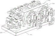
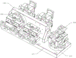
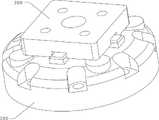
Fig. 1-2 are overall schematic views of the present invention;
FIG. 3 is a perspective view of the fixture seat mounting and positioning seat of the present invention;
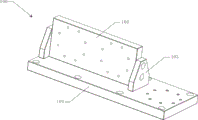
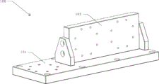
figures 4-5 are perspective views of the clamp base of the present invention;
FIG. 6 is a schematic view of the positioning block and positioning seat of the present invention;
fig. 7 is a perspective view of the locking mechanism of the present invention;
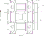
fig. 8 is a front view of the locking mechanism of the present invention;
fig. 9 is a top view of the locking mechanism of the present invention;
fig. 10 is a left side view of the locking mechanism of the present invention;
FIG. 11 is a cross-sectional view B-B of FIG. 9;
FIG. 12 is a perspective view of the adjusting block of the present invention;
in the figure: 100. a clamp seat; 101. a seat plate; 102. mounting a plate; 103. a fixing plate; 200. positioning seats; 300. positioning blocks; 400. a locking mechanism; 401. a mounting seat; 402. a side plate; 403. an adjusting block; 404. installing a clamping block; 405. a bolt; 406. a transverse groove; 407. an L-shaped inner buckle plate; 500. and (5) processing the workpiece.
Detailed Description
The present invention will be described in detail with reference to the accompanying drawings 1-12, wherein the technical solutions in the embodiments of the present invention are clearly and completely described, and it is obvious that the described embodiments are only some embodiments of the present invention, not all embodiments. Based on the embodiments in the present invention, all other embodiments obtained by a person skilled in the art without creative work belong to the protection scope of the present invention.
As shown in fig. 1 to 12, the present invention provides a multi-surface machining rapid positioning fixture, which comprises a fixture base 100, a positioning base 200 installed on the fixture base 100, and a locking mechanism 400,
the clamp seat 100 comprises a seat plate 101 and a vertical mounting plate 102, wherein fixing plates 103 are fixedly mounted on two sides of the mounting plate 102 through screws, and the fixing plates 103 are fixedly connected with the seat plate 101 through screws;
the number of the positioning seats 200 is five, two positioning seats 200 are fixedly arranged on two sides of the mounting plate 102, the positioning seats 200 are fixedly arranged on the front part of the upper end of the seat plate 101,
the number of the locking mechanisms 400 is five, and the locking mechanisms are fixedly connected to the positioning base 200 through the positioning blocks 300 respectively.
In this embodiment, the locking mechanism 400 includes a mounting seat 401, side plates 402 mounted on two sides of the mounting seat 401, two adjusting blocks 403 mounted on the mounting seat and having an adjustable distance therebetween, and a clamping block 404 mounted on an upper end of the adjusting block 403, wherein the side plates are fixedly connected to the mounting seat by screws, the adjusting block is mounted on the mounting seat in a clamping manner and has an adjustable distance therebetween by bolts 405, and the clamping block 404 is mounted on an upper end of the adjusting block 403 by screws.
In this embodiment, two sides of the lower end of the adjusting block 403 are provided with L-shaped inner fastening plates 407 matching with the mounting seat 401, the upper end of the adjusting block 403 is provided with a transverse groove 406 for mounting the clamping block 404, and a plurality of threaded holes facilitating position adjustment of the mounting clamping block 404 are formed in the transverse groove 406.
In this embodiment, the outer side surface of the positioning seat 200 is provided with four limiting convex blocks arranged in a circular array.
In the present embodiment, the positioning block 300 is provided with a limiting groove matched with the limiting bump.
The utility model relates to a positioning fixture for machining, when in use, a locking mechanism is arranged on a positioning seat through a positioning block, the positioning seat is fixedly arranged on a fixture seat, the clamping and positioning of a machined workpiece are realized through the locking mechanism, thereby facilitating the machining of the workpiece by external machining equipment,
when the locking mechanism is used, the distance between the two adjusting blocks is adjusted through the bolt, and the mounting clamping blocks are used for clamping, so that the stability and reliability of a machined workpiece are guaranteed.
The previous description of the disclosed embodiments is provided to enable any person skilled in the art to make or use the present invention. Various modifications to these embodiments will be readily apparent to those skilled in the art, and the generic principles defined herein may be applied to other embodiments without departing from the spirit or scope of the invention. Thus, the present invention is not intended to be limited to the embodiments shown herein but is to be accorded the widest scope consistent with the principles and novel features disclosed herein.
Claims (5)
1. The utility model provides a quick positioning fixture of multiaspect processing which characterized in that: comprises a clamp seat (100), a positioning seat (200) arranged on the clamp seat (100), and a locking mechanism (400),
the clamp seat (100) comprises a seat plate (101) and a vertical mounting plate (102), fixing plates (103) are fixedly mounted on two sides of the mounting plate (102) through screws, and the fixing plates (103) are fixedly connected with the seat plate (101) through screws;
the total number of the positioning seats (200) is five, two positioning seats (200) are fixedly arranged on two sides of the mounting plate (102), the positioning seats (200) are fixedly arranged on the front part of the upper end of the seat plate (101),
the number of the locking mechanisms (400) is five, and the locking mechanisms are fixedly connected to the positioning seat (200) through the positioning blocks (300) respectively.
2. The multi-faceted fast positioning jig according to claim 1, further comprising: locking mechanism (400) include mount pad (401), install in curb plate (402) of mount pad (401) both sides, two install on the mount pad and interval adjustable regulating block (403) to and install clamp splice (404) in regulating block (403) upper end, the curb plate passes through screw and mount pad fixed connection, the regulating block is installed in the mount pad with the card box mode and is adjusted the interval between two regulating blocks through bolt (405), clamp splice (404) are through screw mounting in regulating block (403) upper end.
3. The multi-faceted fast positioning jig of claim 2, further comprising: the adjusting block is characterized in that L-shaped inner buckling plates (407) matched with the mounting base (401) are arranged on two sides of the lower end of the adjusting block (403), meanwhile, a transverse groove (406) for mounting the clamping block (404) is formed in the upper end of the adjusting block (403), and a plurality of threaded holes facilitating position adjustment of the mounting clamping block (404) are formed in the transverse groove (406).
4. The multi-faceted fast positioning jig according to claim 1, further comprising: the outer side face of the positioning seat (200) is provided with four limiting lugs which are arranged in a circular array.
5. The multi-faceted rapid positioning fixture of claim 4, wherein: the positioning block (300) is provided with a limiting groove matched with the limiting lug.
Priority Applications (1)
| Application Number | Priority Date | Filing Date | Title |
|---|---|---|---|
| CN201921200190.6U CN210232294U (en) | 2019-07-29 | 2019-07-29 | Quick positioning fixture of multiaspect processing |
Applications Claiming Priority (1)
| Application Number | Priority Date | Filing Date | Title |
|---|---|---|---|
| CN201921200190.6U CN210232294U (en) | 2019-07-29 | 2019-07-29 | Quick positioning fixture of multiaspect processing |
Publications (1)
| Publication Number | Publication Date |
|---|---|
| CN210232294U true CN210232294U (en) | 2020-04-03 |
Family
ID=69992987
Family Applications (1)
| Application Number | Title | Priority Date | Filing Date |
|---|---|---|---|
| CN201921200190.6U Active CN210232294U (en) | 2019-07-29 | 2019-07-29 | Quick positioning fixture of multiaspect processing |
Country Status (1)
| Country | Link |
|---|---|
| CN (1) | CN210232294U (en) |
Cited By (1)
| Publication number | Priority date | Publication date | Assignee | Title |
|---|---|---|---|---|
| CN114714120A (en) * | 2022-05-13 | 2022-07-08 | 北京航臻科技有限公司 | Flexible multi-surface clamp for structural part |
-
2019
- 2019-07-29 CN CN201921200190.6U patent/CN210232294U/en active Active
Cited By (1)
| Publication number | Priority date | Publication date | Assignee | Title |
|---|---|---|---|---|
| CN114714120A (en) * | 2022-05-13 | 2022-07-08 | 北京航臻科技有限公司 | Flexible multi-surface clamp for structural part |
Similar Documents
| Publication | Publication Date | Title |
|---|---|---|
| CN212600493U (en) | Positioning tool for machining bearing seat | |
| CN210232294U (en) | Quick positioning fixture of multiaspect processing | |
| CN215393889U (en) | CNC is profile shapes clamping frock for numerical control machining center | |
| CN112775696B (en) | Tool for processing inclined plane of long-strip-shaped workpiece on common milling machine | |
| CN209754583U (en) | Structure for adjusting positioning center of vertical lathe clamp | |
| CN103157840B (en) | Method for end milling of double-slope workpiece | |
| CN212793761U (en) | Rectangle encloses frame welding frock | |
| CN216781139U (en) | Planer-type milling machine is used for rectifying large-scale sheet material clamping positioning tool | |
| CN217095839U (en) | Fixing clamp for processing plate-shaped part hole groove and outer contour | |
| CN210878676U (en) | Adjustable lathe work positioning and clamping device | |
| CN210281413U (en) | Tool for milling wedge-shaped notch on cylindrical workpiece | |
| CN210757163U (en) | Irregular part surface grinding machine anchor clamps | |
| CN212917784U (en) | Milling fixture | |
| CN212095899U (en) | Grinding machine fixture | |
| CN212946587U (en) | Clamp applied to sawing machine for machining annular workpiece | |
| CN210232254U (en) | Multipurpose flange milling surface clamp | |
| CN210189465U (en) | Plate workpiece grinding clamp | |
| CN212192193U (en) | Milling machine fixture | |
| CN218017219U (en) | Sheet part machining tool | |
| CN215469701U (en) | Special fixture for one-time clamping and processing of multi-body magnetic steel seat | |
| CN213053773U (en) | 45-degree surface machining tool for die | |
| CN210189466U (en) | Multi-step plane grinding clamp capable of reducing parallelism tolerance | |
| CN218253948U (en) | Lathe fixture | |
| CN211588827U (en) | Fixing clamp for electric spark machining of arc-shaped bend of semiconductor equipment part | |
| CN220330634U (en) | Quick clamping and change portable pipeline die core processing clamp |
Legal Events
| Date | Code | Title | Description |
|---|---|---|---|
| GR01 | Patent grant | ||
| GR01 | Patent grant | ||
| CP03 | Change of name, title or address |
Address after: 611700 No. 299, Tianba West Street, new economic Industrial Park, Chengdu modern industrial port, Pidu District, Chengdu City, Sichuan Province Patentee after: Chengdu Ruixue Fengtai Precision Electronics Co.,Ltd. Address before: No. 489, Qingma Road, south area of Chengdu modern industrial port, Pixian County, Chengdu, Sichuan 611700 Patentee before: CHENGDU RUIXUE PRECISION MACHINERY Co.,Ltd. |
|
| CP03 | Change of name, title or address |