CN210213978U - Adjustable high-precision feeder - Google Patents
Adjustable high-precision feeder Download PDFInfo
- Publication number
- CN210213978U CN210213978U CN201920760780.8U CN201920760780U CN210213978U CN 210213978 U CN210213978 U CN 210213978U CN 201920760780 U CN201920760780 U CN 201920760780U CN 210213978 U CN210213978 U CN 210213978U
- Authority
- CN
- China
- Prior art keywords
- unloading
- row
- adjustable high
- servo motor
- unloading pipe
- Prior art date
- Legal status (The legal status is an assumption and is not a legal conclusion. Google has not performed a legal analysis and makes no representation as to the accuracy of the status listed.)
- Active
Links
Images


Abstract
The utility model belongs to the technical field of the charging machine, especially, be an adjustable high accuracy charging machine including hoist mechanism and unloading mechanism, unloading mechanism installs the one end at hoist mechanism, unloading mechanism includes material distributing tank and unloading pipe, the unloading pipe welding is at the lower extreme of material distributing tank, the inside rotation of unloading pipe is connected with the row material cylinder, the surface of row material cylinder has seted up the relief groove, the surface of unloading pipe is fixed with servo motor through the bolt; through the inside row's of rotating material cylinder of connecting of unloading pipe for the inside material of feed dividing tank is discharged through the row's of expecting groove that row's material cylinder surface was seted up, has increased the inside material ration of feed dividing tank and has discharged, has increased the precision that the material was put in, arranges the material cylinder simultaneously and carries out the transmission through arranging material groove, servo motor and drive pulley, and servo motor's output shaft area drive pulley rotates, and drive pulley makes driven pulley group area arrange the material cylinder rotation through the belt.
Description
Technical Field
The utility model belongs to the technical field of the feeder, concretely relates to adjustable high accuracy feeder.
Background
The feeder for the device that the material circulation was delivered has advantages such as carry the distance length, the freight volume is big, continuous transport, and the operation is reliable moreover, easily realizes automation and centralized control, and traditional feeder is when using, and the material high accuracy is delivered poor stability, causes the material to deliver easily and appears the deviation, and the problem of phenomenon of hardening appears easily in the material after the lifting simultaneously.
SUMMERY OF THE UTILITY MODEL
For solving the above-mentioned problem that exists among the prior art, the utility model provides an adjustable high accuracy feeder has the material ration and delivers stably, and it is convenient that the material circulation is delivered simultaneously, and the material appears being convenient for after hardening to break up characteristics.
In order to achieve the above object, the utility model provides a following technical scheme: the utility model provides an adjustable high accuracy feeder, includes hoist mechanism and unloading mechanism, the one end at hoist mechanism is installed to unloading mechanism, unloading mechanism is including dividing material jar and unloading pipe, the welding of unloading pipe is at the lower extreme that divides the material jar, the inside rotation of unloading pipe is connected with row material cylinder, arrange the surface of material cylinder and seted up row material groove, the surface of unloading pipe has servo motor through the bolt fastening, driving pulley is installed to servo motor's output shaft, the one end of arranging the material cylinder is fixed with driven pulley group, just driving pulley and driven pulley group pass through the belt and connect.
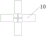
As a preferred technical scheme of the utility model, the strut frame is installed through the bolt in the inside of unloading mechanism, the top of strut frame is rotated and is connected with branch material flabellum.
As an optimized technical solution of the present invention, the material-separating fan blades are provided with four inclined thin plates, and the horizontal inclination angle of the four thin plates is 30 °.
As a preferred technical scheme of the utility model, the inside welding of unloading mechanism lower extreme has the bulk cargo net, the bulk cargo net is latticed structure, just the bulk cargo net is provided with two-layer altogether.
As an optimized technical scheme of the utility model, the intraduct row of unloading cylinder is provided with two, and every arrange the row's silo that the surface of arranging the material cylinder was seted up and be provided with eight.
As an optimized technical scheme of the utility model, the blow-off tank is bar structure, just the degree of depth of blow-off tank is the radial third of row's material cylinder.
As a preferred technical scheme of the utility model, driven pulley group is two belt pulley groove structures, driven pulley group's inboard race passes through the belt with servo motor and is connected, two driven pulley group's outside race passes through belt interconnect.
Compared with the prior art, the beneficial effects of the utility model are that:
1. through the inside row's of rotation material cylinder of connecting of unloading pipe, make the inside material of branch material jar discharge through the row's silo that row's material cylinder surface was seted up, the inside material ration of branch material jar is discharged has been increased, the precision that the material was put in has been increased, it passes through row's silo to arrange the material cylinder simultaneously, servo motor and drive pulley carry out the transmission, servo motor's output shaft area drive pulley rotates, the drive pulley makes driven pulley group rotate through the belt, driven pulley group takes row material cylinder to rotate in the inside of unloading pipe simultaneously, row's material cylinder pivoted convenience has been increased, the inside material of row's silo of being convenient for is put in.
2. Divide material flabellum and bulk cargo net through dividing material jar internally mounted for the material that enters into and divides the material jar inside strikes the surface of dividing the material flabellum, because divide the material flabellum and personally submit 30 contained angles with the level, make and divide the material flabellum to rotate after the material striking, make the material tentatively break up, avoid the material to appear the cubic after the hoist mechanism lifting, the bulk cargo net is installed in the below of dividing the material flabellum simultaneously, make the material fall behind through the bulk cargo net disperse once more, the material after the dispersion of being convenient for is discharged through arranging the material cylinder.
Drawings
The accompanying drawings are included to provide a further understanding of the invention, and are incorporated in and constitute a part of this specification, illustrate embodiments of the invention, and together with the description serve to explain the invention and not to limit the invention. In the drawings:
fig. 1 is a schematic structural view of the present invention;
FIG. 2 is a schematic view of a half-section structure of the blanking mechanism of the present invention;
FIG. 3 is a schematic structural view of a discharging tube and a discharging roller in the present invention;
FIG. 4 is a schematic view of the three-dimensional structure of the discharge roller of the present invention;
fig. 5 is a schematic structural view of a servo motor, a driving pulley and a driven pulley set in the present invention;
FIG. 6 is a schematic side view of the fan blades of the present invention;
fig. 7 is a schematic top view of the fan blades of the present invention;
fig. 8 is a schematic view of the bulk cargo net structure of the present invention;
in the figure: 1. a lifting mechanism; 2. a blanking mechanism; 3. distributing tanks; 4. a discharging pipe; 5. a discharge drum; 6. a discharge chute; 7. a servo motor; 8. a drive pulley; 9. a driven pulley set; 10. distributing fan blades; 11. a strut frame; 12. bulk cargo net.
Detailed Description
The technical solutions in the embodiments of the present invention will be described clearly and completely with reference to the accompanying drawings in the embodiments of the present invention, and it is obvious that the described embodiments are only some embodiments of the present invention, not all embodiments. Based on the embodiments in the present invention, all other embodiments obtained by a person skilled in the art without creative work belong to the protection scope of the present invention.
Examples
Referring to fig. 1-8, the present invention provides the following technical solutions: the utility model provides an adjustable high accuracy feeder, including hoist mechanism 1 and unloading mechanism 2, the one end at hoist mechanism 1 is installed to unloading mechanism 2, unloading mechanism 2 is including dividing material jar 3 and unloading pipe 4, 4 welding of unloading pipe are at the lower extreme that divides material jar 3, the inside rotation of unloading pipe 4 is connected with row material cylinder 5, row's silo 6 has been seted up on the surface of row material cylinder 5, there is servo motor 7 on the surface of unloading pipe 4 through the bolt fastening, driving pulley 8 is installed to servo motor 7's output shaft, the one end of arranging material cylinder 5 is fixed with driven pulley group 9, and driving pulley 8 and driven pulley group 9 pass through the belt and connect.
In this embodiment, discharge cylinder 5 of connecting is rotated through unloading pipe 4 inside, make the inside material of feed divider 3 discharge through the row silo 6 that discharge cylinder 5 surface was seted up, the inside material ration of feed divider 3 is discharged, the precision of material input has been increased, simultaneously, discharge cylinder 5 passes through row silo 6, servo motor 7 and drive pulley 8 carry out the transmission, servo motor 7's output shaft area drive pulley 8 rotates, drive pulley 8 makes driven pulley group 9 rotate through the belt, driven pulley group 9 takes the inside rotation of discharge cylinder 5 at unloading pipe 4 simultaneously, the pivoted convenience of discharge cylinder 5 has been increased, the inside material of discharge chute 6 of being convenient for is put in.
Specifically, a strut frame 11 is installed in the blanking mechanism 2 through bolts, a material distributing fan blade 10 is rotatably connected above the strut frame 11, the material distributing fan blade 10 is provided with four inclined thin plates, the horizontal inclination angles of the four thin plates are 30 degrees, a bulk material net 12 is welded in the inner part of the lower end of the blanking mechanism 2, the bulk material net 12 is of a grid structure, and the bulk material net 12 is provided with two layers.
In this embodiment, divide material flabellum 10 and bulk cargo net 12 through dividing 3 internally mounted of feed tank, make and enter into the inside material impact of feed tank 3 and divide the surface of material flabellum 10, because divide material flabellum 10 and level to be 30 contained angles, make and divide material flabellum 10 to rotate after the material strikes, make the material tentatively break up, avoid the material to appear the cubic after 1 lifting of hoist mechanism, simultaneously bulk cargo net 12 is installed in the below of dividing material flabellum 10, make the material fall behind through bulk cargo net 12 and disperse once more, the material after the dispersion of being convenient for is discharged through row material cylinder 5.
Specifically, the discharge rollers 5 inside the discharge pipe 4 are provided with two discharge grooves 6, eight discharge grooves 6 are formed in the surface of each discharge roller 5, each discharge groove 6 is of a strip-shaped structure, and the depth of each discharge groove 6 is one third of the radius of each discharge roller 5.
In this embodiment, the discharge tank 6 that the surface was seted up through every discharge roller 5 is provided with eight, and simultaneously, the degree of depth is discharge tank 6 of discharge roller 5 radius one third simultaneously, and the material of being convenient for carries out the ration after entering into discharge tank 6 insidely and discharges.
Specifically, the driven pulley group 9 is a double-pulley groove structure, the inner side pulley groove of the driven pulley group 9 is connected with the servo motor 7 through a belt, and the outer side pulley grooves of the two driven pulley groups 9 are connected with each other through the belt.
In this embodiment, the inner race through the driven pulley group 9 is connected with the servo motor 7 through the belt, and the outer races of the two driven pulley groups 9 are connected with each other through the belt, thereby improving the effect.
The servo motor 7 in this embodiment is made of ESA-10S type manufactured by Shenglong electromechanical Co., Ltd.
The utility model discloses a theory of operation and use flow: during the use, the material enters into the inside of unloading mechanism 2 through hoist mechanism 1, the material descends in the inside of dividing material jar 3 this moment, at first the striking divides the surface of material flabellum 10, divide material flabellum 10 to receive to rotate round strut frame 11 after the striking simultaneously, the material continues to descend and strikes bulk cargo net 12, make the further dispersion of material, the material after the dispersion reaches the lower extreme of dividing material jar 3 and enters into the inside of arranging material groove 6, servo motor 7's output shaft area drive belt pulley 8 rotates this moment, drive belt pulley 8 makes driven pulley group 9 rotate through the belt, driven pulley group 9 takes simultaneously to arrange material cylinder 5 and rotate at the inside of unloading pipe 4, make the material get into in proper order and arrange the material and discharge behind material groove 6 insides.
Finally, it should be noted that: although the present invention has been described in detail with reference to the foregoing embodiments, it will be apparent to those skilled in the art that modifications may be made to the embodiments described in the foregoing embodiments, or equivalents may be substituted for elements thereof. Any modification, equivalent replacement, or improvement made within the spirit and principle of the present invention should be included in the protection scope of the present invention.
Claims (7)
1. The utility model provides an adjustable high accuracy feeder, includes hoist mechanism (1) and unloading mechanism (2), its characterized in that: the one end in hoist mechanism (1) is installed in unloading mechanism (2), unloading mechanism (2) are including dividing material jar (3) and unloading pipe (4), unloading pipe (4) welding is at the lower extreme that divides material jar (3), the inside rotation of unloading pipe (4) is connected with row material cylinder (5), row's silo (6) have been seted up on the surface of arranging material cylinder (5), the surface of unloading pipe (4) has servo motor (7) through the bolt fastening, driving pulley (8) are installed to the output shaft of servo motor (7), the one end of arranging material cylinder (5) is fixed with driven pulley group (9), just driving pulley (8) and driven pulley group (9) are connected through the belt.
2. An adjustable high precision feeder according to claim 1, characterized in that: a supporting rod frame (11) is installed inside the blanking mechanism (2) through bolts, and material distributing fan blades (10) are rotatably connected above the supporting rod frame (11).
3. An adjustable high precision feeder according to claim 2, characterized in that: the material separating fan blades (10) are provided with four inclined thin plates, and the horizontal inclination angles of the four thin plates are 30 degrees.
4. An adjustable high precision feeder according to claim 1, characterized in that: the blanking mechanism is characterized in that a bulk material net (12) is welded inside the lower end of the blanking mechanism (2), the bulk material net (12) is of a grid structure, and two layers of the bulk material net (12) are arranged.
5. An adjustable high precision feeder according to claim 1, characterized in that: two discharging rollers (5) in the discharging pipe (4) are arranged, and eight discharging grooves (6) are formed in the surface of each discharging roller (5).
6. An adjustable high precision feeder according to claim 1, characterized in that: the discharge groove (6) is of a strip-shaped structure, and the depth of the discharge groove (6) is one third of the radius of the discharge roller (5).
7. An adjustable high precision feeder according to claim 1, characterized in that: driven pulley group (9) are two belt pulley groove structures, the inboard race of driven pulley group (9) passes through the belt with servo motor (7) and is connected, two the outside race of driven pulley group (9) passes through belt interconnect.
Priority Applications (1)
| Application Number | Priority Date | Filing Date | Title |
|---|---|---|---|
| CN201920760780.8U CN210213978U (en) | 2019-05-24 | 2019-05-24 | Adjustable high-precision feeder |
Applications Claiming Priority (1)
| Application Number | Priority Date | Filing Date | Title |
|---|---|---|---|
| CN201920760780.8U CN210213978U (en) | 2019-05-24 | 2019-05-24 | Adjustable high-precision feeder |
Publications (1)
| Publication Number | Publication Date |
|---|---|
| CN210213978U true CN210213978U (en) | 2020-03-31 |
Family
ID=69927709
Family Applications (1)
| Application Number | Title | Priority Date | Filing Date |
|---|---|---|---|
| CN201920760780.8U Active CN210213978U (en) | 2019-05-24 | 2019-05-24 | Adjustable high-precision feeder |
Country Status (1)
| Country | Link |
|---|---|
| CN (1) | CN210213978U (en) |
Cited By (1)
| Publication number | Priority date | Publication date | Assignee | Title |
|---|---|---|---|---|
| CN111686633A (en) * | 2020-06-24 | 2020-09-22 | 郭生官 | Accurate dosing unit of building material |
-
2019
- 2019-05-24 CN CN201920760780.8U patent/CN210213978U/en active Active
Cited By (1)
| Publication number | Priority date | Publication date | Assignee | Title |
|---|---|---|---|---|
| CN111686633A (en) * | 2020-06-24 | 2020-09-22 | 郭生官 | Accurate dosing unit of building material |
Similar Documents
| Publication | Publication Date | Title |
|---|---|---|
| CN105532562A (en) | Intelligent energy-saving oxygenation device for modern agriculture standardized aquaculture | |
| CN106140599B (en) | A kind of lithium battery material mixing screening system | |
| CN210213978U (en) | Adjustable high-precision feeder | |
| CN108402501A (en) | Powder equipment on a kind of raw meat roller | |
| CN218502679U (en) | Be used for polyurethane insulating tube production top tube mechanism | |
| CN102408002A (en) | Dispersed material feeding machine | |
| CN209177613U (en) | A kind of feeder | |
| CN215047140U (en) | Universal grain discharging device for grain conveyor | |
| CN216944976U (en) | Sand scraping device for sand and stone conveyor belt | |
| CN213427030U (en) | Uniform distribution device for grain boxes of beet harvester | |
| CN209854796U (en) | Crushing hopper and excavator with same | |
| CN210282759U (en) | Agitating drum for agitating lorry and agitating lorry | |
| CN210304036U (en) | Efficient ball-milling device for cement processing | |
| CN219132904U (en) | Auxiliary feeding assembly | |
| CN207786782U (en) | The adjustable sand making machine of yield | |
| CN110156286B (en) | Sludge treatment equipment | |
| CN220843840U (en) | Sludge hardening prevention bin device | |
| CN219905879U (en) | Material guiding device for sand making | |
| CN216727015U (en) | Sprocket drive formula water based paint processingequipment | |
| CN220351159U (en) | Continuous automatic feeding blanking machine | |
| CN220484438U (en) | Palladium catalyst loading attachment | |
| CN210022327U (en) | Molded coal processing equipment in coal production process | |
| CN219748513U (en) | Concrete discharging device for concrete mixing plant | |
| CN220402955U (en) | Digitized uniform stacking device for tea leaves | |
| CN210906853U (en) | Sand screening machine for sand casting |
Legal Events
| Date | Code | Title | Description |
|---|---|---|---|
| GR01 | Patent grant | ||
| GR01 | Patent grant | ||
| CP01 | Change in the name or title of a patent holder | ||
| CP01 | Change in the name or title of a patent holder |
Address after: 226000 north side of Jiangming Road, Dong'an science and Technology Park, tongzhouwan Jianghai joint development demonstration zone, Nantong City, Jiangsu Province Patentee after: Hengguang New Materials (Jiangsu) Co.,Ltd. Address before: 226000 north side of Jiangming Road, Dong'an science and Technology Park, tongzhouwan Jianghai joint development demonstration zone, Nantong City, Jiangsu Province Patentee before: NANTONG HENGGUANGDA POLYURETHANE MATERIAL CO.,LTD. |