CN210206529U - Stirring and mixing device for paint production - Google Patents
Stirring and mixing device for paint production Download PDFInfo
- Publication number
- CN210206529U CN210206529U CN201920951860.1U CN201920951860U CN210206529U CN 210206529 U CN210206529 U CN 210206529U CN 201920951860 U CN201920951860 U CN 201920951860U CN 210206529 U CN210206529 U CN 210206529U
- Authority
- CN
- China
- Prior art keywords
- stirring
- tank
- fixedly connected
- motor
- sliding table
- Prior art date
- Legal status (The legal status is an assumption and is not a legal conclusion. Google has not performed a legal analysis and makes no representation as to the accuracy of the status listed.)
- Active
Links
Images

Abstract
The utility model provides a stirring and mixing device for paint production, which relates to the field of paint production equipment and comprises a stirring tank and a stirring mechanism, the stirring mechanism comprises a supporting plate, a sliding table, a bearing, a first motor, a rotating shaft, a stirring blade, a buffer disc and a screw rod, the top of the supporting plate is provided with a chute, the bottom of the inner cavity of the chute is provided with a through hole, the sliding table is movably connected inside the chute, the first motor is fixedly connected with the top of the sliding table, the stirring blade is fixedly connected with the outer side of the rotating shaft, the buffer disc is also fixedly connected at the outer side of the rotating shaft, the utility model drives the screw rod to rotate through the second motor, so that the sliding table reciprocates above the sliding groove, thereby leading the whole stirring mechanism to reciprocate in the inner cavity of the stirring tank, improving the stirring area and leading the stirring effect to be better, simultaneously, the scrubbing brush of setting on spliced pole and washing dish can be cleared up the inner wall and the bottom of agitator tank effectively.
Description
Technical Field
The utility model relates to a coating production facility technical field specifically is a coating production is with stirring mixing arrangement.
Background
Coatings are one of the paints we are currently saying. It is a kind of liquid or solid material which can be coated on the surface of object and can form film under a certain condition to play the role of protection, decoration or other special functions.
During the processing and production of the coating, various adhesives, water-proofing agents and the like are often required to be added and mixed by stirring to improve the performance of the coating.
However, most of stirring mixing arrangement are all stirs the mixture through the motor drive (mixing) shaft to coating, because the size of (mixing) shaft is limited, have the stirring dead angle, cause and mix inhomogeneously, simultaneously, when the clearance, inner wall and bottom are also clear up thoroughly inadequately, based on this, the utility model discloses a stirring mixing arrangement is used in coating production to solve above-mentioned problem.
SUMMERY OF THE UTILITY MODEL
An object of the utility model is to provide a coating production is with stirring mixing arrangement to solve most of stirring mixing arrangement that provide in the above-mentioned background art and all stir the coating through the motor start (mixing) shaft and mix, because the size of (mixing) shaft is limited, have the stirring dead angle, cause and mix inhomogeneously, simultaneously, when the clearance, the problem thorough inadequately of inner wall and bottom also clearance.
In order to achieve the above object, the utility model provides a following technical scheme: the utility model provides a coating production is with stirring mixing arrangement, includes agitator tank and rabbling mechanism, rabbling mechanism installs the inside at the agitator tank, the agitator tank includes feed inlet, discharge gate, gas vent and control panel, the left side top at the agitator tank is installed to the feed inlet, the right side below at the agitator tank is seted up to the discharge gate, the top of agitator tank is seted up to the gas vent, the one end of gas vent is kept away from at the top of agitator tank to control panel installation.
Rabbling mechanism includes backup pad, slip table, bearing, first motor, pivot, stirring vane, buffer disc and lead screw, backup pad fixed connection is on the inner wall of agitator tank, the spout has been seted up at the top of backup pad, the through-hole has been seted up to spout inner chamber's bottom, slip table swing joint is in the inside of spout, lead screw threaded connection is on the slip table, and is located the top of backup pad, first motor fixed connection is at the top of slip table, and the output of first motor passes the bearing and extends to the below of slip table, the output at first motor is connected in the pivot, and extends to the below of backup pad through the through-hole, stirring vane fixed connection is in the outside of pivot, the buffer disc is also fixed connection in the outside of pivot, and is equipped with two sets ofly, and the symmetry is installed in stirring vane's.
Preferably, one side fixedly connected with brace table of agitator tank, the second motor is installed at the top of brace table, and the output of second motor extends to the inner chamber of agitator tank to with the one end fixed connection of lead screw.
Preferably, the cushion collar has been cup jointed to the periphery of cushion pan, and the cushion collar is hollow structure, the outside fixedly connected with piston of cushion pan, and the piston is located the inner chamber of cushion collar, the bottom fixedly connected with spring of cushion collar inner chamber, and the other end and the piston fixed connection of spring, still fixedly connected with spliced pole between the cushion pan, the spliced pole is close to one side fixedly connected with scraper blade of agitator tank inner wall, one side that the cushion collar is close to the agitator tank inner wall also is provided with the scraper blade.
Preferably, the bottom of the buffer disc below the stirring blade is fixedly connected with a cleaning disc through a connecting rod, and the bottom of the cleaning disc is fixedly connected with a scraper blade.
Preferably, the two connecting columns are symmetrically arranged on two sides of the stirring blade.
Preferably, the feed inlet and the discharge outlet are both provided with sealing covers, and the inside of the exhaust port is also provided with a filtering plate.
Preferably, the agitator tank is formed by splicing a rectangular tank body in the middle and semicircular tank bodies on two sides, and the sliding table is positioned on the central line of the two semicircular tank bodies.
Compared with the prior art, the beneficial effects of the utility model are that: the utility model discloses a second motor drives the lead screw and rotates, makes the slip table be reciprocating motion in the top of spout to make whole rabbling mechanism at the inner chamber reciprocating motion of agitator tank, improve the stirring area, make the effect of stirring better, simultaneously, the scraper blade that sets up on the spliced pole and washing dish can clear up the whole inner wall and the bottom of agitator tank effectively when reciprocating motion.
Of course, it is not necessary for any particular product to achieve all of the above-described advantages at the same time.
Drawings
In order to more clearly illustrate the technical solutions of the embodiments of the present invention, the drawings used in the description of the embodiments will be briefly introduced below, and it is obvious that the drawings in the following description are only some embodiments of the present invention, and it is obvious for those skilled in the art that other drawings can be obtained according to these drawings without creative efforts.
FIG. 1 is a schematic structural view of the present invention;
FIG. 2 is a top plan view of the buffer tray of the present invention;
fig. 3 is a top plan view of the support plate of the present invention.
In the drawings, the components represented by the respective reference numerals are listed below:
the stirring tank comprises a stirring tank 1, a feeding hole 101, a discharging hole 102, an exhaust port 103, a control panel 104, a stirring mechanism 2, a supporting plate 201, a sliding table 202, a bearing 203, a first motor 204, a rotating shaft 205, a stirring blade 206, a buffer disc 207, a screw rod 208, a sliding groove 3, a through hole 4, a supporting table 5, a second motor 6, a buffer sleeve 7, a piston 8, a spring 9, a connecting column 10, a scraping plate 11, a cleaning disc 12 and a filtering plate 13.
Detailed Description
The technical solutions in the embodiments of the present invention will be described clearly and completely with reference to the accompanying drawings in the embodiments of the present invention, and it is obvious that the described embodiments are only some embodiments of the present invention, not all embodiments. Based on the embodiments of the present invention, all other embodiments obtained by a person of ordinary skill in the art without creative efforts belong to the protection scope of the present invention.
Referring to fig. 1-3, the present invention provides a technical solution: the utility model provides a coating production is with stirring mixing arrangement, including agitator tank 1 and rabbling mechanism 2, rabbling mechanism 2 installs in agitator tank 1's inside, agitator tank 1 includes feed inlet 101, discharge gate 102, gas vent 103 and control panel 104, feed inlet 101 is installed in agitator tank 1's left side top, discharge gate 102 is seted up in agitator tank 1's right side below, gas vent 103 sets up agitator tank 1's top, control panel 104 installs the one end of keeping away from gas vent 103 at agitator tank 1's top.
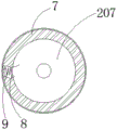
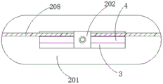
The stirring mechanism 2 comprises a supporting plate 201, a sliding table 202, a bearing 203, a first motor 204, a rotating shaft 205, a stirring blade 206, a buffer disc 207 and a screw rod 208, the supporting plate 201 is fixedly connected on the inner wall of the stirring tank 1, the top of the supporting plate 201 is provided with a sliding groove 3, the bottom of the inner cavity of the sliding groove 3 is provided with a through hole 4, the sliding table 202 is movably connected inside the sliding groove 3, the screw rod 208 is in threaded connection with the sliding table 202, and is positioned above the supporting plate 201, the first motor 204 is fixedly connected with the top of the sliding table 202, and the output end of the first motor 204 passes through the bearing 203 and extends to the lower part of the sliding table 202, the rotating shaft 205 is connected with the output end of the first motor 204, and extend to the lower part of the supporting plate 201 through the through hole 4, the stirring blades 206 are fixedly connected to the outer side of the rotating shaft 205, and the buffer discs 207 are also fixedly connected to the outer side of the rotating shaft 205, and are provided with two groups which are symmetrically arranged above and below the stirring blades 206.
Wherein, one side fixedly connected with brace table 5 of agitator tank 1, second motor 6 is installed at the top of brace table 5, and the output of second motor 6 extends to the inner chamber of agitator tank 1 to with the one end fixed connection of lead screw 208.
Wherein, cushion collar 7 has been cup jointed to the periphery of cushion collar 207, cushion collar 7 is hollow structure, the outside fixedly connected with piston 8 of cushion collar 207, and the piston is located the inner chamber of cushion collar 7, the bottom fixedly connected with spring 9 of cushion collar 7 inner chamber, and the other end and the piston 8 fixed connection of spring 9, still fixedly connected with spliced pole 10 between the cushion collar 207, one side fixedly connected with scraper blade 11 that spliced pole 10 is close to agitator tank 1 inner wall, one side that cushion collar 7 is close to agitator tank 1 inner wall also is provided with scraper blade 11.
Wherein, the bottom of the buffer tray 207 below the stirring blade 206 is also fixedly connected with a cleaning tray 12 through a connecting rod, and the bottom of the cleaning tray 12 is fixedly connected with a scraper 11, so that the bottom of the stirring tank 1 can be cleaned.
Wherein, the spliced pole 10 is equipped with two, and the symmetry sets up in stirring vane 206's both sides, sets up the multiunit, is favorable to improving clean efficiency and quality.
Wherein, sealed lid is all installed to feed inlet 101 and discharge gate 102, and filter 13 is still installed to the inside of gas vent 103, can prevent that the irritative gas that produces in the coating production process from not having the processing to discharge, is harmful to human health.
The stirring tank 1 is formed by splicing a rectangular tank body in the middle and semicircular tank bodies on two sides, and the sliding table 202 is positioned on the central line of the two semicircular tank bodies.
One specific application of this embodiment is: by adding raw ingredients and additives of the coating into the feed inlet 101, the first motor 204 is turned on by the control panel 104, the first motor 204 drives the stirring blade 206 to rotate, and acts on the coating in the stirring tank 1, meanwhile, the second motor 6 is turned on, the second motor 6 drives the screw rod 208 to rotate, so that the sliding table 202 moves above the chute 3 and drives the stirring blade 206 to move in the stirring tank 1, the coating in the whole tank can be stirred, the forward and reverse rotation of the second motor 6 is manually or regularly controlled by the control panel 104, so that the sliding table 202 reciprocates, the arranged buffer disc 207 can prevent the stirring blade 206 from colliding with the inner wall of the stirring tank 1 in the back and forth movement process, the moving speed of the sliding table 202 can be reduced, the stirring effect is improved, harmful gas generated during stirring is discharged after being filtered by the filter plate 13 in the exhaust port 103, and the coating is discharged through the discharge port 102 after stirring is completed, when cleaning is needed, clear water and detergent are injected through the feed inlet 101, the first motor 204 and the second motor 6 are opened through the control panel 104 again, as above, the sliding table 202 reciprocates to drive the connecting column 10 and the scraper 11 on the cleaning disc 12 to act on the inner wall and the bottom of the stirring tank 1, so that the cleaning effect is better.
In the description herein, references to the description of "one embodiment," "an example," "a specific example," etc., mean that a particular feature, structure, material, or characteristic described in connection with the embodiment or example is included in at least one embodiment or example of the invention. In this specification, the schematic representations of the terms used above do not necessarily refer to the same embodiment or example. Furthermore, the particular features, structures, materials, or characteristics described may be combined in any suitable manner in any one or more embodiments or examples.
The preferred embodiments of the present invention disclosed above are intended only to help illustrate the present invention. The preferred embodiments are not intended to be exhaustive or to limit the invention to the precise embodiments disclosed. Obviously, many modifications and variations are possible in light of the above teaching. The embodiments were chosen and described in order to best explain the principles of the invention and its practical applications, to thereby enable others skilled in the art to best understand the invention for and utilize the invention. The present invention is limited only by the claims and their full scope and equivalents.
Claims (7)
1. A stirring and mixing device for paint production is characterized in that; the stirring device comprises a stirring tank (1) and a stirring mechanism (2), wherein the stirring mechanism (2) is arranged inside the stirring tank (1), the stirring tank (1) comprises a feeding hole (101), a discharging hole (102), an exhaust port (103) and a control panel (104), the feeding hole (101) is arranged above the left side of the stirring tank (1), the discharging hole (102) is arranged below the right side of the stirring tank (1), the exhaust port (103) is arranged at the top of the stirring tank (1), and the control panel (104) is arranged at one end, far away from the exhaust port (103), of the top of the stirring tank (1);
the stirring mechanism (2) comprises a supporting plate (201), a sliding table (202), a bearing (203), a first motor (204), a rotating shaft (205), a stirring blade (206), a buffer disc (207) and a screw rod (208), wherein the supporting plate (201) is fixedly connected to the inner wall of the stirring tank (1), a sliding groove (3) is formed in the top of the supporting plate (201), a through hole (4) is formed in the bottom of the inner cavity of the sliding groove (3), the sliding table (202) is movably connected to the inside of the sliding groove (3), the screw rod (208) is in threaded connection with the sliding table (202) and is positioned above the supporting plate (201), the first motor (204) is fixedly connected to the top of the sliding table (202), the output end of the first motor (204) penetrates through the bearing (203) and extends to the lower portion of the sliding table (202), and the rotating shaft (205) is connected to the output end of the first, and extend to the below of backup pad (201) through-hole (4), stirring vane (206) fixed connection is in the outside of pivot (205), buffer disc (207) also fixed connection is in the outside of pivot (205), and is equipped with two sets ofly, and the symmetry is installed in the upper and lower below of stirring vane (206).
2. The stirring and mixing device for paint production as claimed in claim 1, wherein: one side fixedly connected with brace table (5) of agitator tank (1), second motor (6) are installed at the top of brace table (5), and the output of second motor (6) extends to the inner chamber of agitator tank (1) to with the one end fixed connection of lead screw (208).
3. The stirring and mixing device for paint production as claimed in claim 1, wherein: buffer sleeve (7) have been cup jointed to the periphery of buffer disc (207), and buffer sleeve (7) are hollow structure, outside fixedly connected with piston (8) of buffer disc (207), and the piston is located the inner chamber of buffer sleeve (7), bottom fixedly connected with spring (9) of buffer sleeve (7) inner chamber, and the other end and piston (8) fixed connection of spring (9), still fixedly connected with spliced pole (10) between buffer disc (207), one side fixedly connected with scraper blade (11) that spliced pole (10) are close to agitator tank (1) inner wall, one side that buffer sleeve (7) are close to agitator tank (1) inner wall also is provided with scraper blade (11).
4. The stirring and mixing device for paint production as claimed in claim 1, wherein: the bottom of the buffer disc (207) below the stirring blade (206) is also fixedly connected with a cleaning disc (12) through a connecting rod, and the bottom of the cleaning disc (12) is fixedly connected with a scraping plate (11).
5. The stirring and mixing device for paint production as claimed in claim 3, wherein: the two connecting columns (10) are symmetrically arranged on two sides of the stirring blade (206).
6. The stirring and mixing device for paint production as claimed in claim 3, wherein: sealed lid is all installed to feed inlet (101) and discharge gate (102), filter (13) are still installed to the inside of gas vent (103).
7. The stirring and mixing device for paint production according to claim 1, wherein; the stirring tank (1) is formed by splicing a rectangular tank body in the middle and semicircular tank bodies on two sides, and the sliding table (202) is positioned on the central line of the two semicircular tank bodies.
Priority Applications (1)
| Application Number | Priority Date | Filing Date | Title |
|---|---|---|---|
| CN201920951860.1U CN210206529U (en) | 2019-06-24 | 2019-06-24 | Stirring and mixing device for paint production |
Applications Claiming Priority (1)
| Application Number | Priority Date | Filing Date | Title |
|---|---|---|---|
| CN201920951860.1U CN210206529U (en) | 2019-06-24 | 2019-06-24 | Stirring and mixing device for paint production |
Publications (1)
| Publication Number | Publication Date |
|---|---|
| CN210206529U true CN210206529U (en) | 2020-03-31 |
Family
ID=69933455
Family Applications (1)
| Application Number | Title | Priority Date | Filing Date |
|---|---|---|---|
| CN201920951860.1U Active CN210206529U (en) | 2019-06-24 | 2019-06-24 | Stirring and mixing device for paint production |
Country Status (1)
| Country | Link |
|---|---|
| CN (1) | CN210206529U (en) |
Cited By (1)
| Publication number | Priority date | Publication date | Assignee | Title |
|---|---|---|---|---|
| CN111745815A (en) * | 2020-07-01 | 2020-10-09 | 冯易 | Mortar preparation facilities convenient to it is clean |
-
2019
- 2019-06-24 CN CN201920951860.1U patent/CN210206529U/en active Active
Cited By (2)
| Publication number | Priority date | Publication date | Assignee | Title |
|---|---|---|---|---|
| CN111745815A (en) * | 2020-07-01 | 2020-10-09 | 冯易 | Mortar preparation facilities convenient to it is clean |
| CN111745815B (en) * | 2020-07-01 | 2021-08-13 | 山东绿屋墙体保温科技有限公司 | Mortar preparation facilities convenient to it is clean |
Similar Documents
| Publication | Publication Date | Title |
|---|---|---|
| CN210206529U (en) | Stirring and mixing device for paint production | |
| CN209155683U (en) | A kind of automatically cleaning blender | |
| CN208482337U (en) | A kind of water-repellent paint agitating device | |
| CN211944727U (en) | Coating storage device | |
| CN211562619U (en) | Artificial plastic edible oil emulsifying tank convenient to clean | |
| CN210097474U (en) | Coating stirrer with scraper | |
| CN209885662U (en) | Make things convenient for coating stirrer of ejection of compact | |
| CN220110847U (en) | Paint diluting equipment | |
| CN209631066U (en) | Food processing field batch mixer | |
| CN218928201U (en) | Low-speed stirring device convenient to clean | |
| CN213611175U (en) | Quick stirring pot for cosmetics | |
| CN210097447U (en) | Coating stirrer convenient to clean | |
| CN211274347U (en) | Stirring tank | |
| CN111888983A (en) | Mixed liquid stirring device for chemical production | |
| CN216024481U (en) | Herbal paste blending and mixing tank | |
| CN220715564U (en) | Cleanable raw material stirring mechanism | |
| CN111111511A (en) | Bio-based coating agitating unit based on gear drive principle | |
| CN216726695U (en) | High-efficient emulsification device is used in cosmetics production | |
| CN219984471U (en) | Stirring device of high-speed stirrer | |
| CN220294471U (en) | Stirring tank for high-viscosity materials | |
| CN215782976U (en) | Stirring mixer for granular materials | |
| CN219463708U (en) | Automatic chemical feeding device for flotation | |
| CN219376816U (en) | Paste preparation device convenient to clean | |
| CN215463828U (en) | Sealed production of gluing of silicone is with compounding processingequipment | |
| CN220737240U (en) | Reclaimed rubber mixing device capable of preventing inner wall from sticking |
Legal Events
| Date | Code | Title | Description |
|---|---|---|---|
| GR01 | Patent grant | ||
| GR01 | Patent grant |