CN210182700U - Metering box secondary wiring misconnection prevention device - Google Patents
Metering box secondary wiring misconnection prevention device Download PDFInfo
- Publication number
- CN210182700U CN210182700U CN201921042047.9U CN201921042047U CN210182700U CN 210182700 U CN210182700 U CN 210182700U CN 201921042047 U CN201921042047 U CN 201921042047U CN 210182700 U CN210182700 U CN 210182700U
- Authority
- CN
- China
- Prior art keywords
- shell
- jack
- elastic contact
- connecting mechanism
- secondary wiring
- Prior art date
- Legal status (The legal status is an assumption and is not a legal conclusion. Google has not performed a legal analysis and makes no representation as to the accuracy of the status listed.)
- Expired - Fee Related
Links
Images


Landscapes
- Details Of Connecting Devices For Male And Female Coupling (AREA)
Abstract
The utility model discloses a metering box secondary wiring mistake proofing connects device, include: the device comprises a first connecting mechanism and a second connecting mechanism, wherein the first connecting mechanism is provided with a first shell, a jack and an elastic contact piece, and the second connecting mechanism is provided with a second shell and a conductive column; the jack is seted up in first shell one side, and elastic contact installs inside first shell, and elastic contact sets up in the jack both sides, leads electrical pillar and connects in a second shell side, and it is fixed with elastic contact to lead electrical pillar, the utility model discloses because the grouping of leading electrical pillar and jack is one of them group number three, and another group number is four, consequently only has a connected mode when the elastic contact who will lead electrical pillar and jack inside is connected, can effectively avoid appearing the condition of connecing the electric current line and voltage line wrong like this, has saved the time that the staff discerned the cable, has improved work efficiency and the degree of accuracy of working a telephone switchboard.
Description
Technical Field
The utility model relates to a power equipment technical field specifically is a metering box secondary wiring mistake proofing connects device.
Background
At present all 10kV high voltage combination batch meters all install on various outdoor transformer platform circuit breaker upper ends or branch circuit pole rack, the position of installation is higher for ground, consequently all treat when actual installation that all installation projects finish through installing the table again and connect the electricity work after checking and accepting, and the inside cable of batch meter is seven core cables, because the sinle silk need insert electric current and voltage transformer respectively, consequently seven sinle silks include three ampere wires and four voltage lines, when installing the table and connect the electricity, need the people to climb up the pole and go to distinguish mutually other and electric current, the voltage wiring.
However, the existing current and voltage secondary cables do not have marks and colors for distinguishing, and cannot be distinguished by using the sections of the current and voltage cables, and meanwhile, workers also need to perform pole climbing operation, so that the safety risk in installation work is increased, the labor intensity is high, the consumed time is long, the installation efficiency is low, and the power failure time is long; especially, the service skill levels of the metering personnel of the power supply enterprises at all levels are uneven, various wiring errors are easily caused, once the wiring errors occur, the electric quantity is not counted or counted, and great loss is caused
SUMMERY OF THE UTILITY MODEL
An object of the utility model is to provide a batch meter secondary wiring mistake proofing connects device to solve the problem that proposes in the above-mentioned background art.
In order to achieve the above object, the utility model provides a following technical scheme: the utility model provides a batch meter secondary wiring mistake proofing connects device, includes: the device comprises a first connecting mechanism and a second connecting mechanism, wherein the first connecting mechanism is provided with a first shell, a jack and an elastic contact piece, and the second connecting mechanism is provided with a second shell and a conductive column;
the jack is opened in first shell one side, elastic contact installs inside the first shell, elastic contact sets up the jack both sides, it connects to lead electrical pillar second shell side, it can by to lead electrical pillar after passing the jack elastic contact presss from both sides tightly fixedly.
Further, the method also comprises the following steps: first threading pipe and second threading pipe, first threading pipe through connection be in first shell is kept away from jack side, second threading pipe through connection be in the second shell is kept away from lead electrical pillar side.
Furthermore, an elbow is arranged at one end, away from the first shell, of the first threading pipe, and an included angle between the elbow and the first threading pipe is forty-five degrees.
Further, the method also comprises the following steps: and the installation fixing plate is fixedly welded with the edge of the side face of the outer wall of the first shell, and the installation fixing plate is arranged on the adjacent side face of the jack where the first shell is located.
Further, the method also comprises the following steps: and the connecting and fixing plate is fixedly welded at the side edge of the outer wall of the first shell and the second shell respectively and is used for fixing the first shell and the second shell.
Further, the method also comprises the following steps: the groove is formed in the first shell and located on one side face where the jack is located, the jack is formed in the groove, the boss is arranged on the second shell and located on one side face where the conductive column is located, and the conductive column is arranged on the surface of the boss.
Compared with the prior art, the beneficial effects of the utility model are that:
because the grouping of leading electrical pillar and jack is one of them group's number for three, another group's number is four, consequently only there is a connected mode when connecting leading electrical pillar and the inside elastic contact piece of jack, promptly set up the same a set of interconnect of number promptly, when being connected leading electrical pillar and jack that set up the number difference, can be because the position corresponds and lead to unable the connection, can effectively avoid appearing the condition that connects the electric current line with the voltage line mistake like this, saved the time that the staff discerned the cable, improved work efficiency and wiring degree of accuracy.
Drawings
Fig. 1 is a schematic view of a three-dimensional structure of a secondary wiring misconnection prevention device of a metering box in an embodiment of the present invention;
FIG. 2 is a schematic perspective view of a first connecting mechanism of the secondary wiring mis-connection preventing device of the metering box in the embodiment of FIG. 1;
FIG. 3 is a schematic perspective view of a second connecting mechanism of the secondary wiring mis-connection preventing device of the metering box in the embodiment of FIG. 1;
fig. 4 is a schematic perspective view of the elastic contact piece and the conductive column of the secondary wiring anti-misconnecting device of the metering box in the embodiment of fig. 1.
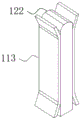
In FIGS. 1-4: 11-a first connection mechanism; 111-a first housing; 112-a jack; 113-elastic contact piece; 12-a second connection mechanism; 121-a second housing; 122-conductive pillars; 131-a first threading tube; 132-a second threading tube; 14-mounting a fixing plate; 15-connecting the fixing plate; 161-grooves; 162-boss.
Detailed Description
The technical solutions in the embodiments of the present invention will be described clearly and completely with reference to the accompanying drawings in the embodiments of the present invention, and it is obvious that the described embodiments are only some embodiments of the present invention, not all embodiments. Based on the embodiments in the present invention, all other embodiments obtained by a person skilled in the art without creative work belong to the protection scope of the present invention.
Referring to fig. 1-4, fig. 1 is a schematic diagram of a three-dimensional structure of a secondary wiring misconnection prevention device of a metering box according to an embodiment of the present invention; FIG. 2 is a schematic perspective view of a first connecting mechanism of the secondary wiring mis-connection preventing device of the metering box in the embodiment of FIG. 1; FIG. 3 is a schematic perspective view of a second connecting mechanism of the secondary wiring mis-connection preventing device of the metering box in the embodiment of FIG. 1; fig. 4 is a schematic perspective view of the elastic contact piece and the conductive column of the secondary wiring anti-misconnecting device of the metering box in the embodiment of fig. 1.
The utility model provides a technical scheme: the utility model provides a batch meter secondary wiring mistake proofing connects device, includes: a first connecting mechanism 11 and a second connecting mechanism 12, wherein the first connecting mechanism 11 comprises a first housing 111, a jack 112 and a resilient contact piece 113, and the second connecting mechanism 12 comprises a second housing 121 and a conductive column 122;
wherein, the first shell 111 and the second shell 121 are both a cubic shell structure, the jack 112 is opened on one of the six sides of the first shell 111, and the jack 112 is provided with seven jacks 112, the seven jacks 112 are divided into two groups, one group is three jacks 112, the elastic contact 113 arranged inside the jack is used for connecting current lines, the other group is four jacks 112, the elastic contact 113 arranged inside the jack is used for connecting voltage lines, each group is equidistantly arranged on the same straight line, meanwhile, the straight lines of the two groups of jacks 112 are mutually parallel, further, the elastic contact 113 is clamped and installed inside the first shell 111, and the elastic contact 113 is arranged at the two sides of the jack 112, the space size between the elastic contacts 113 arranged at the two sides of the same jack 112 is kept smaller than the thickness size of the conductive column 122, so that when the conductive column 122 is inserted into the jack 112, the elastic contacts 113 at the two sides inside the jack 112 can be pressed by the conductive column 122 to move outwards, let elastic contact 113 rely on elasticity to grasp conductive column 122 under the deformation state, guarantee that elastic contact 113 can fully contact with conductive column 122 to make elastic contact 113 and conductive column 122 possess electrically conductive ability, avoid contact failure's condition to appear.
Further, the conductive pillar 122 is fixedly inserted into one of the six lateral sides of the second housing 121, such that one end of the conductive pillar 122 is located inside the second housing 121, the other end of the conductive pillar is located outside the second housing 121, one end of the conductive pillar 122 located inside the second housing 121 is electrically connected to a cable of a user terminal, and one end of the conductive pillar 122 located outside the second housing 121 is used for being inserted into the jack 112, such that the conductive pillar 122 can be electrically connected to the elastic contact 113 inside the jack 112; wherein, the conductive posts 122 are provided with seven, the seven conductive posts 122 are divided into two groups, one group is three conductive posts 122 for connecting a current line, the other group is four conductive posts 122 for connecting a voltage line, each group is equidistantly arranged on the same straight line, and the straight lines of the two groups of conductive posts 122 are parallel to each other, so that the arrangement pitch and the number of the conductive posts 122 are exactly the same as the arrangement pitch and the number of the jacks 112, thereby ensuring that the conductive posts 122 can be matched with the jacks 112 for use, and because the conductive posts 122 and the jacks 112 are grouped into one group of three and the other group of four, when the conductive posts 122 and the elastic contact pieces 113 inside the jacks 112 are connected, only one connection mode is provided, namely, the group of the same number is connected, when the conductive posts 122 with different numbers are connected with the jacks 112, the connection cannot be performed due to the position mismatch, the condition that connects wrong with electric current line and voltage line can effectively be avoided like this to appear.
Preferably, the first threading pipe 131 is connected to a side surface of the first shell 111 far away from the jack 112, and the first threading pipe 131 is in through connection with the first shell 111, so that the cable can pass through the first threading pipe 131 and be electrically connected with the elastic contact sheet 113 inside the first shell 111, wherein an elbow is arranged at one end of the first threading pipe 131 far away from the first shell 111, and an included angle between the elbow and the first threading pipe 131 is forty-five degrees; the second threading tube 132 is connected to a side surface of the second housing 121 far away from the conductive post 122, and the second threading tube 132 is connected to the second housing 121 in a penetrating manner, so that the cable can pass through the second threading tube 132 and be electrically connected to the conductive post 122 inside the second housing 121.
Preferably, the mounting and fixing plate 14 is fixedly welded to the side edge of the outer wall of the first housing 111, the mounting and fixing plate 14 is disposed on the side of the first housing 111 adjacent to the side where the insertion hole 112 is located, since the insertion hole 112 and the first threading tube 131 are respectively provided on two mutually opposite sides of the first housing 111, the side on which the fixing plate 14 is mounted is any two of the four sides therebetween, in actual outdoor installation, the first threading pipe 131 is located at the top of the first casing 111, and then the installation fixing plates 14 are respectively welded on two vertical edges of the first casing 111 near the utility pole, and the mounting and fixing plate 14 is in the same plane, the user can fasten the first housing 111 to the utility pole through the screw holes on the surface of the mounting and fixing plate 14, and can also fix the first housing 111 to the utility pole through the screw holes on the surface of the mounting and fixing plate 14 by screws.
Preferably, the connection fixing plates 15 are respectively fixedly welded at the side edges of the outer walls of the first shell 111 and the second shell 121, when the outdoor installation is performed, the first threading pipe 131 is kept on the upper surface of the first shell 111, and meanwhile, the second threading pipe 132 is arranged on the lower surface of the second shell 121 after the outdoor installation is performed, then the connection fixing plates 15 are respectively welded on the edges of the bottoms of the outer walls of the two sides of the first shell 111 and the edges of the tops of the outer walls of the two sides of the second shell 121, so that when the first shell 111 and the second shell 121 are installed together, the connection fixing plates 15 on the first shell 111 and the second shell 121 can be mutually overlapped, the connection fixing plates 15 which are overlapped can be conveniently fixed by using bolts, and the first shell 111 and the second shell 121 are further fixed.
Preferably, the groove 161 is formed in a side surface of the first housing 111 where the jack 112 is located, the jack 112 is formed in the groove 161, wherein the side surface of the first housing 111 where the jack 112 is located is translated by 2mm to 5mm toward the inside of the first housing 111 to form the groove 161, and the plane position and the distance formed by the jack 112 are not changed, the boss 162 is formed in a side surface of the second housing 112 where the conductive post 122 is located, the conductive post 122 is formed on the surface of the boss 162, wherein the side surface of the second housing 112 where the conductive post 122 is located is translated toward the outside of the second housing 112 by the distance the same as the depth of the groove 161 to form the boss 162, and the plane position and the distance formed by the conductive post 122 are not changed; because the jack 112 sets up at first shell 111 lower surface during actual installation, the direction sets up down, and conductive pillar 122 sets up at second shell 112 upper surface, the direction sets up, the mode that sets up like this can avoid the rainwater to get into inside first shell 111 through jack 112, but because the rainwater flows to conductive pillar 122 along the gap between first shell 111 and the second shell 121 easily, still can cause the short circuit, consequently set first shell 111 bottom to recess 161, set second shell 121 top to boss 162, even the rainwater gets into the gap between first shell 111 and the second shell 121, because the rainwater receives the influence of gravity also can't upwards flow to boss 162 top by oneself, further avoided the rainwater to cause the possibility of conductive pillar 122 short circuit.
The working principle is as follows: when the cable connector is used, a cable at the end of the metering box passes through the first threading pipe 131 to be electrically connected with the elastic contact sheet 113 in the first shell 111, a cable at a user end passes through the second threading pipe 132 to be electrically connected with the conductive post 122 in the second shell 121, seven jacks 112 are arranged, the seven jacks 112 are divided into two groups, one group is three jacks 112, the elastic contact sheet 113 arranged in each jack is used for connecting a current line, the other group is four jacks 112, the elastic contact sheet 113 arranged in each jack is used for connecting a voltage line, each group is equidistantly arranged on the same straight line, and meanwhile, the elastic contact sheet 113 can be fully contacted with the conductive post 122, so that the elastic contact sheet 113 and the conductive post 122 have the conductive capability; wherein, the conductive posts 122 are provided with seven, the seven conductive posts 122 are divided into two groups, one group is three conductive posts 122 for connecting a current line, the other group is four conductive posts 122 for connecting a voltage line, each group is equidistantly arranged on the same straight line, and the straight lines of the two groups of conductive posts 122 are parallel to each other, so that the arrangement pitch and the number of the conductive posts 122 are exactly the same as the arrangement pitch and the number of the jacks 112, thereby ensuring that the conductive posts 122 can be matched with the jacks 112 for use, and because the conductive posts 122 and the jacks 112 are grouped into one group of three and the other group of four, when the conductive posts 122 and the elastic contact pieces 113 inside the jacks 112 are connected, only one connection mode is provided, namely, the group of the same number is connected, when the conductive posts 122 with different numbers are connected with the jacks 112, the connection cannot be performed due to the position mismatch, can effectively avoid connecing the wrong condition appearance with electric current line and voltage line like this, save the time that the staff discerned the cable, improve work efficiency and the wiring degree of accuracy.
It is noted that, herein, relational terms such as first and second, and the like may be used solely to distinguish one entity or action from another entity or action without necessarily requiring or implying any actual such relationship or order between such entities or actions. Also, the terms "comprises," "comprising," or any other variation thereof, are intended to cover a non-exclusive inclusion, such that a process, method, article, or apparatus that comprises a list of elements does not include only those elements but may include other elements not expressly listed or inherent to such process, method, article, or apparatus.
Although embodiments of the present invention have been shown and described, it will be appreciated by those skilled in the art that changes, modifications, substitutions and alterations can be made in these embodiments without departing from the principles and spirit of the invention, the scope of which is defined in the appended claims and their equivalents.
Claims (6)
1. The utility model provides a batch meter secondary wiring mistake proofing connects device which characterized in that includes: the device comprises a first connecting mechanism and a second connecting mechanism, wherein the first connecting mechanism is provided with a first shell, a jack and an elastic contact piece, and the second connecting mechanism is provided with a second shell and a conductive column;
the jack is opened in first shell one side, elastic contact installs inside the first shell, elastic contact sets up the jack both sides, it connects to lead electrical pillar second shell side, it can by to lead electrical pillar after passing the jack elastic contact presss from both sides tightly fixedly.
2. The metering box secondary wiring misconnection prevention device of claim 1, further comprising: first threading pipe and second threading pipe, first threading pipe through connection be in first shell is kept away from jack side, second threading pipe through connection be in the second shell is kept away from lead electrical pillar side.
3. The metering box secondary wiring misconnection prevention device of claim 2, wherein: an elbow is arranged at one end, away from the first shell, of the first threading pipe, and an included angle between the elbow and the first threading pipe is forty-five degrees.
4. The metering box secondary wiring misconnection prevention device of claim 1, further comprising: and the installation fixing plate is fixedly welded with the edge of the side face of the outer wall of the first shell, and the installation fixing plate is arranged on the adjacent side face of the jack where the first shell is located.
5. The metering box secondary wiring misconnection prevention device of claim 1, further comprising: and the connecting and fixing plate is fixedly welded at the side edge of the outer wall of the first shell and the second shell respectively and is used for fixing the first shell and the second shell.
6. The metering box secondary wiring misconnection prevention device of claim 1, further comprising: the groove is formed in the first shell and located on one side face where the jack is located, the jack is formed in the groove, the boss is arranged on the second shell and located on one side face where the conductive column is located, and the conductive column is arranged on the surface of the boss.
Priority Applications (1)
| Application Number | Priority Date | Filing Date | Title |
|---|---|---|---|
| CN201921042047.9U CN210182700U (en) | 2019-07-05 | 2019-07-05 | Metering box secondary wiring misconnection prevention device |
Applications Claiming Priority (1)
| Application Number | Priority Date | Filing Date | Title |
|---|---|---|---|
| CN201921042047.9U CN210182700U (en) | 2019-07-05 | 2019-07-05 | Metering box secondary wiring misconnection prevention device |
Publications (1)
| Publication Number | Publication Date |
|---|---|
| CN210182700U true CN210182700U (en) | 2020-03-24 |
Family
ID=69840176
Family Applications (1)
| Application Number | Title | Priority Date | Filing Date |
|---|---|---|---|
| CN201921042047.9U Expired - Fee Related CN210182700U (en) | 2019-07-05 | 2019-07-05 | Metering box secondary wiring misconnection prevention device |
Country Status (1)
| Country | Link |
|---|---|
| CN (1) | CN210182700U (en) |
-
2019
- 2019-07-05 CN CN201921042047.9U patent/CN210182700U/en not_active Expired - Fee Related
Similar Documents
| Publication | Publication Date | Title |
|---|---|---|
| CN201063044Y (en) | Direct type three-phase four-wire electric energy meter | |
| CN105548635A (en) | Electric energy meter connector assembly | |
| CN104849522A (en) | Three-phase plug-in type electric energy meter mounting seat and use method | |
| CN210182700U (en) | Metering box secondary wiring misconnection prevention device | |
| CN114236205A (en) | Electric energy meter base and corresponding method for replacing electric energy meter without power outage | |
| CN203310886U (en) | Ammeter concentrated metering box | |
| CN202455013U (en) | Closed intensive busbar bridge | |
| CN205353152U (en) | Electric energy meter plug connector | |
| CN205427000U (en) | Electric power metering device secondary side wiring integrated equipment | |
| CN204154772U (en) | City illumination energy effect system centralized detection table case | |
| CN204156252U (en) | A kind of PDU unit for network cabinet | |
| CN211579046U (en) | A protective cover for intelligent electric energy meter terminal row | |
| CN201063043Y (en) | Mutual inductance type three-phase four-wire electric energy meter | |
| CN210378035U (en) | Electrician and electronic wiring training device | |
| CN208939544U (en) | One kind can plug protector cross-connect grounding box | |
| CN205960294U (en) | Rail mounted supply socket | |
| CN220306615U (en) | PDU row who conveniently overhauls inserts structure | |
| CN212965043U (en) | AC/DC parameter tester | |
| CN215005495U (en) | Parallel connection using device of digital power meter | |
| CN210052859U (en) | Binding post of quick installation | |
| CN201540316U (en) | Improved structure of kilowatt-hour meter junction box | |
| CN211236216U (en) | Terminal box convenient to electric energy meter precision check-up | |
| CN203787590U (en) | Horizontally-assembled electric energy metering box wire connection terminal | |
| CN204614654U (en) | A kind of instant-plugging current transformer device | |
| CN213457134U (en) | Low current grounding line selection test bench |
Legal Events
| Date | Code | Title | Description |
|---|---|---|---|
| GR01 | Patent grant | ||
| GR01 | Patent grant | ||
| CF01 | Termination of patent right due to non-payment of annual fee | ||
| CF01 | Termination of patent right due to non-payment of annual fee |
Granted publication date: 20200324 Termination date: 20200705 |