CN210179389U - Cooling system and stage lamp with same - Google Patents
Cooling system and stage lamp with same Download PDFInfo
- Publication number
- CN210179389U CN210179389U CN201920998405.7U CN201920998405U CN210179389U CN 210179389 U CN210179389 U CN 210179389U CN 201920998405 U CN201920998405 U CN 201920998405U CN 210179389 U CN210179389 U CN 210179389U
- Authority
- CN
- China
- Prior art keywords
- cup
- fan
- plate
- light
- air guide
- Prior art date
- Legal status (The legal status is an assumption and is not a legal conclusion. Google has not performed a legal analysis and makes no representation as to the accuracy of the status listed.)
- Active
Links
Images


Abstract
The utility model discloses a cooling system and have cooling system's stage lamp, including the anti-light cup that is used for placing the luminous body, first fan, air guide mouth and fixed plate, anti-light cup first fan air guide mouth all sets up same one side of fixed plate, the fixed plate has the light trap, the anti-light cup cover is established on the light trap and with the fixed plate laminating, first breach and second breach have been seted up to anti-light cup's rim of a cup lateral wall, air guide mouth certainly first breach stretches into in the anti-light cup, the air current mouth of first fan with air guide mouth intercommunication. The reflecting cup, the first fan and the air guide nozzle are all arranged on the same side of the fixed plate, so that the space on the other side of the fixed plate is saved, more functional modules can be placed, and conditions are created for realizing the function diversification of the lamp.
Description
Technical Field
The utility model relates to a stage lamp technical field, more specifically relates to a cooling system and have cooling system's stage lamp.
Background
Generally, a reflecting cup is arranged in the stage lighting equipment to collect light emitted by a light source, and the light source can generate a large amount of heat, so that the heat dissipation of the light source part of the lamp is very important, and the service life of a bulb and the service life of the lamp are directly related.
The general cover of stage lamp's reflection of light cup is established on a side surface of fixed plate, the cup along with the fixed plate laminating, the fixed plate corresponds reflection of light cup's rim of a cup sets up the light trap, then the opposite side of fixed plate sets up the wind-guiding mouth, because in order to save space, the fan can set up with reflection of light cup the fixed plate is with one side, the utilization is passed the ventilation passageway of fixed plate with the wind-guiding mouth is connected to introduce the cold air flow in the reflection of light cup. At present, the structure of the stage lamp is more and more compact, especially, between a fixed plate and a focus of a reflecting cup, more and more elements are needed to be arranged, but the air guide nozzle can occupy a certain space, and the compactness of the stage lamp is influenced.
SUMMERY OF THE UTILITY MODEL
An object of the utility model is to overcome at least one kind defect among the above-mentioned prior art, provide a cooling system, when guaranteeing the radiating effect, reduced the space that occupies.
In order to solve the technical problem, the utility model discloses a technical scheme is: the utility model provides a heat dissipation system, is including the reflection of light cup that is used for placing the luminous body, first fan, air guide nozzle and fixed plate, reflection of light cup first fan the air guide nozzle all sets up same one side of fixed plate, the fixed plate has the light trap, reflection of light cup cover establish on the light trap and with the fixed plate laminating, first breach and second breach have been seted up to reflection of light cup's rim of a cup lateral wall, air guide nozzle certainly first breach stretches into in the reflection of light cup, the air current mouth of first fan with air guide nozzle intercommunication.
The cooling system the rim of a cup lateral wall of anti-light cup directly reserves first breach with the second breach, one side of wind guiding nozzle with the air current mouth intercommunication of first fan, the opposite side passes through first breach stretches into in the anti-light cup, guide the cold air current to in the anti-light cup, it is right the luminous body dispels the heat, and the hot gas flow is followed the second breach flows, to different shapes anti-light cup through designing not equidimension and angle the wind guiding nozzle is right the luminous body carries out high-efficient even heat dissipation. Meanwhile, the reflecting cup, the first fan and the air guide nozzle are arranged on the same side of the fixing plate, so that the space on the other side of the fixing plate is saved, more functional modules can be placed, and conditions are created for realizing the function diversification of the lamp.
Furthermore, the first notch and the second notch are oppositely arranged, the first notch is used as a cold air inlet, the second notch is used as a heat exhaust airflow, or the first notch is used as a heat exhaust airflow, and the second notch is used as a cold air inlet, so that hot air in the reflection cup can be discharged more timely and efficiently.
Furthermore, the number of the first fan and the number of the air guide nozzles are at least 2, the first fan is respectively communicated with one air guide nozzle, and the air outlet directions of the air guide nozzles respectively face to two sides of the luminous body. First fan sets up different wind speeds according to the inclination of stage lamp, is directed at the higher one side of luminous body temperature is cooled down, makes the heat dissipation nimble more high-efficient.
Furthermore, a plurality of the air guide nozzles are connected into a whole, so that the space is saved, and the installation is easy.
Furthermore, the air guide nozzle comprises a first side plate and a second side plate which are arranged oppositely, the first side plate is close to the fixed plate and is parallel to the fixed plate, one end, close to the reflection cup, of the second side plate inclines towards the direction of the fixed plate, so that the air guide nozzle is matched with the first notch, and under the condition that the depth of the first notch is shallow, the air guide nozzle is completely arranged below the fixed plate.
Furthermore, one end of the first side plate, which is close to the reflection cup, is connected with a first extension plate, the tail end of the first extension plate inclines towards the bottom of the reflection cup, and one end of the second side plate, which is close to the reflection cup, is connected with a second extension plate which is opposite to the first extension plate. The cold air flow guided out from the air guide nozzle can be partially blown to the light-emitting position of the light-emitting body directly, so that the temperature of the light-emitting body is reduced more rapidly and efficiently, the light-emitting body is maintained within a certain temperature range, and the light-emitting body can exert the optical performance and ensure the service life at the same time.
Furthermore, the light-reflecting cup also comprises a heat insulation sheet for sealing the light-transmitting hole, and a closed space which is only provided with the first gap and the second gap is formed by the heat insulation sheet, the fixing plate and the light-reflecting cup.
Furthermore, the wind guide device also comprises a coaming covered on the fixed plate, the coaming is provided with an accommodating cavity, the reflection cup is positioned in the accommodating cavity, and an enclosed space is enclosed by the reflection cup, a bottom plate positioned at the bottom of the coaming and the wind guide nozzle
Furthermore, a second fan is arranged on the outer side of the enclosing plate, and an air outlet of the second fan is aligned to the bottom of the reflecting cup. The bottom of the reflecting cup is cooled, and hot air discharged from the reflecting cup to the accommodating cavity is accelerated to be blown out of the lamp body in time.
Further, the bottom plate is provided with an exhaust port, and a light blocking device is arranged at the exhaust port. The hot air in the containing cavity is guided out of the lamp while light leakage is prevented, the temperature in the containing cavity is ensured to be uniform, and local overheating is avoided. Meanwhile, the bottom plate is integrally detachable, and maintenance and installation are facilitated.
The utility model also provides a stage lamp, including any of the aforesaid cooling system places more function modules for stage lamp and saves sufficient space.
Drawings
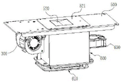
Fig. 1 is a schematic view of an overall structure of a heat dissipation system according to an embodiment of the present invention.
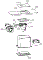
Fig. 2 is an exploded view of the overall structure of the heat dissipation system according to the embodiment of the present invention.
Fig. 3 is a schematic top view of the heat dissipation system according to the embodiment of the present invention.
Fig. 4 is a sectional view taken along a-a in fig. 3.
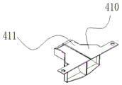
Fig. 5 is a schematic view of an overall structure of a wind guiding nozzle of the heat dissipation system according to the embodiment of the present invention.
Fig. 6 is a side view of a tuyere of a heat dissipation system according to an embodiment of the present invention.
100. A light emitter; 200. a light reflecting cup; 210. a first notch; 220. a second notch; 230. positioning a plate; 300. a first fan; 400. a wind guide nozzle; 410. a first side plate; 411. a first extension plate; 420. a second side plate; 421. a second extension plate; 500. a fixing plate; 510. a light-transmitting hole; 520. a heat insulating sheet; 521. a heat insulating sheet holder; 600. enclosing plates; 610. a base plate; 620. an accommodating cavity; 630. a second fan; 611. an exhaust port; 612. a light blocking device.
Detailed Description
The drawings of the present invention are for illustration purposes only and are not to be construed as limiting the invention. For the purpose of better illustrating the embodiments, certain features of the drawings may be omitted, enlarged or reduced, and do not represent the size of an actual product; it will be understood by those skilled in the art that certain well-known structures in the drawings and descriptions thereof may be omitted. The positional relationships depicted in the drawings are for illustrative purposes only and are not to be construed as limiting the present patent.
As shown in fig. 1 to 4, a heat dissipation system includes a reflective cup 200 for placing a light emitter 100, a first fan 300, a wind guiding nozzle 400 and a fixing plate 500, wherein the reflective cup 200, the first fan 300 and the wind guiding nozzle 400 are all disposed on the same side of the fixing plate 500, the fixing plate 500 has a light transmitting hole 510, the reflective cup 200 is covered on the light transmitting hole 510 and attached to the fixing plate 500, a first notch 210 and a second notch 220 are disposed on a cup rim side wall of the reflective cup 200, the wind guiding nozzle 400 extends into the reflective cup 200 from the first notch 210, and an airflow port of the first fan 300 is communicated with the wind guiding nozzle 400.
In the above heat dissipation system, the first notch 210 and the second notch 220 are directly reserved on the sidewall of the cup opening of the reflective cup 200, one side of the air guide nozzle 400 is communicated with the airflow port of the first fan 300, and the other side of the air guide nozzle extends into the reflective cup 200 through the first notch 210, so as to guide the cold airflow into the reflective cup 200, so as to dissipate the heat of the illuminant 100, and the hot airflow flows out from the second notch 220, so that the air guide nozzles 400 with different sizes and angles are designed for the reflective cups 100 with different shapes, so as to efficiently and uniformly dissipate the heat of the illuminant 100. Meanwhile, the reflecting cup 100, the first fan 300 and the air guide nozzle 400 are all arranged on the same side of the fixing plate 500, so that the space on the other side of the fixing plate 500 is saved, more functional modules can be placed conveniently, and conditions are created for realizing the function diversification of the lamp.
In other embodiments, the air guide nozzle 400 may be replaced by a duct, one end of which is communicated with the first fan 300, and the other end of which extends into the reflective cup 200 through the first notch 210, so as to guide the cold airflow generated by the first fan 300 into the reflective cup 200.
Optionally, the first notch 210 may also be used as a heat exhausting air flow port, and the first fan 300 is a suction fan.
In other embodiments, the first notch 210 and the second notch 220 may be respectively provided with the air guide nozzle 400 and the first fan 300, the first notch 210 blows cold air into the reflective cup 200, the second notch 220 draws hot air circulated by the reflective cup 200 out of the reflective cup 200, and at this time, the first fan 300 located in the second notch 220 is an exhaust fan.
In the preferred embodiment of the present invention, the first notch 210 and the second notch 220 are disposed oppositely, the first notch 210 is used as a cold air inlet, and the second notch 220 is used as a heat air outlet, which is beneficial to discharging the hot air in the reflective cup 200 more efficiently and timely.
In other embodiments, the first notch 210 can be used as a heat exhaust airflow port, and the second notch 220 can be used as a cooling airflow port.
In the preferred embodiment of the present invention, the number of the first fan 300 and the air guide nozzles 400 is at least 2, and a plurality of air guide nozzles 400 are connected as a whole, which is convenient for installation; the first fans 300 are respectively communicated with one air guide nozzle 400, the air outlet directions of the air guide nozzles 400 respectively face to two sides of the luminous body 100, hot air of the first fans 300 is guided into the reflective cup 200, the luminous body 100 is cooled and controlled in temperature, and aiming at the reflective cups 200 with different shapes, air inlets of the air guide nozzles 400 with different sizes and angles are designed to independently control the air speed and the air direction, so that the optimal heat dissipation effect is achieved.
In other embodiments, a plurality of the air guide nozzles 400 may be independently installed side by side.
Because stage lamp can carry out level and vertical direction's rotation according to stage effect's needs in the use, luminous body 100 also rotates thereupon, and the hot gas flow upward movement all the time under conventional stage lamp service environment leads to luminous body 100's heat concentration point position changes, sets up a plurality of first fan 300 can be according to the change of heat concentration point position and do the adjustment of adaptability, makes cooling system nimble more high-efficient.
In the preferred embodiment of the present invention, as shown in fig. 5 and 6, the wind guiding nozzle 400 includes a first side plate 410 and a second side plate 420 which are oppositely disposed, the first side plate 410 is close to the fixing plate 500 and parallel to the fixing plate 500, one end of the second side plate 420 close to the reflective cup 200 is inclined toward the fixing plate 500, the inclined angle of the second side plate 420 is designed according to the first notch 210, the end of the second side plate 420 and the bottom of the first notch 210 are at the same horizontal plane, so as to ensure that the wind guiding nozzle 400 is completely disposed under the fixing plate 500 under the condition that the depth of the first notch 210 is shallow.
In the preferred embodiment of the present invention, as shown in fig. 5 and 6, the first side plate 410 is close to one end of the reflective cup 200 and is connected with a first extension plate 411, the end of the first extension plate 411 is inclined toward the bottom of the reflective cup 200, and the second side plate 420 is close to one end of the reflective cup 200 and is connected with a second extension plate 421 opposite to the first extension plate 411. The cold air flow guided out from the air guide nozzle 400 can be partially blown to the light-emitting position of the light-emitting body 100, so that the temperature of the light-emitting body 100 can be reduced more rapidly and efficiently, the light-emitting body 100 can be maintained within a certain temperature range, and the light-emitting body 100 can exert the optical performance thereof and ensure the service life thereof.
In the preferred embodiment of the present invention, the light-transmitting hole 510 further comprises a heat insulation sheet 520 for sealing the light-transmitting hole 510, wherein the heat insulation sheet 520 is mounted on the fixing plate 500 through a heat insulation sheet frame 521, and the fixing plate 500 and the reflective cup 200 form a closed space with only the first gap 210 and the second gap 220. The cold air flow blown out by the air guide nozzle 400 enters the reflecting cup 200 through the air guide nozzle 400, and forms a vortex in the reflecting cup 200, so that the luminous body 100 is uniformly and efficiently cooled, and the requirement of the luminous body 100 on temperature is met.
In the preferred embodiment of the present invention, the reflective cup 200 is fixed on the fixing plate 500 by the positioning plate 230. More specifically, a mounting hole for fastening the rim of the reflective cup 200 is formed in the middle of the positioning plate 230. In the utility model discloses preferred embodiment, still establish including the cover bounding wall 600 on the fixed plate 500, the bounding wall 600 has and accepts the chamber 620, reflection of light cup 200 is located accept in the chamber 620, the bounding wall 600 encloses into airtight space with being located the bottom plate 610 of bounding wall 600 bottom equally, bottom plate 610 is provided with gas vent 611, gas vent 611 department is provided with the device 612 that is in the light of being in the light. The bottom plate 610 is integrally detachable, and maintenance and installation are facilitated. The hot air flow discharged from the reflecting cup 200 enters the containing cavity 620 and is discharged out of the lamp through the exhaust port 611 on the bottom plate 610, so that the high-temperature hot air flow is prevented from staying in the lamp. The light blocking device 612 located at the exhaust port 611 can prevent light from leaking out, and also can facilitate the hot air flow to be exhausted out of the lamp body.
In other embodiments, the bottom plate 610 may also be a part of the enclosure 600, and is integrated with the enclosure 600, and the air outlet 611 is provided, and the light blocking device 612 is provided at the air outlet 611.
In the preferred embodiment of the present invention, the second fan 630 is disposed outside the surrounding plate 600, the air outlet of the second fan 630 is aligned with the bottom of the reflective cup 200, which can be both right for cooling the bottom of the reflective cup 200, and at the same time, can also be accelerated from the reflective cup 200 to the outside of the hot air flow of the accommodating cavity 620 is blown out of the lamp body in time, so as to ensure that the temperature of the accommodating cavity 620 is uniform, and local overheating is avoided.
As shown in fig. 4, the working flow of the heat dissipation system is as follows: the cold air flow blown by the first fans 300 passes through the first notch 210 and enters a closed space formed by the first notch 210 and the second notch 220 and formed by the fixing plate 500, the reflective cup 200 and the air guide nozzles 400 from the plurality of air guide nozzles 400 communicated with the first notch 210, so as to cool and dissipate the heat of the luminous body 100, keep the temperature in the space uniform and control the temperature of the luminous body 100; the hot air flow exhausted from the enclosed space through the second notch 220 enters the receiving cavity 620 formed in the enclosure 600 and is exhausted out of the lamp through the exhaust port 611 of the bottom plate 610; the second fan 630 disposed on the enclosing plate 600 can cool the bottom of the reflective cup 200, and accelerate the hot air flow discharged from the reflective cup 200 to the accommodating cavity 620 to blow out the lamp body in time, so as to ensure uniform temperature of the accommodating cavity 620 and avoid local overheating. It should be noted that the plurality of first fans 300 are independently controlled by the control system, and the optimal ambient temperature required by the operation of the light emitting device 100 is achieved by controlling the wind speeds and the wind intake rates of the first fans under different working conditions, so as to ensure the normal life of the light source and the lamp.
The utility model also provides a stage lamp, including any of the aforesaid cooling system places more function modules for stage lamp and saves sufficient space.
It is obvious that the above embodiments of the present invention are only examples for clearly illustrating the present invention, and are not limitations to the embodiments of the present invention. Other variations and modifications will be apparent to persons skilled in the art in light of the above description. And are neither required nor exhaustive of all embodiments. Any modification, equivalent replacement, and improvement made within the spirit and principle of the present invention should be included in the protection scope of the claims of the present invention.
Claims (11)
1. The heat dissipation system is characterized by comprising a reflection cup (200) used for placing a luminous body (100), a first fan (300), a wind guide nozzle (400) and a fixing plate (500), wherein the reflection cup (200), the first fan (300) and the wind guide nozzle (400) are arranged on the same side of the fixing plate (500), the fixing plate (500) is provided with a light transmission hole (510), the reflection cup (200) is covered on the light transmission hole (510) and attached to the fixing plate (500), a first notch (210) and a second notch (220) are formed in the side wall of a cup opening of the reflection cup (200), the wind guide nozzle (400) extends into the reflection cup (200) from the first notch (210), and an airflow opening of the first fan (300) is communicated with the wind guide nozzle (400).
2. A heat dissipation system according to claim 1, wherein the first notch (210) is disposed opposite to the second notch (220).
3. The heat dissipation system of claim 1, wherein the number of the first fan (300) and the number of the air guide nozzles (400) are at least 2, the first fan (300) is respectively communicated with one air guide nozzle (400), and the air outlet directions of the air guide nozzles (400) are respectively towards two sides of the light body (100).
4. A heat dissipating system according to claim 3, wherein a plurality of the air guide nozzles (400) are connected as a single body.
5. The heat dissipation system of claim 1, wherein the air guide nozzle (400) comprises a first side plate (410) and a second side plate (420) which are oppositely arranged, the first side plate (410) is close to the fixing plate (500) and is parallel to the fixing plate (500), and one end of the second side plate (420) close to the reflective cup (200) is inclined towards the direction of the fixing plate (500).
6. A heat dissipation system as claimed in claim 5, wherein a first extension plate (411) is connected to the first side plate (410) near the reflective cup (200), a distal end of the first extension plate (411) is inclined toward a bottom of the reflective cup (200), and a second extension plate (421) opposite to the first extension plate (411) is connected to the second side plate (420) near the reflective cup (200).
7. The heat dissipating system of claim 1, further comprising a heat shield (520) sealing the light hole (510).
8. The heat dissipation system of claim 1, further comprising a shroud (600) covering the fixing plate (500), wherein the shroud (600) has a receiving cavity, and the reflector cup (200) is located in the receiving cavity.
9. The heat dissipation system of claim 8, wherein a second fan (630) is disposed outside the enclosure (600), and an air outlet of the second fan (630) is aligned with the bottom of the reflective cup (200).
10. The heat dissipation system of claim 8, further comprising a bottom plate (620) located at the bottom of the enclosure (600) and fastened to the enclosure (600), wherein the bottom plate (620) is provided with an air outlet (611), and a light blocking device (612) is disposed at the air outlet (611).
11. A stage lamp comprising the heat dissipation system of any one of claims 1 to 10.
Priority Applications (1)
| Application Number | Priority Date | Filing Date | Title |
|---|---|---|---|
| CN201920998405.7U CN210179389U (en) | 2019-06-29 | 2019-06-29 | Cooling system and stage lamp with same |
Applications Claiming Priority (1)
| Application Number | Priority Date | Filing Date | Title |
|---|---|---|---|
| CN201920998405.7U CN210179389U (en) | 2019-06-29 | 2019-06-29 | Cooling system and stage lamp with same |
Publications (1)
| Publication Number | Publication Date |
|---|---|
| CN210179389U true CN210179389U (en) | 2020-03-24 |
Family
ID=69839428
Family Applications (1)
| Application Number | Title | Priority Date | Filing Date |
|---|---|---|---|
| CN201920998405.7U Active CN210179389U (en) | 2019-06-29 | 2019-06-29 | Cooling system and stage lamp with same |
Country Status (1)
| Country | Link |
|---|---|
| CN (1) | CN210179389U (en) |
-
2019
- 2019-06-29 CN CN201920998405.7U patent/CN210179389U/en active Active
Similar Documents
| Publication | Publication Date | Title |
|---|---|---|
| TWI591419B (en) | Projector and electronic device | |
| TW201020462A (en) | Lighting module and lighting system | |
| KR101180457B1 (en) | Lighting apparatus and ventilation apparatus having the same | |
| US10837632B2 (en) | Spiral air guide device and stage light heat dissipation system provided with the spiral air guide device | |
| CN218914752U (en) | Multi-angle light lamp | |
| CN209932464U (en) | Baking oven | |
| CN111608546A (en) | Household electrical appliance | |
| CN210179389U (en) | Cooling system and stage lamp with same | |
| US11350799B2 (en) | Towel dryer | |
| CN100578349C (en) | Heat radiating device and projection machine heat radiation system | |
| CN115717699A (en) | Prevent LED light lighting device that generates heat | |
| CN201063253Y (en) | Cooling device and cooling system for projector | |
| CN212204210U (en) | Follow spot lamp with heat abstractor | |
| JPH11241826A (en) | High frequency heater | |
| CN101963746B (en) | Light source module and projector | |
| CN215489266U (en) | Light source cooling system and stage lamp with same | |
| CN217109282U (en) | Stage lamp easy to radiate heat | |
| CN217423183U (en) | Light source module and lamp | |
| CN216113942U (en) | LED lamp with heat radiation structure | |
| CN213362390U (en) | Stage lamp holder and stage lamp | |
| CN220367516U (en) | Projection equipment | |
| CN214790680U (en) | Medical cold light source for endoscope image system | |
| CN212481212U (en) | Heat dissipation device for moving head lamp | |
| CN217279243U (en) | Totally closed projector heat radiation structure | |
| KR100347100B1 (en) | Machining room cooling device for ventilation hooded microwave oven |
Legal Events
| Date | Code | Title | Description |
|---|---|---|---|
| GR01 | Patent grant | ||
| GR01 | Patent grant |