CN210170921U - Biogas residue and biogas slurry separator - Google Patents
Biogas residue and biogas slurry separator Download PDFInfo
- Publication number
- CN210170921U CN210170921U CN201920928702.4U CN201920928702U CN210170921U CN 210170921 U CN210170921 U CN 210170921U CN 201920928702 U CN201920928702 U CN 201920928702U CN 210170921 U CN210170921 U CN 210170921U
- Authority
- CN
- China
- Prior art keywords
- groups
- sets
- top end
- group
- working box
- Prior art date
- Legal status (The legal status is an assumption and is not a legal conclusion. Google has not performed a legal analysis and makes no representation as to the accuracy of the status listed.)
- Active
Links
Images


Abstract
The utility model relates to the technical field of auxiliary devices for separating biogas residues and biogas slurry, in particular to a biogas residue and biogas slurry separator; the filter plate comprises a filter plate and a working box, wherein a working chamber is arranged in the working box, the top end of the working box is communicated with a feeding hole, a feeding block is arranged at the feeding hole in a sealing and threaded manner, a maintenance hole is communicated with the rear side of the working box, a T-shaped maintenance block is arranged at the maintenance hole in a sealing and threaded manner, a conveying pipe is communicated with the lower part of the right side of the working box, and a conveying pump is communicated with the conveying pipe in a sealing manner; the filter plate is characterized by further comprising two groups of fixing blocks, two groups of clamp springs and two groups of limiting blocks, wherein limiting grooves are formed in the inner sides of the two groups of fixing blocks, a bearing seat is arranged in the middle of the bottom end of the filter plate, a ball bearing is rotatably fixed in the bearing seat, the filter plate further comprises a plurality of groups of rubber dredging rods, a rotating handle, a connecting frame and a rotating shaft, and further comprises a plurality of groups of first sleeve springs and a plurality of groups of first telescopic pipes, and further comprises a push plate, a push.
Description
Technical Field
The utility model relates to a technical field of natural pond sediment natural pond liquid separation auxiliary device especially relates to a natural pond sediment natural pond liquid separating centrifuge.
Background
As is well known, a biogas residue and biogas slurry separator is an auxiliary device which is used for roughly filtering and separating biogas residue and biogas slurry by a grid in the process of treating biogas waste liquid so as to better perform subsequent dry-wet separation, and is widely used in the field of separation of biogas residue and biogas slurry; the existing biogas residue and biogas slurry separator comprises a filter plate and a working box, wherein a working chamber is arranged in the working box, the top end of the working box is communicated with a feed inlet, a feed blocking block is arranged at the seal screw at the feed inlet, a maintenance port is communicated with the rear side of the working box, a T-shaped maintenance blocking block is arranged at the seal screw at the maintenance port, a conveying pipe is communicated with the lower part of the right side of the working box, a conveying pump is communicated with the conveying pipe in a sealing way, and the filter plate is arranged in the working box; when the existing biogas residue and biogas slurry separator is used, biogas waste liquid is guided into the working box through the feeding hole and is filtered and sieved out through the filter plate, and materials above and below the filter plate are respectively taken out through the maintenance port and the conveying pipe; the existing biogas residue and biogas slurry separator is found in use, and the filter plate can not be conveniently treated when being blocked, so that the use reliability is poor, and the practicability is low.
SUMMERY OF THE UTILITY MODEL
In order to solve the technical problem, the utility model provides a marsh gas sediment natural pond liquid separating centrifuge which can conveniently process when the filter plate is blocked, thereby improving the use reliability and reducing the practicability.
The utility model discloses a biogas residue and biogas slurry separator, which comprises a filter plate and a working box, wherein the working box is internally provided with a working chamber, the top end of the working box is communicated with a feed inlet, a sealing screw at the feed inlet is provided with a feed block, the rear side of the working box is communicated with a maintenance port, a sealing screw at the maintenance port is provided with a T-shaped maintenance block, the lower part of the right side of the working box is communicated with a conveying pipe, and the conveying pipe is communicated with a conveying pump; the filter plate is characterized by further comprising two groups of fixing blocks, two groups of clamp springs and two groups of limiting blocks, wherein the two groups of fixing blocks are respectively arranged on the left side and the right side in the working box, limiting grooves are respectively arranged on the inner sides of the two groups of fixing blocks, one ends of the two groups of clamp springs are respectively connected with the two groups of limiting grooves, the other ends of the two groups of clamp springs are respectively connected with the two groups of limiting blocks, the filter plate is clamped between the two groups of limiting blocks, the left end and the right end of the filter plate are respectively positioned in the two groups of limiting grooves, the left sides of the top end and the bottom end of the filter plate and the right sides of the top end and the bottom end of the filter plate are respectively tightly attached to the inner side walls of the two groups of limiting grooves, the front side wall and the rear side wall of the filter plate are tightly attached to the, the rotary shaft is rotatably installed at the bottom end of the connecting frame, the bottom end of the rotary shaft is connected with the connecting frame, the top end of the rotary shaft is inserted and fixed inside the ball bearing, the rotary shaft further comprises a plurality of groups of first sleeve springs and a plurality of groups of first telescopic pipes, one ends of the plurality of groups of first sleeve springs are all connected with the top end of the connecting frame, the other ends of the plurality of groups of first sleeve springs are respectively connected with the top end of the connecting frame, the other ends of the plurality of groups of first telescopic pipes are respectively connected with the top end of the connecting frame, the plurality of groups of first sleeve springs are respectively sleeved outside the plurality of groups of first telescopic pipes, the rotary shaft further comprises a push plate, a push rod, a push block and a scraper, the push plate is located outside the work box, the push block and the scraper are both located inside the work box, the scraper is installed at the bottom end of the push block, the bottom end of.
The utility model discloses a natural pond sediment natural pond liquid separating centrifuge still includes clamp plate, depression bar and briquetting, and the clamp plate top is connected with the slipmat, and depression bar top and clamp plate are connected, and the intercommunication is provided with first logical groove on the feeding sprue to it has first ball group to lead to the rotatable being fixed with of inside wall in first logical groove, and the depression bar bottom passes first ball group and stretches into to the work box inside and be connected with the briquetting.
The utility model discloses a natural pond sediment natural pond liquid separating centrifuge, clamp plate bottom and feeding sprue top all are provided with magnet piece group, still include branch group, and branch group top bottom both ends all are provided with the iron sheet, and the iron sheet group that is located the top adsorbs respectively in the magnet piece group that is located the top and the magnet piece group department that is located the below with the iron sheet group that is located the below.
The utility model also comprises a reinforcing bar group and a separation box, wherein the separation box is internally provided with a separation cavity, the top end of the separation box is communicated with a manhole, a baffle cover is screwed at the manhole, the bottom end of the separating box is hermetically communicated with a liquid discharge pipe, a liquid discharge valve is arranged at the liquid discharge pipe, the right output end of the conveying pipe is hermetically communicated with the left side of the separating box, two ends of the reinforcing rod group are connected with the right side of the working box and the left side of the separating box, the separating box further comprises a communicating pipe and two groups of nuts, the outer side wall of the communicating pipe is provided with a first thread, the top end of the baffle cover is communicated with a displacement hole, the bottom end of the communicating pipe sequentially penetrates through one group of nuts of the two groups of nuts and penetrates through the displacement hole and the other group of nuts of the two groups of nuts, and the communicating pipe is tightly attached to the inner side wall of the displacement hole, and the left side and the right side of the delivery pump are connected to the right side of the working box and the left side of the separation box.
The utility model discloses a natural pond sediment natural pond liquid separating centrifuge still includes plate body, lower plate body, support column and universal ball, and the plate body top is installed under to the support column bottom, and the support column top is connected with universal ball, goes up the plate body bottom and is provided with spherical groove, and inside universal ball was located spherical groove, and universal ball spherical groove relatively rotated, and the work box is installed on plate body top.
The utility model discloses a natural pond sediment natural pond liquid separating centrifuge, still include four groups of connection blocks on, four groups of second cover springs, four groups of flexible pipes of second and four groups of lower connection blocks, four groups of second cover springs's one end is connected with four groups of connection blocks respectively, four groups of second cover springs's the other end is connected with four groups of lower connection blocks respectively, four groups of flexible pipes's one end is connected with four groups of connection blocks respectively, four groups of second flexible pipes's the other end is connected with four groups of lower connection blocks respectively, four groups of second cover springs suit respectively in four groups of flexible pipes outsides of second, four groups of upper connection blocks and four groups of lower connection blocks all set up to be the iron piece, still include four groups of upper magnet pieces and four groups of lower magnet pieces, four groups of upper connection blocks adsorb respectively in four groups of upper magnet pieces bottom, four groups of lower connection blocks adsorb respectively in four groups of lower magnet pieces, The front right side, the rear left side and the rear right side, four groups of lower magnet blocks are respectively arranged on the front left side, the front right side, the rear left side and the rear right side of the top end of the lower plate body.
The utility model discloses a natural pond sediment natural pond liquid separating centrifuge still includes brace table and adsorption tank, the workstation is installed in the work box left side, the adsorption tank is installed on brace table top, the adsorption tank is inside to be provided with the absorption chamber, adsorption tank has placed inside and has adsorbed carbon, the sealed intercommunication in adsorption tank right side below has the intake pipe, intake pipe output intercommunication has the filter screen, intake pipe input and work box left side top sealed intercommunication, the sealed intercommunication in adsorption tank rear side top has the exhaust fan, the adsorption tank top intercommunication is provided with the maintenance hole, and the sealed spiral shell in maintenance hole department is equipped with the maintenance board, still include spiral pipe, the hob, stirring leaf and movable block, the sealed marsh gas of spiral pipe is on maintenance board top, and spiral pipe and maintenance board top communicate, the bottom spiral pipe end spiral shell is installed to the spiral pipe top inside and the spiral pipe top is connected with the stirring leaf to the absorption intracavity, the hob top, the bottom end of the moving block is provided with a rotating groove, the rotating sheet is located inside the rotating groove, and the rotating sheet can rotate relative to the rotating groove.
The utility model discloses a natural pond sediment natural pond liquid separating centrifuge still includes two sets of connecting plates and two sets of gag lever posts, two sets of connecting plates are installed respectively at maintenance board top left half regional front side and rear side, two sets of gag lever posts front end are installed respectively in the connecting plate rear side top and the below that is located the front side, two sets of gag lever posts rear end is installed respectively in the connecting plate front side top and the below that is located the rear side, still include the pillar, the lever with press the handle, the pillar is installed on the movable block top, lever right-hand member hub connection is on the pillar top, press and install at the lever left end, the lever is placed between two sets of connecting plates, and the lever is placed between two sets of gag.
The utility model discloses a natural pond sediment natural pond liquid separating centrifuge still includes two sets of resilience springs, and the top of two sets of resilience springs is installed respectively in movable block bottom left side and right side, and the bottom of two sets of resilience springs is all installed on the maintenance board top.
The utility model discloses a natural pond sediment natural pond liquid separating centrifuge, lateral wall intercommunication are provided with the second and lead to the groove before the work box to at the rotatable second ball group that is fixed with of second through inslot lateral wall, the push rod rear end passes second ball group and stretches into to the work box inside, the rotatable tight cover that pastes in the push rod outside is equipped with the sealing washer, the sealing washer pastes tight work box in the preceding lateral wall, still includes reset spring group, reset spring group's both ends are connected with push pedal rear side and work box front side respectively.
Compared with the prior art, the beneficial effects of the utility model are that: the filter plate can be clamped and fixed by driving two groups of limiting blocks through two groups of snap springs, so that the filter plate can be conveniently pulled out and detached from a maintenance port by hand, meanwhile, after the filter plate is detached, a rotating handle can be rotated by hand to drive a plurality of groups of rubber dredging rods on a connecting frame to rotate, the plurality of groups of rubber dredging rods are slightly inserted into filter holes of the filter plate, so that the plugging of the filter plate can be conveniently poked and dredged by the plurality of groups of rubber dredging rods, the filter plate is not easy to be pierced by the aid of self-softness of rubber materials, the first set of spring assists the rubber dredging rods to move longitudinally, the rubber dredging rods can rotate smoothly, the first telescopic pipe can improve the supporting effect and assist the first set of spring to be not easy to distort, in the use process of the filter plate, the push plate can be manually pushed to drive a scraper on a push block to temporarily push aside the filter plate, the filter plate is temporarily not blocked, the use reliability of the filter plate is improved, and the filter plate can be conveniently treated when being blocked, so that the use reliability of the filter plate is improved, and the practicability is reduced.
Drawings
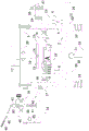
FIG. 1 is a schematic structural view of the strut assembly of the present invention without support;
FIG. 2 is a schematic structural view of the connection between the connecting plate and the limiting rod;
FIG. 3 is a schematic structural view of the connection of the pressing plate, the pressing rod and the pressing block when the supporting rod set supports;
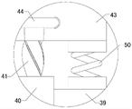
FIG. 4 is an enlarged partial view of portion A of FIG. 1;
FIG. 5 is an enlarged view of part B of FIG. 1;
FIG. 6 is a schematic structural diagram of the connection of the push plate, the push rod, the push block and the return spring set;
in the drawings, the reference numbers: 1. a filter plate; 2. a work box; 3. feeding a block; 4. a delivery pipe; 5. a delivery pump; 6. a fixed block; 7. a limiting block; 8. a rubber dredging rod; 9. rotating the handle; 10. a connecting frame; 11. a rotating shaft; 12. a first set of springs; 13. pushing the plate; 14. a push rod; 15. a push block; 16. a squeegee; 17. pressing a plate; 18. a pressure lever; 19. briquetting; 20. a magnet stone group; 21. a strut group; 22. a reinforcing bar set; 23. a separation tank; 24. a blocking cover; 25. a liquid discharge pipe; 26. a communicating pipe; 27. a nut; 28. an upper plate body; 29. a lower plate body; 30. a support pillar; 31. a universal ball; 32. a second set of springs; 33. down-sucking the iron blocks; 34. a support table; 35. an adsorption tank; 36. an air inlet pipe; 37. a filter screen; 38. an exhaust fan; 39. maintaining the guard plate; 40. a spiral tube; 41. a screw rod; 42. stirring blades; 43. a moving block; 44. a rotating sheet; 45. a connecting plate; 46. a limiting rod; 47. a pillar; 48. a lever; 49. pressing the handle; 50. a rebound spring; 51. and a return spring set.
Detailed Description
The following detailed description of the embodiments of the present invention is provided with reference to the accompanying drawings and examples. The following examples are intended to illustrate the invention, but are not intended to limit the scope of the invention.
As shown in fig. 1 to 6, the biogas residue and liquid separator of the utility model comprises a filter plate 1 and a working box 2, wherein the working box 2 is internally provided with a working chamber, the top end of the working box 2 is provided with a feed inlet in a communicating manner, a sealing screw at the feed inlet is provided with a feed block 3, the rear side of the working box 2 is provided with a maintenance port in a communicating manner, a sealing screw at the maintenance port is provided with a T-shaped maintenance block, the lower part of the right side of the working box 2 is provided with a conveying pipe 4 in a communicating manner, and the conveying pipe 4 is communicated with a conveying pump 5 in a sealing manner; still include two sets of fixed blocks 6, two sets of jump rings and two sets of stoppers 7, two sets of fixed blocks 6 are installed respectively in work box 2 left side and interior right side, two sets of fixed block 6 inboards all are provided with the spacing groove, the one end of two sets of jump rings is connected with two sets of spacing grooves respectively, the other end of two sets of jump rings is connected with two sets of stoppers 7 respectively, filter 1 clamps between two sets of stoppers 7, filter 1 left end and right-hand member are located two sets of spacing inslots respectively, and filter 1 top and bottom left side and filter 1 top and bottom right side paste tightly with two sets of spacing inslot lateral walls respectively, and filter 1 front side wall and back side wall all paste tightly with work box 2 inside wall, filter 1 back side wall pastes tightly with "T" type maintenance blockking front side wall, filter 1 bottom middle part is provided with the bearing frame, and rotatable ball bearing that is fixed in the, The rotary handle 9, the connecting frame 10 and the rotary shaft 11, the rotary handle 9 is rotatably arranged at the bottom end of the connecting frame 10, the bottom end of the rotary shaft 11 is connected with the connecting frame 10, the top end of the rotary shaft 11 is inserted and fixed inside the ball bearing, the rotary handle further comprises a plurality of groups of first sleeve springs 12 and a plurality of groups of first telescopic pipes, one ends of the plurality of groups of first sleeve springs 12 are all connected with the top end of the connecting frame 10, the other ends of the plurality of groups of first sleeve springs 12 are respectively connected with a plurality of groups of rubber dredging rods 8, the plurality of groups of first sleeve springs 12 are respectively sleeved outside the plurality of groups of first telescopic pipes, the rotary handle further comprises a push plate 13, a push rod 14, a push block 15 and a scraper 16, the push plate 13 is positioned outside the working box 2, the push block 15 and the scraper 16 are both positioned inside the working box 2, the scraper 16 is arranged at the bottom end of the push block, the bottom end of the scraping plate 16 is attached to the top side wall of the filter plate 1, the front end of the push rod 14 is connected with the push plate 13, and the rear end of the push rod 14 is connected with the push block 15; the filter plate can be clamped and fixed by driving two groups of limiting blocks through two groups of snap springs, so that the filter plate can be conveniently pulled out and detached from a maintenance port by hand, meanwhile, after the filter plate is detached, a rotating handle can be rotated by hand to drive a plurality of groups of rubber dredging rods on a connecting frame to rotate, the plurality of groups of rubber dredging rods are slightly inserted into filter holes of the filter plate, so that the plugging of the filter plate can be conveniently poked and dredged by the plurality of groups of rubber dredging rods, the filter plate is not easy to be pierced by the aid of self-softness of rubber materials, the first set of spring assists the rubber dredging rods to move longitudinally, the rubber dredging rods can rotate smoothly, the first telescopic pipe can improve the supporting effect and assist the first set of spring to be not easy to distort, in the use process of the filter plate, the push plate can be manually pushed to drive a scraper on a push block to temporarily push aside the filter plate, the filter plate is temporarily not blocked, the use reliability of the filter plate is improved, and the filter plate can be conveniently treated when being blocked, so that the use reliability of the filter plate is improved, and the practicability is reduced.
The utility model discloses a natural pond sediment natural pond liquid separating centrifuge still includes clamp plate 17, depression bar 18 and briquetting 19, and the clamp plate 17 top is connected with the slipmat, and depression bar 18 top is connected with clamp plate 17, and feed sprue 3 is last to communicate to be provided with first logical groove, and rotatable the fixing has first ball group in first logical groove inside wall, and depression bar 18 bottom passes first ball group and stretches into to the inside of work box 2 and is connected with briquetting 19; it can press through handheld clamp plate, makes it drive the briquetting and presses the natural pond sediment, improves the dehydration effect, and the just depression bar of first ball composition slides in the same direction as smooth, and the slipmat makes things convenient for antiskid.
The utility model discloses a biogas residue and biogas slurry separator, the bottom end of a pressing plate 17 and the top end of a feeding block 3 are both provided with a magnet sheet group 20, the separator also comprises a support rod group 21, both ends of the top and bottom of the support rod group 21 are both provided with iron sheets, the iron sheet group positioned above and the iron sheet group positioned below are respectively adsorbed at the magnet sheet group 20 positioned above and the magnet sheet group 20 positioned below; it can prop up the briquetting when the briquetting is idle through the branch group, makes things convenient for the work box to carry out normal use, and iron sheet group adsorbs and just supports dismouting at magnet stone sheet group prescription.
The utility model discloses a marsh gas sediment natural pond liquid separating centrifuge still includes reinforcing bar group 22 and separator box 23, the separator box 23 is inside to be provided with the separation chamber, separator box 23 top intercommunication is provided with the manhole, and the screw is equipped with fender lid 24 in manhole department, separator box 23 bottom sealing intercommunication has fluid-discharge tube 25, and be provided with the flowing back valve in fluid-discharge tube 25 department, conveyer pipe 4 right side output and separator box 23 left side sealing intercommunication, reinforcing bar group 22 both ends are connected work box 2 right side and separator box 23 left side, still include communicating pipe 26 and two sets of nuts 27, the lateral wall of communicating pipe 26 is provided with first screw thread, fender lid 24 top intercommunication is provided with the displacement hole, the bottom of communicating pipe 26 is in proper order the screw pass one of two sets of nuts 27, pass the displacement hole and the screw pass another set of nuts 27 in two sets of nuts 27, two sets of nuts 27 paste tight fender lid 24 top lateral wall and bottom lateral wall respectively, the communicating pipe 26 is attached to the inner side wall of the displacement hole, and the left side and the right side of the delivery pump 5 are connected to the right side of the working box 2 and the left side of the separation box 23; it can make things convenient for natural pond liquid to stew through the separator box, make its inside fluid layering, oil reservoir accessible communicating pipe carries out the suction with it with the help of external suction pump, alleviate the follow-up processing burden, meanwhile, can be through two sets of nuts of manual unscrewing, make two sets of nuts no longer paste tight fender lid, manual longitudinal movement communicating pipe to suitable position, screw up two sets of nuts and make two sets of nuts paste tight fender lid once more, thereby carry out spacing fixed communicating pipe, make communicating pipe suction height can conveniently adjust, the adaptability is improved, it is fixed to make things convenient for the separator box to consolidate the pole group.
The utility model discloses a biogas residue and liquid separator, which also comprises an upper plate body 28, a lower plate body 29, a support column 30 and a universal ball 31, wherein the bottom end of the support column 30 is arranged at the top end of the lower plate body 29, the top end of the support column 30 is connected with the universal ball 31, the bottom end of the upper plate body 28 is provided with a spherical groove, the universal ball 31 is positioned inside the spherical groove, the universal ball 31 can rotate relative to the spherical groove, and the working box 2 is arranged at the top end of the upper plate body 28; it can be through the design of universal ball rotatory spherical groove relatively, and manual stirring work box makes it to conveyer pipe direction slope, and under the action of gravity, can conveniently unload totally and accelerate the speed of unloading when the conveyer pipe is unloaded, improves its practicality.
The utility model discloses a natural pond sediment natural pond liquid separating centrifuge, still include four groups of connection blocks, four groups of second cover springs 32, four groups of flexible pipe of second and four groups of lower connection blocks, four groups of second cover springs 32's one end is connected with four groups of last connection blocks respectively, four groups of second cover springs 32's the other end is connected with four groups of lower connection blocks respectively, four groups of flexible pipe of second's one end is connected with four groups of last connection blocks respectively, four groups of second flexible pipe's the other end is connected with four groups of lower connection blocks respectively, four groups of second cover springs 32 suit is in four groups of second flexible pipe outsides respectively, four groups of last connection blocks and four groups of lower connection blocks all set up to the iron piece, still include four groups of last magnet piece and four groups of lower magnet piece 33, four groups of last connection blocks adsorb respectively in four groups of last magnet piece bottoms, four groups of lower connection blocks adsorb respectively on four groups of last magnet, Four groups of lower magnet blocks 33 are respectively arranged at the left front side, the right front side, the left rear side and the right rear side of the top end of the lower plate body 29; it can carry on spacingly through the relative fixation of connecting block and magnet piece mutual adsorption convenience to upper and lower plate body, when last plate body rotates, makes the second cover spring dismantle through four group's second cover springs of manual extrusion, and is no longer spacing, and convenient upper plate body rotates and rotates, and the difficult distortion of four group's second cover springs of the supplementary four group of second cover springs of the scalable pipe of four group's second is when supporting.
The utility model discloses a natural pond sediment natural pond liquid separating centrifuge still includes brace table 34 and adsorption tank 35, the workstation is installed in the left side of work box 2, adsorption tank 35 is installed on brace table 34 top, adsorption tank 35 is inside to be provided with the absorption chamber, adsorption tank 35 is inside to have placed the adsorption carbon, the sealed intercommunication in adsorption tank 35 right side below has intake pipe 36, intake pipe 36 output intercommunication has filter screen 37, intake pipe 36 input and work box 2 left side top sealed intercommunication, the sealed intercommunication in adsorption tank 35 rear side top has exhaust fan 38, adsorption tank 35 top intercommunication is provided with the maintenance hole, and the sealed spiral at maintenance hole department is equipped with maintenance board 39, still include spiral pipe 40, hob 41, stirring leaf 42 and movable block 43, spiral pipe 40 seals marsh gas maintenance board 39 top, and spiral pipe 40 and maintenance board 39 top intercommunication, the bottom of hob 41 spiral dress is to the inside of spiral pipe 40 top and is connected with stirring leaf 42 to the absorption intracavity portion, the top end of the screw rod 41 is fixedly provided with a rotating sheet 44, the bottom end of the moving block 43 is provided with a rotating groove, the rotating sheet 44 is positioned in the rotating groove, and the rotating sheet 44 can rotate relative to the rotating groove; the biogas can be guided into the adsorption box through the cooperation of gas and an exhaust fan, the biogas taste is adsorbed through adsorption carbon, the adsorbed air is discharged from the exhaust fan, the maintenance hole cleans the interior of the adsorption box, the strong biogas taste in the biogas process can be conveniently treated, thereby reducing the work hazard and improving the practicability, the exhaust fan is a common electric device in the market, can be used only by being electrically connected according to the use instruction purchased together when being purchased for use, the adsorbed carbon is a common material in the market and can be bought for reuse, so the description is omitted, and at the same time, can make spiral pipe and hob cooperate through the longitudinal movement movable block, can make the in-process of stirring leaf longitudinal movement rotate the stirring at the design that rotates the inslot internal rotation through the rotor plate, make the adsorbed carbon can facilitate the use more even, improve its use reliability.
The utility model discloses a natural pond sediment natural pond liquid separating centrifuge still includes two sets of connecting plates 45 and two sets of gag lever post 46, two sets of connecting plates 45 install respectively at maintenance board 39 top left half regional front side and rear side, two sets of gag lever post 46 front ends are installed respectively and are located connecting plate 45 rear side top and below of front side, two sets of gag lever post 46 rear ends are installed respectively and are located connecting plate 45 front side top and below of rear side, still include pillar 47, lever 48 and pressure handle 49, pillar 47 is installed at movable block 43 top, lever 48 right-hand member hub connection is on pillar 47 top, pressure handle 49 is installed at lever 48 left end, lever 48 is placed between two sets of connecting plates 45, and lever 48 is placed between two sets of gag lever post 46; its staff can press the handle through handheld, and the longitudinal movement who presses the handle and then make the movable block longitudinal movement under the spacing of two sets of connecting plates and two sets of gag lever posts, and it is more convenient to use, and when setting up, the gag lever post interval of pressing the handle and being located the below is longer than pillar and the gag lever post interval that is located the below, and is more laborsaving.
The utility model discloses a biogas residue and biogas slurry separator, which also comprises two groups of rebound springs 50, wherein the top ends of the two groups of rebound springs 50 are respectively arranged at the left side and the right side of the bottom end of the moving block 43, and the bottom ends of the two groups of rebound springs 50 are arranged at the top end of the maintenance plate 39; the movable block can conveniently and automatically move downwards without external force through the elasticity of the two groups of rebound springs, and the labor is saved.
The utility model discloses a natural pond sediment natural pond liquid separating centrifuge, the lateral wall intercommunication is provided with the second through groove before the work box 2, and in the rotatable second ball group that is fixed with of second through groove inside wall, 14 rear ends of push rod pass the second ball group and stretch into to the work box 2 inside, the rotatable close cover that pastes in the push rod 14 outside is equipped with the sealing washer, the sealing washer pastes the interior front side wall of work box 2 tightly, still include reset spring group 51, reset spring group 51's both ends are connected with push pedal 13 rear side and work box 2 front side respectively; it can be through the supplementary push rod of second ball group slip more smoothly, reduces frictional force, and elasticity through reset spring group self makes things convenient for the automatic forward pop-up under the push pedal does not have the extruded condition of external force, and only need to push back when scraping and can accomplish, uses laborsavingly more.
The utility model discloses a biogas residue and biogas slurry separator, which can clamp and fix a filter plate by two sets of snap springs driving two sets of stoppers when in operation, so that the filter plate can be conveniently drawn out and disassembled from a maintenance port by hand, meanwhile, after the filter plate is disassembled, a rotating handle can be rotated by hand to drive a plurality of sets of rubber dredging rods on a connecting frame to rotate, the plurality of sets of rubber dredging rods are slightly inserted into filter holes of the filter plate, so that the plurality of sets of rubber dredging rods can conveniently poke and dredge blockages of the filter plate, the self softness of rubber materials can not easily cause the filter plate to be pierced, a first set of spring can assist the rubber dredging rods to move longitudinally, the rubber dredging rods can rotate smoothly, a first telescopic pipe can improve the supporting effect and assist the first set of spring not to be distorted and deformed easily when the first telescopic pipe is used, the push plate can be pushed manually to drive the scraper on the push block to temporarily push the blocking object on the filter plate aside, so that the filter plate is not blocked temporarily, the use reliability of the filter plate is improved, the filter plate can be conveniently treated when being blocked, the use reliability of the filter plate is improved, and the practicability is reduced; the pressing plate can be pressed by a hand, so that the pressing plate is driven to press biogas residues, the dehydration effect is improved, the first ball group facilitates the smooth sliding of the pressing rod, and the non-slip mat facilitates the non-slip; the pressing block can be supported by the support rod group when the pressing block is idle, so that the working box can be conveniently used normally, and the iron sheet group is adsorbed at the magnet sheet group to facilitate the disassembly and assembly of the support rod; the biogas slurry can be conveniently kept still through the separation box, so that oil in the separation box can be layered, an oil layer can be sucked out through the communicating pipe by virtue of an external suction pump, the burden of subsequent treatment is reduced, meanwhile, the two groups of nuts can be loosened manually, so that the two groups of nuts are not attached to the baffle cover any more, the communicating pipe is moved to a proper position manually and longitudinally, the two groups of nuts are screwed down to enable the two groups of nuts to be attached to the baffle cover again, so that the communicating pipe is limited and fixed, the sucking height of the communicating pipe can be conveniently adjusted, the adaptive capacity is improved, and the; the universal ball can rotate relative to the spherical groove, the working box is manually stirred to incline towards the conveying pipe, and the conveying pipe can be conveniently and completely unloaded and the unloading speed is accelerated when unloading the material, so that the practicability is improved; the upper plate body and the lower plate body can be mutually adsorbed through the connecting block and the magnet block to conveniently limit the relative fixation of the upper plate body and the lower plate body, when the upper plate body rotates, the four groups of second sleeve springs are manually extruded to disassemble the second sleeve springs, the limiting is not needed, the rotation and the rotation of the upper plate body are convenient, and the four groups of second telescopic pipes assist the four groups of second sleeve springs to be not easy to distort and deform during the supporting; can be guided into the adsorption box by matching with the exhaust fan through gas, adsorbs the methane taste through adsorption carbon, discharges the adsorbed air from the exhaust fan, cleans the interior of the adsorption box through the maintenance hole, can conveniently process the strong methane taste in the methane process, thereby reducing the work hazard and improving the practicability, the exhaust fan is a common electric device in the market, can be used only by being electrically connected according to the use instruction purchased together when being purchased for use, the adsorbed carbon is a common material in the market and can be bought for reuse, so the description is omitted, and at the same time, the spiral pipe can be matched with the spiral rod by longitudinally moving the moving block, and the stirring blade can be rotated and stirred in the longitudinal moving process of the stirring blade by the design that the rotating sheet can rotate in the rotating groove, so that the carbon adsorption can be more uniform and the use reliability of the carbon adsorption can be improved; the working personnel can carry out longitudinal movement of the pressing handle under the limiting of the two groups of connecting plates and the two groups of limiting rods by holding the pressing handle by hands so as to enable the moving block to move longitudinally, the use is more convenient, and the distance between the pressing handle and the limiting rod positioned below is longer than that between the support and the limiting rod positioned below during setting, so that the labor is saved; the moving block can conveniently and automatically move downwards without external force action through the elasticity of the two groups of rebound springs, so that labor is saved; can organize supplementary push rod through the second ball and slide more smoothly, reduce frictional force, make things convenient for the push pedal through reset spring group self and do not have automatic forward pop-up under the extruded condition of external force, and only need to push away after when scraping and can accomplish, use more laborsavingly.
The utility model discloses a natural pond sediment natural pond liquid separating centrifuge, it is above the mounting means of all parts, connected mode or set up the mode and be marsh gas, riveting or other common mechanical mode, wherein can slide/rotate fixedly promptly for slide/not dropping under the rotation state, seal the intercommunication and seal when two connecting pieces communicate promptly, and the concrete structure of its all parts, model and coefficient index are its from the area technique, as long as can reach all implementation of its beneficial effect, above-mentioned all with the electric module and be the common electrical part in market with electrical apparatus, buy when using back only need connect according to the mutual electricity of the instruction manual of buying back together and can use, and control module is its common from taking the module, the event is all no longer repeated here.
The utility model relates to a biogas residue and liquid separator, under the condition of not being explained reversely, the directional words contained in the terms such as 'up-down, left-right, front-back, inside-outside and vertical and horizontal' only represent the direction of the term under the normal use state, or be a trivial term understood by those skilled in the art, and should not be considered as limiting the term, at the same time, the numerical terms "first," "second," and "third," etc. do not denote any particular quantity or order, but rather are used to distinguish one from another, furthermore, the terms "comprises," "comprising," or any other variation thereof, are intended to cover a non-exclusive inclusion, such that a process, method, article, or apparatus that comprises a list of elements does not include only those elements, but also includes other elements not expressly listed or inherent to such process, method, article, or apparatus.
The foregoing is only a preferred embodiment of the present invention, and it should be noted that, for those skilled in the art, a plurality of modifications and variations can be made without departing from the technical principle of the present invention, and these modifications and variations should also be regarded as the protection scope of the present invention.
Claims (10)
1. A biogas residue and biogas slurry separator comprises a filter plate (1) and a working box (2), wherein a working chamber is arranged in the working box (2), the top end of the working box (2) is provided with a feed inlet in a communicating manner, a feed plugging block (3) is arranged at the feed inlet in a sealing and threaded manner, the rear side of the working box (2) is provided with a maintenance port in a communicating manner, a T-shaped maintenance plugging block is arranged at the maintenance port in a sealing and threaded manner, a conveying pipe (4) is arranged below the right side of the working box (2) in a communicating manner, and a conveying pump (5) is arranged at the conveying pipe (4) in a sealing; the device is characterized by also comprising two groups of fixed blocks (6), two groups of clamp springs and two groups of limit blocks (7), wherein the two groups of fixed blocks (6) are respectively arranged at the left side and the right side in the working box (2), the inner sides of the two groups of fixed blocks (6) are respectively provided with limit grooves, one ends of the two groups of clamp springs are respectively connected with the two groups of limit grooves, the other ends of the two groups of clamp springs are respectively connected with the two groups of limit blocks (7), the filter plate (1) is clamped between the two groups of limit blocks (7), the left end and the right end of the filter plate (1) are respectively positioned in the two groups of limit grooves, the left side of the top end and the bottom end of the filter plate (1) and the right side of the top end and the bottom end of the filter plate (1) are respectively tightly attached to the inner side walls of the two groups of limit grooves, the front side wall and the rear side wall of, the bearing seat is internally and rotatably fixed with a ball bearing, and also comprises a plurality of groups of rubber dredging rods (8), a rotating handle (9), a connecting frame (10) and a rotating shaft (11), wherein the rotating handle (9) is rotatably arranged at the bottom end of the connecting frame (10), the bottom end of the rotating shaft (11) is connected with the connecting frame (10), the top end of the rotating shaft (11) is inserted and fixed in the ball bearing, the bearing seat also comprises a plurality of groups of first sleeve springs (12) and a plurality of groups of first telescopic pipes, one end of each group of first sleeve springs (12) is connected with the top end of the connecting frame (10), the other ends of the plurality of groups of first sleeve springs (12) are respectively connected with the plurality of groups of rubber dredging rods (8), one end of each group of first telescopic pipe is connected with the top end of the connecting frame (10), the other ends of the plurality of first telescopic pipes are respectively connected with the plurality of rubber dredging rods (8), and the plurality of first sleeve, still include push pedal (13), push rod (14), ejector pad (15) and scraper blade (16), push pedal (13) are located work box (2) outside, inside ejector pad (15) and scraper blade (16) all are located work box (2), install in ejector pad (15) bottom scraper blade (16), and scraper blade (16) bottom pastes tight filter (1) top lateral wall, push rod (14) front end is connected with push pedal (13), push rod (14) rear end is connected with ejector pad (15).
2. The biogas residue and liquid separator according to claim 1, further comprising a pressing plate (17), a pressing rod (18) and a pressing block (19), wherein the top end of the pressing plate (17) is connected with a non-slip mat, the top end of the pressing rod (18) is connected with the pressing plate (17), the feeding block (3) is provided with a first through groove in a communicating manner, a first ball group is rotatably fixed on the inner side wall of the first through groove, and the bottom end of the pressing rod (18) penetrates through the first ball group and extends into the working box (2) to be connected with the pressing block (19).
3. The biogas residue and liquid separator according to claim 2, wherein the bottom end of the pressing plate (17) and the top end of the feed block (3) are provided with a magnet sheet group (20), the separator further comprises a support rod group (21), iron sheets are arranged at the top and bottom ends of the support rod group (21), and the upper iron sheet group and the lower iron sheet group are respectively adsorbed at the upper magnet sheet group (20) and the lower magnet sheet group (20).
4. The biogas residue and liquid separator according to claim 3, further comprising a reinforcing rod group (22) and a separation box (23), wherein a separation chamber is arranged inside the separation box (23), a manhole is arranged at the top end of the separation box (23) in a communicating manner, a baffle cover (24) is screwed at the manhole, a liquid discharge pipe (25) is hermetically communicated with the bottom end of the separation box (23), a liquid discharge valve is arranged at the liquid discharge pipe (25), the right side output end of the conveying pipe (4) is hermetically communicated with the left side of the separation box (23), two ends of the reinforcing rod group (22) are connected with the right side of the working box (2) and the left side of the separation box (23), a communicating pipe (26) and two groups of nuts (27) are further included, a first thread is arranged on the outer side wall of the communicating pipe (26), a displacement hole is arranged at the top end of the baffle cover (24), and the bottom end of the communicating pipe (26) sequentially penetrates through one group, The conveying pump passes through the displacement hole and the other nut (27) of the two groups of nuts (27), the two groups of nuts (27) are respectively attached to the top side wall and the bottom side wall of the blocking cover (24), the communicating pipe (26) is attached to the inner side wall of the displacement hole, and the left side and the right side of the conveying pump (5) are connected to the right side of the working box (2) and the left side of the separation box (23).
5. The biogas residue and liquid separator according to claim 4, further comprising an upper plate body (28), a lower plate body (29), a support column (30) and a universal ball (31), wherein the bottom end of the support column (30) is mounted at the top end of the lower plate body (29), the top end of the support column (30) is connected with the universal ball (31), the bottom end of the upper plate body (28) is provided with a spherical groove, the universal ball (31) is located inside the spherical groove, the universal ball (31) can rotate relative to the spherical groove, and the work box (2) is mounted at the top end of the upper plate body (28).
6. The biogas residue and liquid separator according to claim 5, further comprising four sets of upper connecting blocks, four sets of second sleeve springs (32), four sets of second telescopic tubes and four sets of lower connecting blocks, wherein one ends of the four sets of second sleeve springs (32) are respectively connected with the four sets of upper connecting blocks, the other ends of the four sets of second sleeve springs (32) are respectively connected with the four sets of lower connecting blocks, one ends of the four sets of second telescopic tubes are respectively connected with the four sets of upper connecting blocks, the other ends of the four sets of second telescopic tubes are respectively connected with the four sets of lower connecting blocks, the four sets of second sleeve springs (32) are respectively sleeved outside the four sets of second telescopic tubes, the four sets of upper connecting blocks and the four sets of lower connecting blocks are respectively provided as iron blocks, and further comprising four sets of upper iron absorbing blocks and four sets of lower iron absorbing blocks (33), the four sets of upper connecting blocks are respectively adsorbed at the bottom ends of the four sets of upper iron absorbing, four groups of upper iron absorbing blocks are respectively arranged at the left front side, the right front side, the left rear side and the right rear side of the bottom end of the upper plate body (28), and four groups of lower iron absorbing blocks (33) are respectively arranged at the left front side, the right front side, the left rear side and the right rear side of the top end of the lower plate body (29).
7. The biogas residue and liquid separator according to claim 6, further comprising a support table (34) and an adsorption tank (35), wherein the work table is installed on the left side of the work tank (2), the adsorption tank (35) is installed on the top end of the support table (34), an adsorption cavity is arranged inside the adsorption tank (35), adsorption carbon is placed inside the adsorption tank (35), an air inlet pipe (36) is hermetically communicated with the lower portion of the right side of the adsorption tank (35), the output end of the air inlet pipe (36) is communicated with a filter screen (37), the input end of the air inlet pipe (36) is hermetically communicated with the upper portion of the left side of the work tank (2), an exhaust fan (38) is hermetically communicated with the upper portion of the rear side of the adsorption tank (35), a maintenance hole is communicatively connected with the top end of the adsorption tank (35), a maintenance plate (39) is hermetically screwed at the maintenance hole, and further comprising a spiral pipe (40), a spiral rod, the spiral pipe (40) seals marsh gas and is on maintenance board (39) top, and spiral pipe (40) and maintenance board (39) top intercommunication, screw rod (41) bottom spiral shell dress to spiral pipe (40) top inside and the spiral shell is connected with stirring leaf (42) to the absorption intracavity portion, fixed being provided with in spiral rod (41) top rotates piece (44), movable block (43) bottom is provided with rotates the groove, rotates piece (44) and is located and rotates inslot portion, and rotates piece (44) and can rotate the groove rotation relatively.
8. The biogas residue and liquid separator according to claim 7, further comprising two sets of connecting plates (45) and two sets of limiting rods (46), wherein the two sets of connecting plates (45) are respectively installed at the front side and the rear side of the left half area at the top end of the maintenance plate (39), the front ends of the two sets of limiting rods (46) are respectively installed above and below the rear side of the connecting plate (45) at the front side, the rear ends of the two sets of limiting rods (46) are respectively installed above and below the front side of the connecting plate (45) at the rear side, and further comprising a support column (47), lever (48) and pressure handle (49), pillar (47) are installed on movable block (43) top, and lever (48) right-hand member hub connection is on pillar (47) top, presses handle (49) to install at lever (48) left end, and lever (48) are placed between two sets of connecting plates (45), and lever (48) are placed between two sets of gag lever post (46).
9. The biogas residue and liquid separator according to claim 8, further comprising two sets of rebound springs (50), wherein the top ends of the two sets of rebound springs (50) are respectively installed at the left side and the right side of the bottom end of the moving block (43), and the bottom ends of the two sets of rebound springs (50) are both installed at the top end of the maintenance plate (39).
10. The biogas residue and liquid separator according to claim 9, wherein a second through groove is formed in the front side wall of the working box (2) in a communicating manner, a second ball group is rotatably fixed on the inner side wall of the second through groove, the rear end of the push rod (14) penetrates through the second ball group and extends into the working box (2), a sealing ring is rotatably attached to the outer side of the push rod (14) in a close manner, the sealing ring is attached to the inner front side wall of the working box (2), the separator further comprises a return spring group (51), and two ends of the return spring group (51) are respectively connected with the rear side of the push plate (13) and the front side of the working box (2).
Priority Applications (1)
| Application Number | Priority Date | Filing Date | Title |
|---|---|---|---|
| CN201920928702.4U CN210170921U (en) | 2019-06-19 | 2019-06-19 | Biogas residue and biogas slurry separator |
Applications Claiming Priority (1)
| Application Number | Priority Date | Filing Date | Title |
|---|---|---|---|
| CN201920928702.4U CN210170921U (en) | 2019-06-19 | 2019-06-19 | Biogas residue and biogas slurry separator |
Publications (1)
| Publication Number | Publication Date |
|---|---|
| CN210170921U true CN210170921U (en) | 2020-03-24 |
Family
ID=69838247
Family Applications (1)
| Application Number | Title | Priority Date | Filing Date |
|---|---|---|---|
| CN201920928702.4U Active CN210170921U (en) | 2019-06-19 | 2019-06-19 | Biogas residue and biogas slurry separator |
Country Status (1)
| Country | Link |
|---|---|
| CN (1) | CN210170921U (en) |
Cited By (1)
| Publication number | Priority date | Publication date | Assignee | Title |
|---|---|---|---|---|
| CN115069000A (en) * | 2022-06-27 | 2022-09-20 | 中建二局第二建筑工程有限公司 | Indoor ski field effluent disposal system |
-
2019
- 2019-06-19 CN CN201920928702.4U patent/CN210170921U/en active Active
Cited By (2)
| Publication number | Priority date | Publication date | Assignee | Title |
|---|---|---|---|---|
| CN115069000A (en) * | 2022-06-27 | 2022-09-20 | 中建二局第二建筑工程有限公司 | Indoor ski field effluent disposal system |
| CN115069000B (en) * | 2022-06-27 | 2023-09-22 | 中建二局第二建筑工程有限公司 | Indoor skifield wastewater treatment system |
Similar Documents
| Publication | Publication Date | Title |
|---|---|---|
| CN108016067A (en) | A kind of kitchen garbage equipment for separating liquid from solid | |
| CN210170921U (en) | Biogas residue and biogas slurry separator | |
| CN109224575B (en) | Municipal sewage treatment filters auxiliary device with debris | |
| CN205084471U (en) | Secondary plate and frame filter press for chemical industry | |
| CN211198675U (en) | Heavy metal separation and recovery device for electroplating wastewater | |
| CN210660177U (en) | Dust collector for mine protection | |
| CN108151517A (en) | Spiral cement powder drying equipment for building | |
| CN209997933U (en) | Impurity screening device in kinds of granule preparation processes | |
| CN213652243U (en) | A sludge treatment equipment for hydraulic engineering | |
| CN210237278U (en) | Sewage treatment equipment for cement plant | |
| CN215093791U (en) | A side cut device for processing of AR printed matter | |
| CN210786370U (en) | Converter discharging, filtering and classifying device | |
| CN209872609U (en) | Meat processing wastewater treatment equipment | |
| CN210393795U (en) | Horizontal flow type dissolved air flotation machine | |
| CN210209011U (en) | Automatic submerged arc surfacing equipment | |
| CN220695960U (en) | High pressure filter of stability | |
| CN210126310U (en) | Agricultural is with high-efficient intelligent solid-liquid separation equipment | |
| CN210419528U (en) | Ink wastewater treatment all-in-one machine | |
| CN220578416U (en) | Tablet loading attachment | |
| CN211650373U (en) | Kitchen oil smoke purification treatment device | |
| CN220362993U (en) | 3D prints internal stress relief apparatus of moulding | |
| CN219450260U (en) | Water slurry sand removing device for packaging paper production | |
| CN210283170U (en) | Extruder exhaust treatment device | |
| CN108636012A (en) | A kind of industrial chemicals dust absorbing device | |
| CN220681292U (en) | Environment-friendly tire banbury mixer material feeding unit |
Legal Events
| Date | Code | Title | Description |
|---|---|---|---|
| GR01 | Patent grant | ||
| GR01 | Patent grant |