CN210155587U - Dustproof computer case - Google Patents
Dustproof computer case Download PDFInfo
- Publication number
- CN210155587U CN210155587U CN201920913695.0U CN201920913695U CN210155587U CN 210155587 U CN210155587 U CN 210155587U CN 201920913695 U CN201920913695 U CN 201920913695U CN 210155587 U CN210155587 U CN 210155587U
- Authority
- CN
- China
- Prior art keywords
- dustproof
- case
- case body
- slideway
- dust
- Prior art date
- Legal status (The legal status is an assumption and is not a legal conclusion. Google has not performed a legal analysis and makes no representation as to the accuracy of the status listed.)
- Expired - Fee Related
Links
Images


Abstract
The utility model relates to a dustproof quick-witted case of computer. The dustproof case comprises a case body and a dustproof device, the case body is connected with the dustproof device in a clamped mode, a slide rail is arranged on the front end face of the case body, the front portion of the case body is connected with a locking device in a sliding mode through the slide rail, a guide block is arranged on the inner side of the front portion of the case body, a clamping groove is formed in the lower portion of the guide block, a ventilation frame located on the rear side of the dustproof device is arranged on the front portion of the case body, a rotating shaft is fixedly arranged in the middle of the ventilation frame, a plurality of fan blades are arranged in the central symmetry of the outer edge of the. This machine case can realize reducing the dust effectively and get into quick-witted incasement portion, and the dust screen of use is dismantled conveniently, is convenient for regularly clear up the dust screen, helps the life of dust screen, has also indirectly improved the heat-sinking capability of quick-witted case.
Description
Technical Field
The utility model relates to a computer fittings field, more specifically relates to a dustproof quick-witted case of computer.
Background
The case is used as a part of computer accessories and mainly plays a role in placing and fixing the computer accessories to play a role in supporting and protecting. In addition, the computer case has an important role in shielding electromagnetic radiation. The chassis typically includes a housing, brackets, various switches on the panel, indicator lights, etc. The casing is made of steel plates and plastics, has high hardness and mainly plays a role in protecting elements in the case, and the bracket is mainly used for fixing the mainboard, the power supply and various drivers.
In the use process of the computer, dust in the air can inevitably enter the interior of the case, so that the heat dissipation effect of the case is greatly reduced, and even potential safety hazards are buried, on one hand, the service life of the fan can be influenced, on the other hand, electrical elements in the case can be short-circuited or burnt, and in case of serious conditions, a fire disaster can be caused, and great loss is caused.
SUMMERY OF THE UTILITY MODEL
1. Technical problem to be solved
To the problem that exists among the prior art, the utility model aims to provide a computer case that prevents dust, it can realize reducing the dust effectively and get into quick-witted incasement portion, and the dust screen of use dismantles conveniently, is convenient for regularly clear up the dust screen, helps the life of dust screen, has also indirectly improved the heat-sinking capability of quick-witted case.
2. Technical scheme
In order to solve the above problems, the utility model adopts the following technical proposal.
The utility model provides a computer case that prevents dust, it includes machine case main part and dust keeper, machine case main part and dust keeper joint are connected, the terminal surface is equipped with the slide rail before the machine case main part, machine case main part front portion has locking device through slide rail sliding connection, machine case main part front portion inboard is equipped with the guide block, the guide block lower part is dug there is the draw-in groove, machine case main part front portion is equipped with the ventilation frame that is located the dust keeper rear side, the fixed pivot that is equipped with in ventilation frame middle part, pivot outer fringe central symmetry is equipped with a plurality of flabellums, the fixed power that is equipped with in ventilation frame rear end, can realize reducing the dust effectively and get into quick-witted incasement portion, the dust screen of use dismantles conveniently, be convenient for.
Further, the upper side and the lower side of the dustproof device are symmetrically provided with clamping plates connected with the clamping grooves in a clamped mode, a dustproof window is arranged between the clamping plates, the left end of the dustproof window is provided with a handle, the rear portion of the dustproof window is fixedly provided with a spring bolt, the middle of the spring bolt is provided with a notch, and a pushing block is arranged between the right end face of the spring bolt and the notch.
Further, locking device includes the body, baffle and slide bar, be equipped with the spring between baffle and the body, the body left part is excavated there are first slide and second slide, body upper portion is equipped with the stopper with the notch joint, body upper portion is equipped with the spacing groove with promote a joint, slide bar left end rear portion is equipped with the guide post, the slide bar other end rotates through round pin axle and quick-witted case main part to be connected, the downside matches and is equipped with the slider with slide rail complex on the body bottom, first slide and second slide left side junction shape are heart type, the height on first slide right side is higher than the height on second slide right side.
Furthermore, the front end face of the case body is provided with a base plate positioned below the limiting block and the limiting groove, and the left end of the base plate is inclined.
3. Advantageous effects
Compared with the prior art, the utility model has the advantages of:
(1) this scheme can realize reducing the dust effectively and get into quick-witted incasement portion, and the dust screen of use is dismantled conveniently, is convenient for regularly clear up the dust screen, helps the life of dust screen, has also indirectly improved the heat-sinking capability of quick-witted case.
(2) This use novel dustproof device who adopts has reduced the dust effectively and has got into quick-witted incasement portion, helps prolonging the life of device, has improved the heat-sinking capability of quick-witted case moreover indirectly.
(3) The locking device that this device adopted has utilized mechanical principle ingeniously, is convenient for dismantle the clearance fast to dustproof window, has avoided the trouble of traditional dustproof window difficult clearance.
Drawings
Fig. 1 is a schematic view of the overall structure of the present invention.
Fig. 2 is a schematic structural view of the dustproof device of the present invention.
Fig. 3 is a schematic structural diagram of the guide block of the present invention.
Fig. 4 is a right side view of the present invention.
Fig. 5 is a schematic structural diagram of the locking device of the present invention.
Fig. 6 is a schematic view of the position relationship between the body and the backing plate of the present invention.
The reference numbers in the figures illustrate:
the anti-dust device comprises a case body 1, a dustproof device 2, a lock tongue 3, a pushing block 31, a notch 32, a locking device 4, a baffle 41, a spring 42, a limiting block 43, a limiting groove 44, a first slide rail 45, a second slide rail 46, a body 47, a slide rod 48, a guide column 49, a guide block 5, a clamping groove 6, a rotating shaft 7, fan blades 8, a ventilation frame 9, a power supply 10, a sliding block 11, a base plate 12 and a sliding rail 13.
Detailed Description
The technical solution in the embodiment of the present invention will be clearly and completely described below with reference to the accompanying drawings in the embodiment of the present invention; obviously, the described embodiments are only a part of the embodiments of the present invention, and not all embodiments, and all other embodiments obtained by those skilled in the art without any inventive work are within the scope of the present invention based on the embodiments of the present invention.
In the description of the present invention, it should be noted that the terms "upper", "lower", "inner", "outer", "top/bottom", and the like indicate orientations or positional relationships based on the orientations or positional relationships shown in the drawings, and are only for convenience of description and simplification of description, but do not indicate or imply that the device or element referred to must have a specific orientation, be constructed in a specific orientation, and be operated, and thus, should not be construed as limiting the present invention. Furthermore, the terms "first" and "second" are used for descriptive purposes only and are not to be construed as indicating or implying relative importance.
In the description of the present invention, it is to be noted that, unless otherwise explicitly specified or limited, the terms "mounted", "provided", "sleeved/connected", "connected", and the like are to be understood in a broad sense, such as "connected", which may be fixedly connected, detachably connected, or integrally connected; can be mechanically or electrically connected; they may be connected directly or indirectly through intervening media, or they may be interconnected between two elements. The specific meaning of the above terms in the present invention can be understood in specific cases to those skilled in the art.
Example 1:
referring to fig. 1, a computer dustproof case comprises a case body 1 and a dustproof device 2, the case body 1 is connected with the dustproof device 2 in a clamping mode, a slide rail 13 is arranged on the front end face of the case body 1, the front portion of the case body 1 is connected with a locking device 4 in a sliding mode through the slide rail 13, a guide block 5 is arranged on the inner side of the front portion of the case body 1, referring to fig. 3, a clamping groove 6 is formed in the lower portion of the guide block 5, referring to fig. 4, a ventilation frame 9 located on the rear side of the dustproof device 2 is arranged on the front portion of the case body 1, a rotating shaft 7 is fixedly arranged in the middle of the ventilation frame 9, a plurality of fan blades 8 are symmetrically arranged in the.
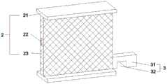
Referring to fig. 2, the upper and lower sides of the dust-proof device 2 are symmetrically provided with clamping plates 21 clamped with the clamping grooves 6, a dust-proof window 23 is arranged between the clamping plates 21, the left end of the dust-proof window 23 is provided with a handle 22, the rear part of the dust-proof window 23 is fixedly provided with a lock tongue 3, the middle part of the lock tongue 3 is provided with a notch 32, and a pushing block 31 is arranged between the right end surface of the lock tongue 3 and the notch 32.
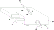
Referring to fig. 1 and 5, the locking device 4 includes a body 47, a baffle 41 and a slide bar 48, a spring 42 is disposed between the baffle 41 and the body 47, a first slide rail 45 and a second slide rail 46 are chiseled on the left portion of the body 47, a stop block 43 engaged with the notch 32 is disposed on the upper portion of the body 47, a stop groove 44 engaged with the pushing block 31 is disposed on the upper portion of the body 47, a guide post 49 is disposed on the rear portion of the left end of the slide bar 48, the other end of the slide bar 48 is rotatably connected with the main case body 1 through a pin shaft, slide blocks 11 engaged with the slide rails 13 are disposed on the upper and lower sides of the bottom of the body 47, a joint on the left side of the first slide rail 45 and the left side of the second slide rail 46.
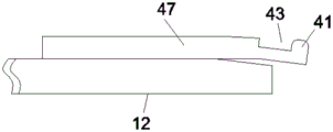
Referring to fig. 6, a pad 12 is disposed below the limiting block 43 and the limiting groove 44 on the front end surface of the case body 1, and the left end of the pad 12 is inclined.
The user at first holds dustproof device 2 and aims cardboard 21 at draw-in groove 6 in the guide block 5, holds handle 22 and promotes dust screen 23 inwards, because backing plate 12 highly differs, so stopper 43 and spacing groove 44 highly are raised, promote piece 31 and press stopper 43 joint inside spacing groove 44, notch 32 and stopper 43 joint continue to promote dust screen 23, slider 11 of body 47 lower part begins at the slide rail 11 of slide rail lower part13, the spring 42 is gradually elongated, the guide column 49 firstly enters the second slide way 46, when the guide column 49 moves to the joint of the left sides of the first slide way 45 and the second slide way 46, the force application is stopped, so that the dust screen 23 is fixed at the corresponding position, the trouble that the dust screen 23 shakes due to the vibration of the case is avoided, when the dust screen 23 needs to be detached, the handle 22 is continuously held by a hand to apply force to the dust screen 23, when the dust screen cannot be continuously moved inwards, the force application is stopped, but the handle 22 is continuously held by the hand, the guide column 49 enters the first slide way 45 to slide, the dust screen 23 starts to move outwards under the contraction force of the spring 42, and simultaneously, because the left side of the backing plate 12 is low in height, the height of the limit block 43 and the limit groove 44 is reduced, the limit block 43 is separated from the notch 32, the push block 31 is separated. This machine case can realize reducing the dust effectively and get into quick-witted incasement portion, and the dust screen of use is dismantled conveniently, is convenient for regularly clear up the dust screen, helps the life of dust screen, has also indirectly improved the heat-sinking capability of quick-witted case.
The above description is only the preferred embodiment of the present invention; the scope of the present invention is not limited thereto. Any person skilled in the art should also be able to cover the technical scope of the present invention by replacing or changing the technical solution and the improvement concept of the present invention with equivalents and modifications within the technical scope of the present invention.
Claims (4)
1. The utility model provides a computer case that prevents dust, includes chassis main part (1) and dust keeper (2), its characterized in that: case body (1) with dust keeper (2) joint is connected, the terminal surface is equipped with slide rail (13) before case body (1), case body (1) front portion is passed through slide rail (13) sliding connection has locking device (4), case body (1) front portion inboard is equipped with guide block (5), guide block (5) lower part is dug and is had draw-in groove (6), case body (1) front portion is equipped with and is located ventilation frame (9) of dust keeper (2) rear side, ventilation frame (9) middle part is fixed and is equipped with pivot (7), pivot (7) outer fringe central symmetry is equipped with a plurality of flabellums (8), ventilation frame (9) rear end is fixed and is equipped with power (10).
2. The dustproof computer case of claim 1, wherein: the dustproof device is characterized in that clamping plates (21) connected with the clamping grooves (6) in a clamped mode are symmetrically arranged on the upper side and the lower side of the dustproof device (2), dustproof windows (23) are arranged between the clamping plates (21), handles (22) are arranged at the left ends of the dustproof windows (23), locking tongues (3) are fixedly arranged at the rear portions of the dustproof windows (23), notches (32) are formed in the middle of the locking tongues (3), and pushing blocks (31) are arranged between the right end faces of the locking tongues (3) and the notches (32).
3. The dustproof computer case of claim 2, wherein: the locking device (4) comprises a body (47), a baffle (41) and a sliding rod (48), a spring (42) is arranged between the baffle (41) and the body (47), a first slideway (45) and a second slideway (46) are arranged at the left part of the body (47) in a chiseled mode, the upper part of the body (47) is provided with a limit block (43) which is clamped with the notch (32), the upper part of the body (47) is provided with a limit groove (44) which is clamped with the pushing block (31), a guide post (49) is arranged at the rear part of the left end of the sliding rod (48), the other end of the sliding rod (48) is rotatably connected with the case main body (1) through a pin shaft, the upper side and the lower side of the bottom of the body (47) are symmetrically provided with sliding blocks (11) matched with the sliding rails (13), the left connecting part of the first slideway (45) and the second slideway (46) is heart-shaped, the height of the right side of the first slideway (45) is higher than the height of the right side of the second slideway (46).
4. The dustproof computer case of claim 3, wherein: the front end face of the case body (1) is provided with a base plate (12) located below the limiting block (43) and the limiting groove (44), and the left end of the base plate (12) is inclined.
Priority Applications (1)
| Application Number | Priority Date | Filing Date | Title |
|---|---|---|---|
| CN201920913695.0U CN210155587U (en) | 2019-06-18 | 2019-06-18 | Dustproof computer case |
Applications Claiming Priority (1)
| Application Number | Priority Date | Filing Date | Title |
|---|---|---|---|
| CN201920913695.0U CN210155587U (en) | 2019-06-18 | 2019-06-18 | Dustproof computer case |
Publications (1)
| Publication Number | Publication Date |
|---|---|
| CN210155587U true CN210155587U (en) | 2020-03-17 |
Family
ID=69763198
Family Applications (1)
| Application Number | Title | Priority Date | Filing Date |
|---|---|---|---|
| CN201920913695.0U Expired - Fee Related CN210155587U (en) | 2019-06-18 | 2019-06-18 | Dustproof computer case |
Country Status (1)
| Country | Link |
|---|---|
| CN (1) | CN210155587U (en) |
Cited By (1)
| Publication number | Priority date | Publication date | Assignee | Title |
|---|---|---|---|---|
| CN112235992A (en) * | 2020-10-22 | 2021-01-15 | 武嘉琪 | Quick nimble energy-saving many data center device that lives |
-
2019
- 2019-06-18 CN CN201920913695.0U patent/CN210155587U/en not_active Expired - Fee Related
Cited By (1)
| Publication number | Priority date | Publication date | Assignee | Title |
|---|---|---|---|---|
| CN112235992A (en) * | 2020-10-22 | 2021-01-15 | 武嘉琪 | Quick nimble energy-saving many data center device that lives |
Similar Documents
| Publication | Publication Date | Title |
|---|---|---|
| CN201754974U (en) | Novel drawer slip-off prevention locking mechanism | |
| CN210155587U (en) | Dustproof computer case | |
| CN111405785B (en) | Front-back double-door type electric cabinet convenient to overhaul and high in stability | |
| CN106527750A (en) | A keyboard for a computer | |
| CN212011695U (en) | Mounting structure of switch board | |
| CN210639522U (en) | Hanging lug device easy to disassemble and assemble and server case | |
| CN114326956B (en) | Fan module and server machine case of instrument dismouting exempt from | |
| CN214578126U (en) | Connecting piece | |
| CN213210936U (en) | Case shell convenient to install | |
| CN210721272U (en) | Horizontal desk computer case | |
| CN213485360U (en) | Electric control board for disinfection cabinet | |
| CN212361503U (en) | Adjustable LED display screen | |
| CN210926658U (en) | Anti-theft power distribution cabinet | |
| CN113835482A (en) | HBA card exempts from instrument lock and attaches device and HBA card mounting structure | |
| CN207884662U (en) | A kind of multifunctional router | |
| CN220509355U (en) | Stable locking cover structure of desk type case | |
| CN219612391U (en) | Building management device | |
| CN217965760U (en) | Inclined plane screw driving positioning device | |
| CN201054107Y (en) | Enclosure structure of data server | |
| CN219016893U (en) | Cabinet shell structure | |
| CN211956326U (en) | Computer machine case with dustproof effect | |
| CN215729517U (en) | Intelligent tablet computer with double WIFI functions | |
| CN212630242U (en) | Computer desk with computer mainframe case function | |
| CN212323300U (en) | Ground inserts function piece dismouting mechanism | |
| CN212573200U (en) | Protective device with optical fiber protection for communication case |
Legal Events
| Date | Code | Title | Description |
|---|---|---|---|
| GR01 | Patent grant | ||
| GR01 | Patent grant | ||
| CF01 | Termination of patent right due to non-payment of annual fee |
Granted publication date: 20200317 Termination date: 20210618 |
|
| CF01 | Termination of patent right due to non-payment of annual fee |