CN210113014U - Plastic pipe port polishing device - Google Patents
Plastic pipe port polishing device Download PDFInfo
- Publication number
- CN210113014U CN210113014U CN201920814109.7U CN201920814109U CN210113014U CN 210113014 U CN210113014 U CN 210113014U CN 201920814109 U CN201920814109 U CN 201920814109U CN 210113014 U CN210113014 U CN 210113014U
- Authority
- CN
- China
- Prior art keywords
- fixed
- base
- seat
- groove
- plate
- Prior art date
- Legal status (The legal status is an assumption and is not a legal conclusion. Google has not performed a legal analysis and makes no representation as to the accuracy of the status listed.)
- Active
Links
Images


Landscapes
- Grinding And Polishing Of Tertiary Curved Surfaces And Surfaces With Complex Shapes (AREA)
Abstract
The utility model relates to a plastic tubing apparatus for producing field discloses a plastics tubular product port grinding device, has solved the big problem of artifical plastics tubular product port quality difference of polishing, the scheme that follows is proposed now, and it includes the base and removes the seat, the mounting groove has been seted up at the top of base, removes the inside that the seat is located the mounting groove, and the top of removing the seat is fixed with the fixed plate, removes the top of seat and has seted up the spout, and the inside rotation of spout is connected with the screw thread post, and the outside threaded connection of screw thread post has the movable block, and the one end of movable block extends to the outside of spout, and the movable block is located the outside one end of spout and is fixed with the movable plate, removes one side bottom of seat and is fixed with the connecting plate. The utility model discloses rational in infrastructure, design benefit, easy operation has solved the big problem of artifical plastics tubular product port quality difference of polishing, and the effect of polishing is stable, easily promotes.
Description
Technical Field
The utility model relates to a plastic tubing apparatus for producing field especially relates to a plastics tubular product port grinding device.
Background
In the prior art, because the position of a cut of the plastic pipe cannot be leveled after cutting, the cut needs to be polished to ensure the quality of a product. The manual mode that mainly adopts goes on at present stage, but this kind of mode inefficiency has increased staff's operating pressure, has also increased the manufacturing cost of enterprise, and manual mode can't make incision smoothness keep unanimous simultaneously, has influenced the quality.
SUMMERY OF THE UTILITY MODEL
The utility model provides a pair of plastics tubular product port grinding device has solved the big problem of artifical plastics tubular product port quality difference of polishing.
In order to achieve the above purpose, the utility model adopts the following technical scheme:
a plastic pipe port polishing device comprises a base and a moving seat, wherein the top of the base is provided with a mounting groove, the moving seat is positioned inside the mounting groove, the top of the moving seat is fixedly provided with a fixed plate, the top of the moving seat is provided with a chute, the inside of the chute is rotatably connected with a threaded column, the outside of the threaded column is in threaded connection with a moving block, one end of the moving block extends to the outside of the chute, the end of the moving block positioned outside the chute is fixedly provided with a moving plate, the bottom of one side of the moving seat is fixedly provided with a connecting plate, the top of the connecting plate is provided with a tooth socket, the top of the connecting plate is engaged with a gear, one side of the gear is fixedly provided with a rotating shaft, one end of the rotating shaft penetrates through the base and extends to the outside of the base, the rotating shaft is rotatably connected with the base, and the screw thread post is located the outside one end of base and is fixed with the carousel, and the top of base is fixed with the polisher, and the polisher is located one side of mounting groove, and the polisher includes the polishing dish.
Preferably, the movable seat is in contact with the bottom of the mounting groove, a limiting block is fixed on one side of the movable seat, a limiting groove is formed in one side of the mounting groove, and one end of the limiting block extends to the inside of the limiting groove.
Preferably, the movable plate is matched with the fixed plate, and the anti-skid pads are fixed on the sides, close to the fixed plate, of the movable plate.
Preferably, the non-slip mat is made of rubber, and the surface of the non-slip mat is provided with non-slip lines.
Preferably, the moving block and the sliding groove are both rectangular structures, and the outer walls of the two sides of the moving block are in contact with the inner walls of the two sides of the sliding groove.
The utility model discloses in:
1. the purpose of adjusting the distance between the movable plate and the fixed plate is achieved through the matching of the fixed plate, the movable plate, the non-slip mat, the sliding chute, the threaded column and the rotary table, and the pipe is conveniently clamped;
2. through the cooperation between connecting plate, gear, pivot, regulation post and the spread groove, reach the face of the slip removal seat of being convenient for to make the contact of polishing dish of tubular product and polisher, accomplish polishing of tubular product port.
The utility model discloses rational in infrastructure, design benefit, easy operation has solved the big problem of artifical plastics tubular product port quality difference of polishing, and the effect of polishing is stable, easily promotes.
Drawings
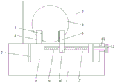
Fig. 1 is a side view of the present invention.
Fig. 2 is a top view of the present invention.
Fig. 3 is a schematic structural view of the gear and the connecting plate of the present invention.
Reference numbers in the figures: the grinding machine comprises a base 1, a grinding machine 2, a grinding disc 3, a non-slip mat 4, a fixing plate 5, a movable plate 6, a mounting groove 7, a movable seat 8, a threaded column 9, a movable block 10, a connecting groove 11, a rotating disc 12, a connecting plate 13, a gear 14, a rotating shaft 15, an adjusting column 16, a sliding groove 17, a limiting groove 18 and a limiting block 19.
Detailed Description
The technical solutions in the embodiments of the present invention will be described clearly and completely with reference to the accompanying drawings in the embodiments of the present invention, and it is obvious that the described embodiments are only some embodiments of the present invention, not all embodiments.
Referring to fig. 1-3, a polishing device for plastic pipe ports comprises a base 1 and a movable seat 8, wherein the top of the base 1 is provided with a mounting groove 7, the movable seat 8 is positioned inside the mounting groove 7, the top of the movable seat 8 is fixed with a fixed plate 5, the top of the movable seat 8 is provided with a sliding groove 17, the sliding groove 17 is rotatably connected with a threaded column 9, the threaded column 9 is externally and threadedly connected with a movable block 10, one end of the movable block 10 extends to the outside of the sliding groove 17, the movable block 10 is fixed with a movable plate 6 at one end positioned outside the sliding groove 17, a connecting plate 13 is fixed at the bottom of one side of the movable seat 8, the top of the connecting plate 13 is provided with a tooth socket, the top of the connecting plate 13 is engaged with a gear 14, one side of the gear 14 is fixed with a rotating shaft 15, one end of the rotating shaft 15 extends to the outside of the base 1 through the base, connecting groove 11 has been seted up to one side that base 1 was equipped with pivot 15, and the one end of screw thread post 9 runs through connecting groove 11 and extends to base 1's outside, and the one end that screw thread post 9 is located base 1 outside is fixed with carousel 12, and base 1's top is fixed with polisher 2, and polisher 2 is located one side of mounting groove 7, and polisher 2 includes polishing dish 3.
In this embodiment, remove the base of seat 8 and mounting groove 7 and contact mutually, one side of removing seat 8 is fixed with spacing piece 19, spacing groove 18 has been seted up to one side of mounting groove 7, the one end of spacing piece 19 extends to the inside of spacing groove 18, movable plate 6 cooperatees with fixed plate 5, one side that movable plate 6 and fixed plate 5 are close to mutually all is fixed with slipmat 4, slipmat 4 adopts the rubber preparation, the surface of slipmat 4 is equipped with anti-skidding line, movable block 10 and spout 17 are the rectangle structure, the both sides outer wall of movable block 10 contacts with the both sides inner wall of spout 17.
In the description of the present invention, it is to be understood that the terms "center", "longitudinal", "lateral", "length", "width", "thickness", "upper", "lower", "front", "rear", "left", "right", "vertical", "horizontal", "top", "bottom", "inner", "outer", "clockwise", "counterclockwise", and the like indicate orientations or positional relationships based on the orientations or positional relationships shown in the drawings, and are only for convenience of description and to simplify the description, but do not indicate or imply that the device or element referred to must have a particular orientation, be constructed and operated in a particular orientation, and therefore should not be construed as limiting the present invention.
Furthermore, the terms "first", "second" and "first" are used for descriptive purposes only and are not to be construed as indicating or implying relative importance or implicitly indicating the number of technical features indicated. Thus, a feature defined as "first" or "second" may explicitly or implicitly include one or more of that feature. In the description of the present invention, "a plurality" means two or more unless specifically limited otherwise.
The working principle is as follows: place tubular product between fixed plate 5 and movable plate 6, then rotate carousel 12, carousel 12 drives screw thread post 9 and rotates, screw thread post 9 and then drives the movable block 10 and remove, thereby make movable plate 6 be close to fixed plate 5, it is tight with tubular product clamp to make movable plate 6, then stall carousel 12, start polisher 2 after that, then anticlockwise stir the regulation post, gear 14 rotates and then drives connecting plate 13 and remove, connecting plate 13 drives and removes seat 8 and remove, make the port of tubular product be close to polishing dish 3, the port and the polishing dish 3 contact of tubular product, finally realize the purpose of polishing.
The above, only be the concrete implementation of the preferred embodiment of the present invention, but the protection scope of the present invention is not limited thereto, and any person skilled in the art is in the technical scope of the present invention, according to the technical solution of the present invention and the utility model, the concept of which is equivalent to replace or change, should be covered within the protection scope of the present invention.
Claims (5)
1. A polishing device for plastic pipe ports comprises a base (1) and a moving seat (8), and is characterized in that a mounting groove (7) is formed in the top of the base (1), the moving seat (8) is located inside the mounting groove (7), a fixing plate (5) is fixed to the top of the moving seat (8), a sliding groove (17) is formed in the top of the moving seat (8), a threaded column (9) is rotatably connected to the inside of the sliding groove (17), a moving block (10) is connected to the outer portion of the threaded column (9) in a threaded manner, one end of the moving block (10) extends to the outer portion of the sliding groove (17), a moving plate (6) is fixed to one end, located outside the sliding groove (17), of the moving seat (8), a connecting plate (13) is fixed to the bottom of one side, a tooth groove is formed in the top of the connecting plate (13), a gear (14) is meshed with the top of the connecting plate (13), the one end of pivot (15) runs through the outside that base (1) extended to base (1), pivot (15) are rotated with base (1) and are connected, the one end that pivot (15) are located base (1) outside is fixed with regulation post (16), spread groove (11) have been seted up to one side that base (1) was equipped with pivot (15), the one end of screw thread post (9) runs through the outside that spread groove (11) extended to base (1), and screw thread post (9) are located the one end of base (1) outside and are fixed with carousel (12), the top of base (1) is fixed with polisher (2), polisher (2) are located the one side of mounting groove (7), polisher (2) are including polishing dish (3).
2. The plastic pipe port polishing device according to claim 1, wherein the movable seat (8) is in contact with the bottom of the mounting groove (7), a limiting block (19) is fixed on one side of the movable seat (8), a limiting groove (18) is formed in one side of the mounting groove (7), and one end of the limiting block (19) extends into the limiting groove (18).
3. The plastic pipe end polishing device according to claim 1, wherein the movable plate (6) is matched with the fixed plate (5), and the non-slip mat (4) is fixed on one side of the movable plate (6) close to the fixed plate (5).
4. The plastic pipe port polishing device according to claim 3, wherein the non-slip mat (4) is made of rubber, and the surface of the non-slip mat (4) is provided with non-slip lines.
5. The plastic pipe port polishing device as claimed in claim 1, wherein the moving block (10) and the sliding groove (17) are both rectangular structures, and two side outer walls of the moving block (10) are in contact with two side inner walls of the sliding groove (17).
Priority Applications (1)
| Application Number | Priority Date | Filing Date | Title |
|---|---|---|---|
| CN201920814109.7U CN210113014U (en) | 2019-05-31 | 2019-05-31 | Plastic pipe port polishing device |
Applications Claiming Priority (1)
| Application Number | Priority Date | Filing Date | Title |
|---|---|---|---|
| CN201920814109.7U CN210113014U (en) | 2019-05-31 | 2019-05-31 | Plastic pipe port polishing device |
Publications (1)
| Publication Number | Publication Date |
|---|---|
| CN210113014U true CN210113014U (en) | 2020-02-25 |
Family
ID=69579029
Family Applications (1)
| Application Number | Title | Priority Date | Filing Date |
|---|---|---|---|
| CN201920814109.7U Active CN210113014U (en) | 2019-05-31 | 2019-05-31 | Plastic pipe port polishing device |
Country Status (1)
| Country | Link |
|---|---|
| CN (1) | CN210113014U (en) |
Cited By (2)
| Publication number | Priority date | Publication date | Assignee | Title |
|---|---|---|---|---|
| CN112123198A (en) * | 2020-09-11 | 2020-12-25 | 安徽誉林汽车部件有限公司 | Automobile connecting rod bush grinding device |
| CN115284129A (en) * | 2022-08-12 | 2022-11-04 | 德润杰(山东)纺织科技有限公司 | Efficient polishing equipment for machining core rod |
-
2019
- 2019-05-31 CN CN201920814109.7U patent/CN210113014U/en active Active
Cited By (2)
| Publication number | Priority date | Publication date | Assignee | Title |
|---|---|---|---|---|
| CN112123198A (en) * | 2020-09-11 | 2020-12-25 | 安徽誉林汽车部件有限公司 | Automobile connecting rod bush grinding device |
| CN115284129A (en) * | 2022-08-12 | 2022-11-04 | 德润杰(山东)纺织科技有限公司 | Efficient polishing equipment for machining core rod |
Similar Documents
| Publication | Publication Date | Title |
|---|---|---|
| CN210113014U (en) | Plastic pipe port polishing device | |
| CN210476432U (en) | Brake block arc chamfer processingequipment | |
| CN210060643U (en) | Grinding device is used in production of no aldehyde plywood of soybean | |
| CN217475590U (en) | Surface polishing device for formed false tooth | |
| CN214292392U (en) | Positioning mechanism of burr polisher | |
| CN215748301U (en) | Burr removing device for glass cutting | |
| CN211355681U (en) | Haemostat for clinical operation of department of general surgery | |
| CN212346563U (en) | Ultrasonic department's inspection bed with adjustable back of body pad | |
| CN211136649U (en) | A grinding device for furniture production | |
| CN107498403A (en) | A kind of bearing lapping device to reduce friction | |
| CN112472960A (en) | Anesthesia machine screwed pipe adjusting device is used in department of anesthesia operation | |
| CN218801387U (en) | Polishing device for radiator of plug-in sheet type printer | |
| CN110614599A (en) | Positioning mechanism for hardware processing | |
| CN111975533A (en) | Edge grinding device for producing tablet computer screen glass and production method thereof | |
| CN217255154U (en) | Edging device of kitchen stainless steel basin production usefulness | |
| CN219542616U (en) | Thermos cup mouth-benefiting machine | |
| CN216776035U (en) | Poria cocos peeling device for poria cocos processing | |
| CN218697375U (en) | Pottery surface finish device | |
| CN214351313U (en) | Inner cavity polishing device for chromium plating of crystallizer copper pipe | |
| CN210582684U (en) | Crown remover device | |
| CN217167878U (en) | Edging device is used in plastic products production | |
| CN216456235U (en) | External drainage device convenient to it is fixed | |
| CN218390502U (en) | Display device for electric power marketing digital equipment | |
| CN211136572U (en) | Deburring device for brake disc machining | |
| CN218051641U (en) | Cutting device of high wear-resisting metal product |
Legal Events
| Date | Code | Title | Description |
|---|---|---|---|
| GR01 | Patent grant | ||
| GR01 | Patent grant |