CN210111107U - Electric connector assembly and electronic equipment - Google Patents
Electric connector assembly and electronic equipment Download PDFInfo
- Publication number
- CN210111107U CN210111107U CN201921483227.0U CN201921483227U CN210111107U CN 210111107 U CN210111107 U CN 210111107U CN 201921483227 U CN201921483227 U CN 201921483227U CN 210111107 U CN210111107 U CN 210111107U
- Authority
- CN
- China
- Prior art keywords
- plate
- insulator
- cover
- fixed
- insulating cover
- Prior art date
- Legal status (The legal status is an assumption and is not a legal conclusion. Google has not performed a legal analysis and makes no representation as to the accuracy of the status listed.)
- Active
Links
Images


Abstract
The electric connector assembly comprises at least two connector modules, an outer insulating cover and an outer metal cover, wherein each connector module comprises an insulator, a plurality of conductive terminals fixed with the insulator and a metal shell surrounding the insulator, the insulator comprises a base and a cantilever-shaped tongue plate which extends forwards from the base, the insulator and the metal shell jointly enclose a plugging space which is matched and butted with the matching side connector, and a plugging port is formed in front of the insulator, the outer insulating cover and the outer metal cover form abdication corresponding to the position of the plug interface, the outer insulating cover is penetrated and formed with at least two containing holes correspondingly containing the connector module along the front and back direction, the outer insulating cover is sleeved on the peripheries of the at least two connector modules, the outer metal cover is sleeved on the periphery of the outer insulating cover, and the outer metal cover and the metal shell are fixed through welding.
Description
[ technical field ] A method for producing a semiconductor device
The present application relates to the field of electrical connector assemblies and electronic devices.
[ background of the invention ]
11 th month 8 2014, the USB association has announced a novel electric connector, and its plug connector can positive and negative two directions insert corresponding socket connector, and this socket connector can transmit USB2.0 and USB3.1 signal, and this connector name is USB Type C connector. According to the news reported in the industry, the electric connector has a great development potential, and various connector manufacturers are actively developing in cooperation with system manufacturers.
However, the appearance, structure, terminal contact manner, number of terminals, distance between terminals (Pitch), and Pin Assignment of terminals (Pin Assignment) of the latest USB Type-C electrical connector are different from those of the current USB electrical connector. The USB Type-C socket electric connector comprises two rows of flat plate terminals which are arranged on the rubber core and are symmetrical up and down, and the rubber core is externally covered with structures such as an outer iron shell. The rubber core of the general USB Type-C socket electric connector is formed by assembling, combining and injection molding a plurality of rubber bodies, and each rubber body is respectively combined with a row of upper-row flat terminals and a row of lower-row flat terminals.
However, as the use of the USB Type-C electrical connector becomes more widespread, in some devices, a plurality of USB Type-C receptacle electrical connectors need to be installed. A common operation method in the prior art is to fix a plurality of independent USB Type-C socket electrical connectors to the electronic device, respectively, so that the assembly process is complicated. In some fields, there is a design method that a plurality of receptacle electrical connectors are stacked left and right or stacked up and down to form a whole, however, the overall structure of the stacked design is generally complicated, and some undesirable effects caused by the stacked design exist, such as: poor grounding performance, poor shielding performance, complex assembly process, poor stability of the whole structure and the like.
Therefore, there is a need to provide a new electrical connector assembly and an electronic device to overcome the above-mentioned drawbacks.
[ Utility model ] content
An object of the present invention is to provide a novel electrical connector assembly and an electronic device, wherein the electrical connector assembly has good grounding performance, good shielding performance, simple assembly process, and good stability of the overall structure.
In order to achieve the above purpose, the present application is implemented by the following technical solutions:
an electric connector assembly is used for being fixed on an electronic device and being electrically connected with an internal circuit of the electronic device and is used for being matched and butted with a matching side connector, the electric connector assembly comprises at least two connector modules, an outer insulating cover and an outer metal cover, each connector module comprises an insulator, a plurality of conductive terminals fixed with the insulator and a metal shell surrounding the periphery of the insulator, the insulator comprises a base part and a cantilever-shaped tongue plate extending forwards from the base part, each conductive terminal comprises a contact part fixed on the tongue plate and at least partially exposed out of the tongue plate, a fixed part connected with the contact part and fixed in the base part and a butting part connected with the fixed part and extending outwards out of the insulator, the insulator and the metal shell jointly surround a plugging space matched and butted with the matching side connector and form a plugging port in front, the outer insulating cover and the outer metal cover correspond to the socket positions to form yielding, the outer insulating cover penetrates along the front-back direction to form at least two accommodating holes corresponding to the accommodating connector modules, the outer insulating cover is sleeved on the peripheries of the at least two connector modules, the outer metal cover is sleeved on the periphery of the outer insulating cover, and the outer metal cover and the metal shell are fixed through welding.
Further, the at least two connector modules are respectively independent and arranged along the left and right direction.
Further, the metal shell comprises a barrel-shaped part and a rear cover part, the barrel-shaped part is arranged at the periphery of the tongue plate in a surrounding mode, the rear end edge of the barrel-shaped part is connected with the rear end edge of the barrel-shaped part and arranged at the periphery of the base part in a surrounding mode, the outer insulating cover is arranged at the rear end position of the upper portion of the metal shell and provided with a yielding notch, at least part of the metal shell is exposed out of the yielding notch, the outer metal cover is bent downwards corresponding to the yielding notch to form a fixing piece, and the fixing piece is attached to the corresponding position of.
Furthermore, the top of metal casing forms the fluting in back cover position end, the fluting becomes T shape to be formed with two buckle plates that extend in opposite directions, the buckle plate expose to the breach of stepping down and with the stationary blade passes through welded fastening.
Furthermore, at least two containing holes of the outer insulating cover are separated by a barrier wall, two sides of the rear end position of the barrier wall are provided with clamping grooves, protruding columns are correspondingly formed at two sides of the base of the insulator, the connector modules are respectively assembled and fixed in the containing holes of the outer insulating cover from back to front, and the clamping grooves are correspondingly fixed with the protruding columns in a clamping mode.
Further, the outer metal cover comprises a top plate, a front end plate formed by bending the front end edge of the top plate downwards, side plates formed by bending two sides of the front end plate backwards, a lower side plate formed by bending the lower side edge of the front end plate backwards, a clamping plate formed by bending two side edges of the top plate downwards, a rear end plate formed by bending the rear end edge of the top plate downwards, and a fixing plate formed by bending two sides of the rear end plate forwards, wherein the top plate is attached to the upper surface of the outer insulating cover, the front end plate is attached to the front end surface of the outer insulating cover, the side plates are attached to two side surfaces of the outer insulating cover, the lower side plate is correspondingly attached to the lower surface of the outer insulating cover, the rear end plate covers the rear end surfaces of the outer insulating cover and the connector module, the clamping plate is attached to the outer surfaces of the side plates, and the fixing plate is attached to the outer surfaces of the clamping plate.
Furthermore, the plurality of conductive terminals are arranged in two rows to form a first terminal group and a second terminal group, and the first terminal group and the second terminal group both comprise twelve conductive terminals and meet the arrangement standard of USB Type C.
Further, the insulator includes first insulator, second insulator and insulating base block, first insulator is fixed and forms first terminal module with a row of conductive terminal, second insulator forms second terminal module with another row of conductive terminal is fixed, first terminal module and second terminal module stack the equipment along upper and lower direction, insulating base block is fixed through integrated into one piece and first terminal module and second terminal module.
Further, still include the shield plate, the shield plate is located between two rows of conductive terminal, shield plate rear end edge both sides position is formed with flexible arm, flexible arm by outside the protruding insulator that stretches out of both sides of the basal portion of insulator, flexible arm and metal casing overlap joint, the shield plate extends along the full width of first terminal group and second terminal group, and extends on the full length of the contact site of each conductive terminal and fixed part.
In order to achieve the above purpose, the present application also discloses the following technical solutions:
an electronic device comprising an electrical connector assembly as claimed in any preceding claim.
Compared with the prior art, the method has the following beneficial effects:
this design is passed through, and outer insulating boot and outer metal covering are with a plurality of connector module integrations, with outer metal covering, metal casing and shield plate electric connection simultaneously, increase electric connector assembly's whole ground connection shielding effect, and the equipment between outer metal covering and the outer insulating boot is fixed firm for whole electric connector assembly has that ground connection performance is good, shielding performance is good, assembly process is simple, and overall structure stability advantage such as good.
[ description of the drawings ]
Fig. 1 is a perspective view of an electrical connector assembly of the present application;
fig. 2 is a perspective view of the electrical connector assembly of fig. 1 from another angle;
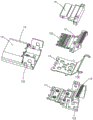
fig. 3 is a partial exploded perspective view of the electrical connector assembly of the present application, generally showing the outer metal shell, the outer insulating shell and the electrical connector in a separated perspective view;
fig. 4 is an exploded perspective view of the electrical connector assembly of fig. 3 from another perspective;
fig. 5 is a partial exploded perspective view of the electrical connector of the present application, showing primarily the perspective view of the metal shell separated from the insulator;
fig. 6 is a partially exploded perspective view of the electrical connector of the present application, generally showing the metal shell and dielectric block in perspective with the terminal module separated;
fig. 7 is a further exploded perspective view of the electrical connector of fig. 6;
fig. 8 is a further exploded perspective view of the electrical connector of fig. 7 from another angle;
fig. 9 is a perspective view of the electrical connector of fig. 8 from another angle;
[ detailed description ] embodiments
It should be noted that the embodiments and features of the embodiments in the application may be combined with each other without conflict. The following detailed description will refer to the accompanying drawings in conjunction with embodiments.
Throughout the description of the application, it is to be noted that, unless expressly stated or limited otherwise, the terms "mounted," "connected," and "connected" are to be construed broadly, e.g., as meaning either a fixed connection, a removable connection, or an integral connection; can be mechanically or electrically connected; they may be connected directly or indirectly through intervening media, or they may be interconnected between two elements. The specific meaning of the above terms in the application can be understood in a specific context by those of ordinary skill in the art.
In the description of the application, it is to be understood that the terms "comprises" and "comprising," and any variations thereof, as used herein, are intended to cover a non-exclusive inclusion, such that a process, method, system, article, or apparatus that comprises a list of steps or elements is not necessarily limited to those steps or elements expressly listed, but may include other steps or elements not expressly listed or inherent to such process, method, article, or apparatus.
In addition, for the sake of accuracy of the description of the present application, the entire text referring to the directions refers to fig. 1, wherein the X-axis extending direction is the left-right direction, the Y-axis extending direction is the front-back direction (wherein the Y-axis forward direction is the back), and the Z-axis extending direction is the up-down direction (wherein the Z-axis forward direction is the up).
Referring to fig. 1 to 9, the electrical connector assembly of the present application is used to be fixed to an electronic device and electrically connected to an internal circuit of the electronic device, and is used to mate with a mating connector to realize data transmission (including but not limited to signals, power, etc.) between the electronic device and the outside.
Referring to fig. 1 to 4, the electrical connector assembly includes a connector module 1, an outer insulating housing 2, and an outer metal housing 3. In this application, connector module 1 is provided with threely, and is three connector module 1 is independent respectively and arranges the setting along left right direction, 2 covers of outer insulating boot are located three connector module 1's periphery, 3 covers of outer metal covering are located the periphery of outer insulating boot 2.
Referring to fig. 5 to 9, each of the connector modules 1 in the present application is actually a USB Type C socket connector (USB interface), and includes a first terminal module 11, a second terminal module 12, a shielding member 13, an insulating base block 14, and a metal shell 15. The first terminal module 11 includes a first insulating body 111 and a first terminal set 112 integrally fixed with the first insulating body 111; the second terminal module 12 includes a second insulating housing 121 and a second terminal set 122 integrally fixed to the second insulating housing 121. Each of the first terminal set 112 and the second terminal set 122 includes twelve conductive terminals 110 arranged in a left-right direction (the arrangement is in accordance with the USB Type C standard). The shield 13 is formed by stamping and bending a metal plate. The first terminal module 11, the shielding plate 13, and the second terminal module 12 are stacked, assembled, and fixed in the vertical direction. The shield plate 13 is sandwiched between the first terminal module 11 and the second terminal module 12. Each of the first terminal set 112 and the second terminal set 122 includes a power terminal (not labeled), a ground terminal (not labeled) and a signal terminal (not labeled).
The insulating base block 14 integrally fixes the first terminal module 11, the shielding plate 13, and the second terminal module 12, which are stacked and assembled together, to one body. The insulating base block 14, the first insulating body 111 and the second insulating body 121 together form an insulator (not labeled). The insulator defines a base 101 and a tongue 102 formed by the base 101 extending forwardly. The tongue plate 102 forms an upper surface 1021 and a lower surface 1022 which are parallel to each other.
Each of the conductive terminals 110 of the first terminal set 112 includes a contact portion (not labeled) extending in a front-rear direction, a fixing portion (not labeled) integrally connected with the contact portion (not labeled), and a mating portion (not labeled) for electrically connecting with a mating circuit board. The contact portion is fixed in the tongue plate 102 and exposed to the upper surface of the tongue plate 102. The fixing part is embedded in the insulator. The abutment projects downwardly from the base 101 of the insulator beyond the insulator.
Each of the conductive terminals 110 of the second terminal set 122 includes a contact portion (not labeled) extending in a front-rear direction, a fixing portion (not labeled) integrally connected with the contact portion (not labeled), and a mating portion (not labeled). The contact portion is fixed in the tongue plate 102 and exposed to the lower surface of the tongue plate 102. The fixing part is embedded in the insulator. The abutment projects downwardly from the base 101 of the insulator beyond the insulator. The mating portions of the first terminal group 112 are arranged in a row in the left-right direction, and the mating portions of the second terminal group 122 are arranged in a row in the left-right direction and in front of the mating portions of the first terminal group 112 in the row.
The shielding plate 13 is located between the row of the first terminal set 112 and the row of the second terminal set 122, and the shielding plate 13 extends along the full width of the first terminal set 112 and the second terminal set 122 and extends along the full length of the contact portion and the fixing portion of each conductive terminal 110, so as to ensure a good shielding effect. In the present application, only a local position on the shielding plate 13 is penetrated with an assembly hole for assembly (for yielding when the first terminal module 11, the shielding plate 13 and the second terminal module 12 are stacked and assembled in the up-down direction). In some embodiments, the shield plate 13 may be designed to short to each ground terminal.
Referring to fig. 2 to 4 and 7 to 8, in the present application, the elastic arms 130 are bent and extended at two sides of the rear end edge of the shielding plate 13. The elastic arms 130 protrude from both sides of the base 101 of the insulator to the outside of the insulator. Each of the elastic arms 130 extends from the front to the rear and is elastically deformable in the width direction.
The metal shell 15 is formed by stamping and bending a metal plate, and includes a barrel portion 151 surrounding the outer periphery of the tongue plate 102, and a rear cover portion 152 extending rearward from the rear end edge of the barrel portion 151 and extending downward from both sides. The rear cover portion 152 is substantially n-shaped, and the rear cover portion 152 covers the upper surface and both side surfaces of the base portion 101 of the insulator. The metal shell 15 and the insulator together enclose a plug space 100 and form a plug interface 1001 in front. The plug space 100 is used for mating with a mating-side connector (plug connector). The elastic arm 130 of the shielding plate 13 is elastically abutted against the inner surface of the rear cover 152.
The upper surface of the metal shell 15 is formed with a T-shaped slot 150 at the end of the rear cover portion 152, and two buckling plates 153 extending towards each other. A locking hole 1530 is formed through each locking plate 153. The snap hole 1530 is matingly engaged with a correspondingly formed protrusion 1010 on the upper surface of the base 101. The T-shaped slot 150 is designed to allow the end of the latch plate 153 to elastically deform in the vertical direction, thereby facilitating the assembly of the metal shell 15 to the insulator.
Referring to fig. 3, 4, and 6 to 9, two sides of the base 101 of the insulator respectively protrude outward to form protruding columns 103. The rear end edge positions of the two sides of the metal shell 15 are backwards provided with yielding openings 154. The posts 103 pass through the position-giving openings 154 along the left-right direction and protrude out of the metal shell 15 and correspondingly clamp with the outer insulating cover 2.
Referring to fig. 1 to 5, the outer insulating cover 2 is formed by injection molding of a plastic material, the outer insulating cover 2 penetrates along a front-back direction to form three receiving holes 21, the three receiving holes 21 are arranged in a left-right direction, and the middle of the three receiving holes are separated by a barrier wall 22. The two sides of the rear end of the blocking wall 22 are provided with fastening grooves 221, the connector modules are respectively assembled and fixed into the accommodating holes 21 from back to front, and the fastening grooves 221 are correspondingly fastened and fixed with the studs 103. The outer insulating cover 2 forms an abdicating notch 104 above the rear end of each accommodating hole 21, and the fastening plate 153 is at least partially exposed upwards to the abdicating notch 104. An assembly groove 105 is concavely formed at the front end position of the lower surface of the outer insulating cover 2, a buckling block 106 is formed by extending downwards in the assembly groove 105, and the buckling block 106 is buckled with a corresponding structure of the outer metal cover 3.
Referring to fig. 1 to 5, the outer metal cover 3 is formed by bending a metal plate by pressing, and includes a flat top plate 31, a front end plate 32 formed by bending a front end edge of the top plate 31 downward, a side plate 33 formed by bending both sides of the front end plate 32 rearward, a lower side plate 34 formed by bending a lower side edge of the front end plate 32 rearward, a latch plate 35 formed by bending both side edges of the top plate 31 downward, a rear end plate 36 formed by bending a rear end edge of the top plate 31 downward, and a fixing plate 37 formed by bending both sides of the rear end plate 36 forward. The front plate 32 has a relief hole 320 corresponding to the receiving hole 21 and the insertion port 1001.
The outer metal cover 3 is fixed to the outer periphery of the outer insulating cover 2 by assembly. The top plate 31 is attached to the upper surface of the outer insulating cover 2. The front end plate 32 is attached to the front end surface of the outer insulating cover 2. The side plates 33 are attached to both side surfaces of the outer insulating cover 2. The lower side plate 34 is correspondingly attached to the assembly groove 105 of the outer insulating cover 2 and is fastened and fixed with the fastening block 106. The rear end plate 36 covers the rear end surfaces of the outer insulating cover 2 and the connector module 1. The fastening plate 35 is attached to the outer surface of the side plate 33. The fixing plate 37 is attached to the outer surface of the latch plate 35.
In the present application, the fastening plate 35 and the side plate 33, and the fixing plate 37 and the fastening plate are fixed by fixing mechanisms, which may be a fitting structure of a projection and a groove (one of them forms a projection, and the other forms a groove or a hole for fitting the fastener), or may be fixed by welding.
Referring to fig. 1 to 5, the rear end of the top plate 31 of the outer metal cover 3 is torn at a position corresponding to the relief notch 104 and is bent downward to form a fixing piece 311. The fixing piece 311 is formed in a stepped shape with the top plate 31. The fixing piece 311 correspondingly passes through the abdicating notch 104 and is attached to the upper surface of the fastening plate 153 of the metal shell 15, and the fixing piece 311 and the fastening plate 153 are fixed by welding. In the present application, the lower side edges of the side plates 33 and the rear end plate 36 are each formed with a fillet portion 38 extending downward for welding and fixing with a mating circuit board (not shown).
The electric connector assembly is used for an electronic device, and the electronic device can be a smart phone, a mobile computer, a tablet computer, a desktop computer, an electronic device system for an automobile, a television or the like needing to use the electric connector.
This design is passed through, and outer insulating boot 2 and outer metallic cover 3 integrate a plurality of connector modules, with outer metallic cover 3, metal casing 15 and shield plate 13 electric connection simultaneously, increase the whole ground connection shielding effect of electric connector subassembly. The outer metal cover 3 covers and shields all the areas of the connector module except the mating area of the conductive terminals 110 and the area of the socket 1001. The outer metal cover 3 and the outer insulating cover 2 are firmly assembled and fixed. The whole electric connector assembly has the advantages of good grounding performance, good shielding performance, simple assembly process, good stability of the whole structure and the like.
The above description is only a part of the embodiments of the present application, and not all embodiments, and any equivalent changes to the technical solutions of the present application, which are made by those skilled in the art through reading the present specification, are covered by the claims of the present application.
Claims (10)
1. An electrical connector assembly for securing to an electronic device and electrically connecting to internal circuitry of the electronic device for mating with a mating connector, comprising: the electric connector assembly comprises at least two connector modules, an outer insulating cover and an outer metal cover, wherein each connector module comprises an insulator, a plurality of conductive terminals fixed with the insulator and a metal shell arranged around the periphery of the insulator, the insulator comprises a base and a cantilever-shaped tongue plate extending forwards from the base, each conductive terminal comprises a contact part fixed on the tongue plate and at least partially exposed out of the tongue plate, a fixed part connected with the contact part and fixed in the base and a butt joint part connected with the fixed part and extending outwards out of the insulator, the insulator and the metal shell jointly enclose a splicing space matched and butted with a matched side connector and form a splicing port in front, the outer insulating cover and the outer metal cover form a yielding position corresponding to the splicing port, and the outer insulating cover penetrates in the front-back direction to form at least two accommodating holes correspondingly accommodating the connector modules, the outer insulating cover is sleeved on the peripheries of the at least two connector modules, the outer metal cover is sleeved on the periphery of the outer insulating cover, and the outer metal cover and the metal shell are fixed through welding.
2. The electrical connector assembly of claim 1, wherein: the at least two connector modules are respectively independent and arranged along the left and right direction.
3. The electrical connector assembly of claim 1, wherein: the metal shell comprises a barrel-shaped part and a rear cover part, wherein the barrel-shaped part is arranged at the periphery of the tongue plate in a surrounding mode, the rear end edge of the barrel-shaped part is connected with the rear end edge of the base part in a surrounding mode, the rear cover part is arranged on the rear end of the upper portion of the metal shell in a surrounding mode, at least part of the metal shell is exposed to the yielding notch, the outer metal cover corresponds to the yielding notch and is bent downwards to form a fixing piece, and the fixing piece is attached to the corresponding position of the metal shell in a corresponding mode and is fixed through welding.
4. The electrical connector assembly of claim 3, wherein: the top of metal casing forms the fluting in back cover position end, the fluting becomes T shape to be formed with two buckle plates of opposite extension, the buckle plate expose to the breach of stepping down and with the stationary blade passes through welded fastening.
5. The electrical connector assembly of claim 2, wherein: the connector module is characterized in that at least two accommodating holes of the outer insulating cover are separated by a barrier wall, two sides of the rear end position of the barrier wall are provided with clamping grooves, protruding columns are correspondingly formed at two sides of the base of the insulator, the connector module is respectively assembled and fixed in the accommodating holes of the outer insulating cover from back to front, and the clamping grooves are correspondingly fixed with the protruding columns in a clamping mode.
6. The electrical connector assembly of claim 2, wherein: the outer metal cover comprises a top plate, a front end plate formed by bending the front end edge of the top plate downwards, side plates formed by bending two sides of the front end plate backwards, a lower side plate formed by bending the lower side edge of the front end plate backwards, clamping plates formed by bending two side edges of the top plate downwards, a rear end plate formed by bending the rear end edge of the top plate downwards, and a fixing plate formed by bending two sides of the rear end plate forwards, wherein the top plate is attached to the upper surface of the outer insulating cover, the front end plate is attached to the front end surface of the outer insulating cover, the side plates are attached to two side surfaces of the outer insulating cover, the lower side plate is correspondingly attached to the lower surface of the outer insulating cover, the rear end plate covers the rear end surfaces of the outer insulating cover and the connector module, the clamping plates are attached to the outer surfaces of the side plates, and the fixing plate is attached to the outer surfaces of the clamping plates.
7. The electrical connector assembly of claim 1, wherein: the plurality of conductive terminals are arranged in two rows to form a first terminal group and a second terminal group, and the first terminal group and the second terminal group respectively comprise twelve conductive terminals and accord with the arrangement standard of USB Type C.
8. The electrical connector assembly of claim 7, wherein: the insulator comprises a first insulating body, a second insulating body and an insulating base block, wherein the first insulating body is fixed with one row of conductive terminals and forms a first terminal module, the second insulating body is fixed with the other row of conductive terminals and forms a second terminal module, the first terminal module and the second terminal module are stacked and assembled in the vertical direction, and the insulating base block is fixed with the first terminal module and the second terminal module through integral forming.
9. The electrical connector assembly of claim 6, wherein: still include the shield plate, the shield plate is located between two rows of conductive terminal, shield plate rear end edge both sides position is formed with flexible arm, flexible arm by outside the protruding insulator that stretches out of both sides of the basal portion of insulator, flexible arm and metal casing overlap joint, the shield plate extends along first terminal group and second terminal group's full width, and extends on the full length of the contact site of each conductive terminal and fixed part.
10. An electronic device, characterized in that: comprising an electrical connector assembly according to any one of claims 1 to 9.
Priority Applications (1)
| Application Number | Priority Date | Filing Date | Title |
|---|---|---|---|
| CN201921483227.0U CN210111107U (en) | 2019-09-07 | 2019-09-07 | Electric connector assembly and electronic equipment |
Applications Claiming Priority (1)
| Application Number | Priority Date | Filing Date | Title |
|---|---|---|---|
| CN201921483227.0U CN210111107U (en) | 2019-09-07 | 2019-09-07 | Electric connector assembly and electronic equipment |
Publications (1)
| Publication Number | Publication Date |
|---|---|
| CN210111107U true CN210111107U (en) | 2020-02-21 |
Family
ID=69532002
Family Applications (1)
| Application Number | Title | Priority Date | Filing Date |
|---|---|---|---|
| CN201921483227.0U Active CN210111107U (en) | 2019-09-07 | 2019-09-07 | Electric connector assembly and electronic equipment |
Country Status (1)
| Country | Link |
|---|---|
| CN (1) | CN210111107U (en) |
Cited By (2)
| Publication number | Priority date | Publication date | Assignee | Title |
|---|---|---|---|---|
| CN110444945A (en) * | 2019-09-07 | 2019-11-12 | 昆山嘉华电子有限公司 | Electric coupler component and electronic equipment |
| CN113783004A (en) * | 2021-08-26 | 2021-12-10 | 歌尔光学科技有限公司 | Board-to-board connector and electronic equipment |
-
2019
- 2019-09-07 CN CN201921483227.0U patent/CN210111107U/en active Active
Cited By (3)
| Publication number | Priority date | Publication date | Assignee | Title |
|---|---|---|---|---|
| CN110444945A (en) * | 2019-09-07 | 2019-11-12 | 昆山嘉华电子有限公司 | Electric coupler component and electronic equipment |
| CN113783004A (en) * | 2021-08-26 | 2021-12-10 | 歌尔光学科技有限公司 | Board-to-board connector and electronic equipment |
| CN113783004B (en) * | 2021-08-26 | 2024-04-02 | 歌尔科技有限公司 | Board-to-board connector and electronic equipment |
Similar Documents
| Publication | Publication Date | Title |
|---|---|---|
| US11715907B2 (en) | Electrical connector with fool-proof function | |
| CN104505642B (en) | Plug electric connector | |
| TWI548158B (en) | Electrical receptacle connector | |
| US9954319B2 (en) | Electrical connector assembly | |
| US7390219B2 (en) | Electrical connector having improved outer shield | |
| US20170033506A1 (en) | Electrical connector having good anti-emi perfprmance | |
| US8021187B2 (en) | Electric connector | |
| US20010049227A1 (en) | Electrical connector assembly with improved shielding structure | |
| US20180294602A1 (en) | Connector assembly with an improved latch member having a shorter length | |
| CN107039807B (en) | Electric connector | |
| CN110867700A (en) | Electrical connector | |
| CN210111107U (en) | Electric connector assembly and electronic equipment | |
| US8696380B2 (en) | Cable assembly with removable fastening module | |
| CN116526192A (en) | Electric connector | |
| US6863546B2 (en) | Cable connector assembly having positioning structure | |
| US20140206231A1 (en) | Electrical connector with improved terminals | |
| CN110444945A (en) | Electric coupler component and electronic equipment | |
| CN114914749A (en) | Electrical connector, method of manufacture and connector assembly | |
| CN109256643B (en) | High-speed connector module | |
| CN209981537U (en) | Electrical connector | |
| CN109256634B (en) | High-speed connector module and manufacturing method thereof | |
| CN210779301U (en) | Electrical connector | |
| CN215989558U (en) | Electrical connection device | |
| CN218300367U (en) | Power supply connector | |
| CN214280341U (en) | Electrical connector |
Legal Events
| Date | Code | Title | Description |
|---|---|---|---|
| GR01 | Patent grant | ||
| GR01 | Patent grant |