CN210097465U - Printing and dyeing raw materials compounding device - Google Patents
Printing and dyeing raw materials compounding device Download PDFInfo
- Publication number
- CN210097465U CN210097465U CN201920335722.0U CN201920335722U CN210097465U CN 210097465 U CN210097465 U CN 210097465U CN 201920335722 U CN201920335722 U CN 201920335722U CN 210097465 U CN210097465 U CN 210097465U
- Authority
- CN
- China
- Prior art keywords
- printing
- shaft
- mixing
- outside
- base
- Prior art date
- Legal status (The legal status is an assumption and is not a legal conclusion. Google has not performed a legal analysis and makes no representation as to the accuracy of the status listed.)
- Active
Links
Images
Abstract
The utility model belongs to the technical field of the printing and dyeing technique and specifically relates to a printing and dyeing raw materials compounding device, the on-line screen storage device comprises a base, the upper end left side of base is connected with L type support, the upper end right side of base is equipped with the compounding case, the right side upper portion and the lower part of compounding case communicate respectively has inlet pipe and discharging pipe, just be equipped with switch valve on the discharging pipe, the inner chamber top of compounding case is rotated and is connected with the (mixing) shaft, the inner chamber lower part of compounding case is rotated and is connected with the axis of rotation, the left end of axis of rotation runs through the compounding case and has fixedly cup jointed the gear, gear motor's output shaft is connected with the upper end of (mixing) shaft, two the transmission is connected. Compared with the prior art, the utility model has the advantages of reasonable design, it is convenient to use, has powerful practicality and functionality, facilitates the use more.
Description
Technical Field
The utility model relates to a printing and dyeing technical field especially relates to a printing and dyeing raw materials compounding device.
Background
Printing and dyeing are the synthesis of the physical and chemical treatment processes of textile fabrics. The physical or chemical change between the printing and dyeing agent (dye) and the fiber can make the textile have certain color and luster and glossiness, and can improve the aesthetic degree of the textile.
Before printing, a plurality of printing raw materials need to be mixed to obtain a proper printing dye. The mode that the printing and dyeing raw materials mixes at present adopts mixing arrangement to stir the mixing mostly, but current mixing arrangement mostly is simple drives the (mixing) shaft through the motor and rotates and stir, stirring mode is single, the unable abundant mixing of multiple raw materials, it is relatively poor to mix the effect, and the (mixing) shaft drives mixed liquid unidirectional rotation at the in-process of stirring in addition, forms the sediment in the bottom of compounding case easily, there is the stirring dead angle, can produce very big influence, inconvenient use to the quality of ink-jet printing agent.
SUMMERY OF THE UTILITY MODEL
The utility model aims at solving the shortcoming that exists among the prior art, and the printing and dyeing raw materials compounding device that proposes for the printing and dyeing raw materials mixes more evenly, facilitates the use more.
In order to achieve the above purpose, the utility model adopts the following technical scheme:
a printing and dyeing raw material mixing device is designed, and comprises a base, wherein an L-shaped support is connected to the left side of the upper end of the base, a mixing box is arranged on the right side of the upper end of the base, the upper portion and the lower portion of the right side of the mixing box are respectively communicated with a feeding pipe and a discharging pipe, a switch valve is arranged on the discharging pipe, a stirring shaft is rotatably connected to the top of an inner cavity of the mixing box, the upper end of the stirring shaft penetrates through the mixing box and extends to the outside, a rotating shaft is rotatably connected to the lower portion of the inner cavity of the mixing box, stirring rods are uniformly arranged on the outside of the rotating shaft, a gear is fixedly sleeved at the left end of the rotating shaft, a through groove is formed in the left side of the outer wall of the mixing box, a seal bearing matched with the through groove is arranged inside the through groove, the seal bearing is sleeved on, the utility model discloses a gear rack, including L type support horizontal segment, the lower part of L type support horizontal segment, the lower part left side is rotated and is connected with the axis body, the belt pulley has all been cup jointed in the middle part outside of axis body and the upper portion outside of (mixing) shaft, and two the transmission is connected with the belt between the belt pulley, the right side of the vertical section of L type support is connected with the connecting rod, the spout has been seted up on the connecting rod, the inside sliding connection of spout has the rack bar with gear engaged with, the fixed stopper that has cup jointed in the upper portion outside of rack bar, fixedly connected with reset spring between the lower extreme of stopper and the upper end of connecting rod, just reset spring encircles in the outside of rack bar.
Preferably, the rollers are symmetrically arranged on two sides of the lower end of the base respectively, and the rollers are self-locking universal wheels.
Preferably, the feeding pipe is provided with a plurality of feeding pipes.
Preferably, one end of the stirring rod, which is far away from the rotating shaft, is fixedly connected with a scraper.
Preferably, the upper end of the rack rod is provided with a groove, and a ball is arranged in the groove.
The utility model provides a pair of printing and dyeing raw materials compounding device, beneficial effect lies in: drive the (mixing) shaft through gear motor and rotate, can stir the inside raw materials of mixing box, when the (mixing) shaft pivoted, belt pulley and belt on the deuterogamy, can make axis body and extrusion disc rotate, because the shape of extrusion disc makes the nature, thereby the extrusion rack bar removes, reset spring's elastic force effect on the deuterogamy, can drive rack bar reciprocating motion from top to bottom, thereby make the gear drive the positive and negative rotation that the puddler does not stop, can make the raw materials of mixing box lower part not stop roll, the mobility of raw materials liquid has been strengthened, make multiple raw materials can fully contact, help improving the mixing effect, and can avoid the raw materials to deposit in the bottom of mixing box, can guarantee the quality of dyeing agent behind the mixing. Compared with the prior art, the utility model has the advantages of reasonable design, it is convenient to use, has powerful practicality and functionality, facilitates the use more.
Drawings
Fig. 1 is a schematic structural diagram of a printing and dyeing raw material mixing device provided by the utility model;
fig. 2 is an enlarged schematic view of a structure of a part a of the printing and dyeing raw material mixing device provided by the utility model.
In the figure: the device comprises a base 1, an L-shaped support 2, a mixing box 3, a stirring shaft 4, a shaft body 5, a belt pulley 6, a belt 7, a speed reduction motor 8, an extrusion disc 9, a through groove 10, a sealing bearing 11, a rotating shaft 12, a stirring rod 13, a scraper 14, a gear 15, a connecting rod 16, a sliding groove 17, a rack rod 18, a limiting block 19, a return spring 20, a ball 21, a feeding pipe 22, a discharging pipe 23, a switch valve 24 and a roller 25.
Detailed Description
The technical solutions in the embodiments of the present invention will be described clearly and completely with reference to the accompanying drawings in the embodiments of the present invention, and it is obvious that the described embodiments are only some embodiments of the present invention, not all embodiments.
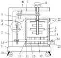
Referring to fig. 1-2, a printing and dyeing raw material mixing device comprises a base 1, wherein rollers 25 are symmetrically arranged on two sides of the lower end of the base 1 respectively, the rollers 25 are self-locking universal wheels, the moving capacity of the device is enhanced through the four rollers 25, the whole moving device is convenient, the rollers 25 can be self-locked when the device works, and the stability of the device during working is ensured.
The inner chamber top of mixing box 3 is rotated and is connected with (mixing) shaft 4, and the upper end of (mixing) shaft 4 runs through mixing box 3 and extends to the outside, the inner chamber lower part of mixing box 3 is rotated and is connected with axis of rotation 12, the outside of axis of rotation 12 evenly is equipped with puddler 13, the one end fixedly connected with scraper blade 14 of axis of rotation 12 is kept away from to puddler 13, when axis of rotation 12 rotates, can make scraper blade 14 scrape the inner wall bottom of mixing box 3, can avoid producing the sediment, improve the mixing effect, further improve the quality of ink-jet printing agent.
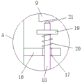
The left end of a rotating shaft 12 penetrates through a mixing box 3 and is fixedly sleeved with a gear 15, the left side of the outer wall of the mixing box 3 is provided with a through groove 10, a sealing bearing 11 matched with the through groove 10 is arranged inside the through groove 10, the sealing bearing 11 is sleeved outside the rotating shaft 12, the upper end of an L-shaped support 2 is provided with a speed reducing motor 8, the output shaft of the speed reducing motor 8 is connected with the upper end of a stirring shaft 4, the left side of the lower part of the horizontal section of the L-shaped support 2 is rotatably connected with a shaft body 5, the outer side of the middle part of the shaft body 5 and the outer side of the upper part of the stirring shaft 4 are both sleeved with belt pulleys 6, a belt 7 is in transmission connection between the two belt pulleys 6, the right side of the vertical section of the L-shaped support 2 is connected with a connecting rod 16, a chute 17 is arranged on the connecting rod 16, a rack rod 18 meshed with the gear, and reset spring 20 encircles in the outside of rack bar 18, and the lower extreme fixedly connected with of axis body 5 uses with rack bar 18 cooperation extrusion disc 9, and the upper end of rack bar 18 is seted up flutedly, and the inside of recess is equipped with ball 21, and the surface of ball 21 contacts with extrusion disc 9, can reduce the frictional force between rack bar 18 and the extrusion disc 9, improves the result of use of device.
The working principle is as follows: when the device is used, firstly, a plurality of printing and dyeing raw materials are added from the feeding pipe 22, then the speed reducing motor 8 is started, the stirring shaft 4 is driven by the speed reducing motor 8 to rotate, the raw materials in the mixing box 3 can be stirred, the stirring shaft 4 rotates and is matched with the upper belt pulley 6 and the belt 7, the shaft body 5 and the extrusion disc 9 can rotate, the extrusion disc 9 is in a shape which is convenient to move, the extrusion rack rod 18 moves, the elastic action of the reset spring 20 is matched, the rack rod 18 can be driven to reciprocate up and down, the gear 15 drives the stirring rod 13 to rotate forwards and backwards ceaselessly, the raw materials at the lower part of the mixing box 3 can roll ceaselessly, the fluidity of raw material liquid is enhanced, the plurality of raw materials can be in full contact, the uniform mixing effect can be improved, the raw materials can be prevented from precipitating at the bottom of the mixing box 3, and, then the on-off valve 24 on the discharging pipe 23 is manually opened, and the printing dye can flow out.
The above, only be the concrete implementation of the preferred embodiment of the present invention, but the protection scope of the present invention is not limited thereto, and any person skilled in the art is in the technical scope of the present invention, according to the technical solution of the present invention and the utility model, the concept of which is equivalent to replace or change, should be covered within the protection scope of the present invention.
Claims (5)
1. The printing and dyeing raw material mixing device comprises a base (1) and is characterized in that an L-shaped support (2) is connected to the left side of the upper end of the base (1), a mixing box (3) is arranged on the right side of the upper end of the base (1), the upper portion and the lower portion of the right side of the mixing box (3) are respectively communicated with a feeding pipe (22) and a discharging pipe (23), a switch valve (24) is arranged on the discharging pipe (23), a stirring shaft (4) is rotatably connected to the top of an inner cavity of the mixing box (3), the upper end of the stirring shaft (4) penetrates through the mixing box (3) and extends to the outside, the lower portion of the inner cavity of the mixing box (3) is rotatably connected with a rotating shaft (12), stirring rods (13) are uniformly arranged on the outside of the rotating shaft (12), a gear (15) is fixedly sleeved on the left end of the mixing box (3) in a penetrating manner, a through, the inside of logical groove (10) is equipped with sealed bearing (11) rather than the looks adaptation, just sealed bearing (11) cup joints in the outside of axis of rotation (12), gear motor (8) are installed to the upper end of L type support (2), the output shaft of gear motor (8) is connected with the upper end of (mixing) shaft (4), the lower part left side of L type support (2) horizontal segment rotates and is connected with axis body (5), the middle part outside of axis body (5) and the upper portion outside of (mixing) shaft (4) all cup joint belt pulley (6), and two the transmission is connected with belt (7) between belt pulley (6), the right side of L type support (2) vertical section is connected with connecting rod (16), spout (17) has been seted up on connecting rod (16), the inside sliding connection of spout (17) has rack bar (18) with gear (15) engaged with, the fixed stopper (19) that has cup jointed in the upper portion outside of rack pole (18), fixedly connected with reset spring (20) between the lower extreme of stopper (19) and the upper end of connecting rod (16), just reset spring (20) encircle in the outside of rack pole (18), the lower extreme fixedly connected with of axis body (5) uses with rack pole (18) cooperation extrusion disc (9).
2. The printing and dyeing raw material mixing device according to claim 1, characterized in that rollers (25) are symmetrically mounted on two sides of the lower end of the base (1), and the rollers (25) are self-locking universal wheels.
3. A printing and dyeing raw material mixing apparatus according to claim 1, characterized in that said feed pipe (22) is provided in plurality.
4. A printing and dyeing raw material mixing device according to claim 1, characterized in that a scraper (14) is fixedly connected to the end of the stirring rod (13) far from the rotating shaft (12).
5. A printing and dyeing raw material mixing device according to claim 1, characterized in that the rack bar (18) is provided with a groove at its upper end, and the groove is provided with balls (21) inside.
Priority Applications (1)
| Application Number | Priority Date | Filing Date | Title |
|---|---|---|---|
| CN201920335722.0U CN210097465U (en) | 2019-03-18 | 2019-03-18 | Printing and dyeing raw materials compounding device |
Applications Claiming Priority (1)
| Application Number | Priority Date | Filing Date | Title |
|---|---|---|---|
| CN201920335722.0U CN210097465U (en) | 2019-03-18 | 2019-03-18 | Printing and dyeing raw materials compounding device |
Publications (1)
| Publication Number | Publication Date |
|---|---|
| CN210097465U true CN210097465U (en) | 2020-02-21 |
Family
ID=69534488
Family Applications (1)
| Application Number | Title | Priority Date | Filing Date |
|---|---|---|---|
| CN201920335722.0U Active CN210097465U (en) | 2019-03-18 | 2019-03-18 | Printing and dyeing raw materials compounding device |
Country Status (1)
| Country | Link |
|---|---|
| CN (1) | CN210097465U (en) |
Cited By (1)
| Publication number | Priority date | Publication date | Assignee | Title |
|---|---|---|---|---|
| CN115487707A (en) * | 2022-09-29 | 2022-12-20 | 苏州市职业大学 | Disinfectant producing and processing equipment |
-
2019
- 2019-03-18 CN CN201920335722.0U patent/CN210097465U/en active Active
Cited By (1)
| Publication number | Priority date | Publication date | Assignee | Title |
|---|---|---|---|---|
| CN115487707A (en) * | 2022-09-29 | 2022-12-20 | 苏州市职业大学 | Disinfectant producing and processing equipment |
Similar Documents
| Publication | Publication Date | Title |
|---|---|---|
| CN210097465U (en) | Printing and dyeing raw materials compounding device | |
| CN114917814A (en) | Diversified intensive mixing equipment | |
| CN209317575U (en) | A kind of intense agitation device for magma slurry processing of weaving | |
| CN108704563A (en) | A kind of automation agitating device | |
| CN211514308U (en) | Gardens soil improvement is with high-efficient mixing stirring device | |
| CN114797674A (en) | Intermittent uniform feeding type chemical reaction kettle | |
| CN212467824U (en) | Environment-friendly asphalt emulsifying device | |
| CN108522573A (en) | A kind of efficient noodle device convenient for water filling | |
| CN208426883U (en) | A kind of uniformly mixed roller machine | |
| CN112680905A (en) | Automatic even sizing apparatus of cloth of batching | |
| CN112593369A (en) | Printing and dyeing raw material mixing drum | |
| CN213611075U (en) | Diluting device is used in processing of high-quality sodium silicate | |
| CN214982133U (en) | Brick agitated vessel permeates water | |
| CN216701509U (en) | Lactobacillus fermentation cylinder | |
| CN109822741B (en) | Mixer is used in processing of pottery drinking cup convenient to intensive mixing | |
| CN219631145U (en) | Blendor with improve stirring effect | |
| CN220546988U (en) | Cleaning device for rice production | |
| CN111300651A (en) | Concrete mixing device is used in water conservancy water and electricity construction | |
| CN210786936U (en) | Stirrer for preparing printing ink | |
| CN216321419U (en) | Dyestuff mixing arrangement is used in artificial leather processing | |
| CN210886597U (en) | Waste liquid treatment device for textile production | |
| CN213467654U (en) | Powder mixing device for powder metallurgy | |
| CN215241874U (en) | Novel cement stirring device for building construction | |
| CN214055972U (en) | Compounding device is used in rubber production | |
| CN215233879U (en) | Material mixing machine |
Legal Events
| Date | Code | Title | Description |
|---|---|---|---|
| GR01 | Patent grant | ||
| GR01 | Patent grant |