CN210077901U - Auxiliary positioning device for adhering accessories of invisible appliance - Google Patents
Auxiliary positioning device for adhering accessories of invisible appliance Download PDFInfo
- Publication number
- CN210077901U CN210077901U CN201920131894.6U CN201920131894U CN210077901U CN 210077901 U CN210077901 U CN 210077901U CN 201920131894 U CN201920131894 U CN 201920131894U CN 210077901 U CN210077901 U CN 210077901U
- Authority
- CN
- China
- Prior art keywords
- forceps
- invisible
- auxiliary
- accessories
- rod
- Prior art date
- Legal status (The legal status is an assumption and is not a legal conclusion. Google has not performed a legal analysis and makes no representation as to the accuracy of the status listed.)
- Active
Links
Images


Abstract
The utility model relates to an equipment technical field is rescued in the oral cavity, more specifically relates to an ware annex bonding supplementary ware of taking one's place is rescued in stealthy, including pliers, clamping part and fixed arc, fixed arc setting on the clamping part, two the clamping part set up the front end at the pliers relatively. The buccal surface of the transparent tooth socket can be tightly attached to the tooth surface, the tool does not influence light curing, and a plurality of accessories can be bonded at one time. The success rate and the efficiency of the attachment bonding are improved.
Description
Technical Field
The utility model relates to an equipment technical field is rescued in the oral cavity, more specifically relates to an ware is assisted in adhesion of ware annex takes one's place to stealthy rescue.
Background
Before invisible correction, resin accessories are needed to be bonded on the tooth surface, the purpose is to enable the transparent tooth socket to be tightly attached to the tooth surface to play a role in retention, and the accessories with irregular shapes can assist the teeth to move towards and away from the middle or towards the root control of the buccal tongue. The accessory is necessary in the invisible correcting process and can assist the correcting device to be in place and the resin bulge for tooth movement. The accuracy and success of attachment bonding is critical to invisible appliances. In clinical work, after the accessory transparent tooth socket is worn into the mouth, because the transparent tooth socket is too thin and has lower hardness, after the transparent tooth socket is closed to the in-place position, the buccal side of the tooth socket is easy to be separated from the tooth surface to be in close contact with the tooth surface, and the accessory template cannot be effectively attached to the tooth surface. In the light curing process of the resin, the resin cannot be tightly attached to the tooth surface, so that the attachment fails to be bonded, and further needs to be bonded repeatedly, or the attachment is bonded successfully but has small bonding force, so that the attachment falls off in the treatment process.
SUMMERY OF THE UTILITY MODEL
The utility model overcomes above-mentioned prior art an at least defect, provide an ware annex bonding supplementary taking one's place is rescued in stealthy, can make the buccal surface and the tooth surface of transparent facing hug closely, this instrument does not influence photocuring, can reach once bonding many annexs. The success rate and the efficiency of the attachment bonding are improved.
In order to solve the technical problem, the utility model discloses a technical scheme is: the utility model provides an ware annex bonding auxiliary position ware is rescued in stealthy, includes pliers, clamping part and fixed arc, fixed arc set up on the clamping part, two the clamping part set up the front end at the pliers relatively.
When carrying out stealthy the rescue in oral cavity, the patient is when wearing transparent facing, uses this device to carry out the fixed of position to transparent facing, opens the pliers, places the clamping part at the buccal of transparent facing and lingual face, adjusts the position of fixed arc, makes fixed arc centre gripping on the tooth that does not place the annex, closes the pliers, makes the fixed arc on the clamping part laminate with the lingual face and the buccal face of transparent facing to make transparent facing and flank of tooth laminating, play the effect of rigidity. The device can ensure that the transparent tooth socket is tightly attached to the teeth without influencing light curing, and can achieve the purpose of sequentially bonding a plurality of accessories so as to improve the success rate and the efficiency of accessory bonding.
Furthermore, the clamping part is provided with a sliding groove, a sliding rod is arranged in the sliding groove in a sliding mode, and the fixed arc is connected with the sliding rod.
Furthermore, the sliding rod is a telescopic rod.
Further, the telescopic link include the body of rod, spring and pole head, the body of rod in be equipped with and hold the chamber, the pole head slide to set up and holding the intracavity, the spring locate and hold the intracavity, the spring both ends be connected with the body of rod and pole head respectively. Because the pole head can be followed and held the chamber direction and stretch out and draw back, consequently the fixed arc that is connected with the pole head can carry out the automatic adaptation according to the concave-convex face of patient's flank of tooth to satisfy different patients' actual requirement, guarantee that every face that receives the centre gripping of fixed arc can both compress tightly the flank of tooth of transparent facing, guarantee to compress tightly transparent facing on the flank of tooth.
Furthermore, the fixed arc is an arc panel with the radian similar to that of the tooth surface. When the fixed arc compresses the transparent tooth socket, the fixed arc can compress each fixed tooth well, the pressing area is increased, and the transparent tooth socket can be better attached to the tooth surface.
Furthermore, the pliers comprise two pliers bodies hinged with each other, the front ends of the pliers bodies are pliers heads connected with the clamping part, and the tail ends of the pliers bodies are pliers handles. The doctor holds the forceps handles to operate the forceps, the forceps heads are opened when the two forceps handles are opened outwards, and the forceps heads are closed inwards when the two forceps handles are closed inwards to clamp the transparent tooth socket tightly.
Furthermore, the clamp handle is wrapped with an anti-skid layer. The friction between the tool and the hand of an operator can be increased through the anti-slip layer, and slipping during operation is avoided.
Furthermore, the anti-skid layer is silica gel with anti-skid lines on the surface.
Furthermore, the forceps, the clamping part and the fixed arc are all made of medical steel, and medical disinfection and repeated use can be performed after the forceps are used.
Compared with the prior art, the beneficial effects are: the device can make the buccal surface of the transparent tooth socket tightly attached to the tooth surface, the tool does not influence light curing, and a plurality of accessories can be bonded at one time. The success rate and the efficiency of the attachment bonding are improved.
Drawings
FIG. 1 is a schematic view of the overall structure of the present invention;
FIG. 2 is a schematic view of the present invention in use;
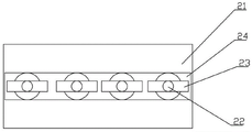
FIG. 3 is a schematic structural view of the clamping portion of the present invention;
fig. 4 is a schematic structural view of the sliding rod of the present invention.
Detailed Description
The drawings are for illustrative purposes only and are not to be construed as limiting the patent; for the purpose of better illustrating the embodiments, certain features of the drawings may be omitted, enlarged or reduced, and do not represent the size of an actual product; it will be understood by those skilled in the art that certain well-known structures in the drawings and descriptions thereof may be omitted. The positional relationships depicted in the drawings are for illustrative purposes only and are not to be construed as limiting the present patent.
As shown in figures 1-3, an auxiliary attachment bonding locator for an invisible appliance comprises a pair of pliers, a clamping portion 21 and a fixing arc 23, wherein the pliers comprise two pliers bodies hinged to each other, the front ends of the pliers bodies are provided with pliers heads 11 connected with the clamping portion 21, and the tail ends of the pliers bodies are provided with pliers handles 12. The two clamping parts 21 are oppositely arranged at the front ends of the pliers, sliding grooves 24 are formed in the clamping parts 21, sliding rods 22 are arranged in the sliding grooves 24 in a sliding mode, and the fixed arcs 23 are connected with the sliding rods 22.
As shown in fig. 2, fixed arc 23 is the cambered plate that is close with the flank radian, and the cambered plate adopts medical plastics to make, and it has elasticity, can adapt to the radian of tooth flank well, and when going on to the tooth clamp tightly, the cambered plate elasticity can open in order to laminate transparent facing, and when fixed arc 23 compressed tightly transparent facing, fixed arc 23 can compress tightly every fixed tooth well, and the area is pressed in the increase, guarantees that transparent facing can paste tight flank better.
In the embodiment, the forceps comprises two mutually hinged forceps bodies, the front end of each forceps body is a forceps head 11 connected with a clamping part 21, and the tail end of each forceps body is a forceps handle 12. The doctor holds the forceps handles 12 to operate the forceps, when the two forceps handles 12 are outwards opened, the forceps heads 11 are opened, when the two forceps handles 12 are inwards close to each other, the forceps heads 11 are inwards close to each other, and the transparent tooth socket is clamped tightly. In addition, in order to ensure that a doctor can exert force better when using the device, the length ratio of the forceps head 11 to the forceps handle 12 in the device is 1:3, so that a larger pressing force can be provided for the tooth socket when the device is used according to the lever principle, the transparent tooth socket can be ensured to be attached to the pressing surface, and the attaching firmness degree of the accessory can be ensured.
The forceps handle 12 is wrapped with an anti-slip layer 13. The friction between the tool and the hand of an operator can be increased through the anti-slip layer 13, and slipping during operation is avoided. Specifically, the anti-slip layer 13 is silica gel with anti-slip lines on the surface.
In this embodiment, the forceps, the holding portion 21 and the fixing arc 23 are all made of medical steel, and can be sterilized after use and reused.
When the invisible oral cavity is corrected, when a patient wears the transparent tooth socket, the position of the transparent tooth socket is fixed by using the device, a doctor operates the forceps handle 12 to open the forceps handle 12 to drive the forceps head 11 to open, the clamping part 21 is placed on the buccal surface and the lingual surface of the transparent tooth socket, the position of the fixed arc 23 is adjusted, the fixed arc 23 is clamped on teeth without accessories, the forceps are closed, and the fixed arc 23 on the clamping part 21 is attached to the lingual surface and the buccal surface of the transparent tooth socket, so that the transparent tooth socket is attached to the tooth surface, and the position fixing effect is achieved. The device can ensure that the transparent tooth socket is tightly attached to the teeth without influencing light curing, and can achieve the purpose of sequentially bonding a plurality of accessories so as to improve the success rate and the efficiency of accessory bonding.
Example 2:
the embodiment is similar to embodiment 1, except that in the embodiment, the fixing arc 23 is a hollow structure, and when light curing is performed, if the accessory covering area is inadvertently shielded, light can be irradiated through the hollow structure, so as to avoid being shielded. In addition, in particular, the fixed arc 23 can be made transparent, and the fixed arc 23 can be replaced, so that the fixed arc 23 can be replaced after each use, thereby ensuring sanitation.
Example 3:
the embodiment is similar to embodiment 1, except that in this embodiment, as shown in fig. 4, the sliding rod is a telescopic rod, the telescopic rod includes a rod body 221, a spring 222 and a rod head 223, an accommodating cavity is provided in the rod body 221, the rod head 223 is slidably disposed in the accommodating cavity, the spring 222 is disposed in the accommodating cavity, and two ends of the spring 222 are respectively connected to the rod body 221 and the rod head 223. Because the pole head 223 can be flexible along holding the chamber direction, consequently the fixed arc that is connected with pole head 223 can carry out the automatic adaptation according to the concave-convex face of patient's flank of tooth to satisfy different patients' actual requirement, guarantee that every receives the flank of tooth that the fixed arc centre gripping can both compress tightly transparent facing, guarantee to compress tightly transparent facing on the flank of tooth.
It is obvious that the above embodiments of the present invention are only examples for clearly illustrating the present invention, and are not limitations to the embodiments of the present invention. Other variations and modifications will be apparent to persons skilled in the art in light of the above description. And are neither required nor exhaustive of all embodiments. Any modification, equivalent replacement, and improvement made within the spirit and principle of the present invention should be included in the protection scope of the claims of the present invention.
Claims (9)
1. The utility model provides an auxiliary locator for adhering accessories of invisible orthodontic appliances, which is characterized by comprising pliers, clamping parts (21) and fixed arcs (23), wherein the fixed arcs (23) are arranged on the clamping parts (21), and the two clamping parts (21) are oppositely arranged at the front ends of the pliers.
2. The auxiliary adhering device for accessories of invisible orthodontic appliances as claimed in claim 1, wherein the holding portion (21) is provided with a sliding groove (24), the sliding groove (24) is internally provided with a sliding rod (22), and the fixed arc (23) is connected with the sliding rod (22).
3. The auxiliary attachment adhesion locator of the invisible appliance of claim 2, wherein the sliding rod is a telescopic rod.
4. The auxiliary adhering device for accessories of the invisible orthodontic appliance is characterized in that the telescopic rod comprises a rod body (221), a spring (222) and a rod head (223), a containing cavity is formed in the rod body (221), the rod head (223) is arranged in the containing cavity in a sliding mode, the spring (222) is arranged in the containing cavity, and two ends of the spring (222) are connected with the rod body (221) and the rod head (223) respectively.
5. The auxiliary attachment tacking device for an invisible appliance according to claim 1, wherein the fixing arc (23) is a cambered plate with a radian similar to that of the tooth surface.
6. The auxiliary attachment bonding locator for the invisible orthosis according to claim 1, wherein the forceps comprise two forceps bodies hinged to each other, the front ends of the forceps bodies are provided with forceps heads (11) connected with the clamping portions (21), and the tail ends of the forceps bodies are provided with forceps handles (12).
7. The auxiliary adhering device for the invisible appliance accessories is characterized in that the clamp handle (12) is wrapped with an anti-slip layer (13).
8. The auxiliary adhering locator for the invisible orthodontic appliance accessories is characterized in that the anti-skid layer (13) is silica gel with anti-skid lines on the surface.
9. The auxiliary attachment bonding locator of the invisible appliance is characterized in that the forceps, the holding part (21) and the fixing arc (23) are made of medical steel.
Priority Applications (1)
| Application Number | Priority Date | Filing Date | Title |
|---|---|---|---|
| CN201920131894.6U CN210077901U (en) | 2019-01-25 | 2019-01-25 | Auxiliary positioning device for adhering accessories of invisible appliance |
Applications Claiming Priority (1)
| Application Number | Priority Date | Filing Date | Title |
|---|---|---|---|
| CN201920131894.6U CN210077901U (en) | 2019-01-25 | 2019-01-25 | Auxiliary positioning device for adhering accessories of invisible appliance |
Publications (1)
| Publication Number | Publication Date |
|---|---|
| CN210077901U true CN210077901U (en) | 2020-02-18 |
Family
ID=69470794
Family Applications (1)
| Application Number | Title | Priority Date | Filing Date |
|---|---|---|---|
| CN201920131894.6U Active CN210077901U (en) | 2019-01-25 | 2019-01-25 | Auxiliary positioning device for adhering accessories of invisible appliance |
Country Status (1)
| Country | Link |
|---|---|
| CN (1) | CN210077901U (en) |
Cited By (1)
| Publication number | Priority date | Publication date | Assignee | Title |
|---|---|---|---|---|
| CN109717968A (en) * | 2019-01-25 | 2019-05-07 | 广州医科大学附属口腔医院(广州医科大学羊城医院) | A kind of invisible orthotic device accessory adhering auxiliary place device |
-
2019
- 2019-01-25 CN CN201920131894.6U patent/CN210077901U/en active Active
Cited By (1)
| Publication number | Priority date | Publication date | Assignee | Title |
|---|---|---|---|---|
| CN109717968A (en) * | 2019-01-25 | 2019-05-07 | 广州医科大学附属口腔医院(广州医科大学羊城医院) | A kind of invisible orthotic device accessory adhering auxiliary place device |
Similar Documents
| Publication | Publication Date | Title |
|---|---|---|
| US6280184B1 (en) | Method and apparatus for removing bonded dental appliances | |
| US10307223B1 (en) | Tooth aligner removal device | |
| US5538421A (en) | Dental instrument | |
| CN207186603U (en) | Novel mouth oral maxillofacial surgery dilator | |
| US5122058A (en) | Forceps with inserts for removing premolar and anterior dental crowns | |
| CN210077901U (en) | Auxiliary positioning device for adhering accessories of invisible appliance | |
| US20110045435A1 (en) | Dental pliers | |
| US6386873B1 (en) | Dental tool | |
| CN210095949U (en) | Multipurpose tool for assisting in adhering accessories of invisible orthodontic appliance | |
| CN204521001U (en) | Bracket pincers are spent for two of metal/ceramic bracket | |
| CN211433401U (en) | Arc button shearing pliers | |
| CN109717968A (en) | A kind of invisible orthotic device accessory adhering auxiliary place device | |
| CN201131734Y (en) | A pincer-like mouth-gag with denture cushion | |
| CN211834788U (en) | Tooth surface bracket pliers | |
| CN207520223U (en) | Gear division auxiliary bonding stick | |
| CN216318081U (en) | Dental forceps for oral and maxillofacial surgery | |
| CN219271174U (en) | Dental forceps for assisting in bonding of invisible appliance accessories | |
| CN216257493U (en) | Grid pliers for adhering tongue side buckle of invisible appliance | |
| CN217066630U (en) | Auxiliary fixing rod for adhering accessories of invisible appliance | |
| CN215228622U (en) | Invisible appliance anterior tooth flat guide forming pliers | |
| CN217525405U (en) | Be applied to tongue side of stealthy ware chair side cutting of rescuring and detaining pincers of windowing | |
| CN215019328U (en) | Pincers for oral medical rehabilitation | |
| CN218922829U (en) | Tweezers | |
| US20040091836A1 (en) | Dental appliance and method for holding and repositioning a veneer during bonding and cementation process | |
| CN214857670U (en) | Occlusion in-place device for oral invisible orthodontic attachment adhesive template |
Legal Events
| Date | Code | Title | Description |
|---|---|---|---|
| GR01 | Patent grant | ||
| GR01 | Patent grant |