CN210061628U - Lifting platform for cutting machine and ceramic tile cutting machine - Google Patents
Lifting platform for cutting machine and ceramic tile cutting machine Download PDFInfo
- Publication number
- CN210061628U CN210061628U CN201920418894.4U CN201920418894U CN210061628U CN 210061628 U CN210061628 U CN 210061628U CN 201920418894 U CN201920418894 U CN 201920418894U CN 210061628 U CN210061628 U CN 210061628U
- Authority
- CN
- China
- Prior art keywords
- lifting
- fixed
- cutting machine
- lifting platform
- cutting
- Prior art date
- Legal status (The legal status is an assumption and is not a legal conclusion. Google has not performed a legal analysis and makes no representation as to the accuracy of the status listed.)
- Expired - Fee Related
Links
- 239000000919 ceramic Substances 0.000 title claims abstract description 17
- 230000005540 biological transmission Effects 0.000 claims description 49
- 239000003638 chemical reducing agent Substances 0.000 claims description 21
- 230000033001 locomotion Effects 0.000 claims description 6
- 230000001360 synchronised effect Effects 0.000 claims description 4
- 238000000034 method Methods 0.000 abstract description 15
- 230000004308 accommodation Effects 0.000 abstract description 5
- 230000002349 favourable effect Effects 0.000 abstract description 5
- 238000003754 machining Methods 0.000 abstract description 4
- 239000004575 stone Substances 0.000 description 12
- 230000009286 beneficial effect Effects 0.000 description 6
- 239000000463 material Substances 0.000 description 6
- 238000010586 diagram Methods 0.000 description 2
- 238000009434 installation Methods 0.000 description 2
- 241001391944 Commicarpus scandens Species 0.000 description 1
- 238000005034 decoration Methods 0.000 description 1
- 230000007547 defect Effects 0.000 description 1
- 238000005516 engineering process Methods 0.000 description 1
- 230000000630 rising effect Effects 0.000 description 1
- 238000006467 substitution reaction Methods 0.000 description 1
Images


Abstract
The utility model relates to a lifting platform for a cutting machine and a tile cutting machine, which comprises a movable part and a fixed part, wherein the movable part is used for installing a motor and a cutting blade, the fixed part is used for installing a guide rail, the movable part is connected with the fixed part and forms a moving pair which can move up and down along the vertical direction together with the fixed part; the utility model discloses, compact structure in the course of working of ceramic tile, can make things convenient for, swift, the high of efficient regulation cutting piece, not only can accurate control fluting and depth of cut, finely tune etc. after cutting piece wearing and tearing, be favorable to simplifying the operation in the accommodation process moreover, improve machining precision and efficiency.
Description
Technical Field
The utility model relates to a cutting means technical field, concretely relates to a lift platform and ceramic tile cutting machine for cutting machine.
Background
The cutting machine is a common tool for cutting boards such as ceramic tiles and the like; cutting machine among the prior art includes the workstation usually, rail brackets, sliding platform, motor and cutting piece etc, the workstation is used for placing or settling the ceramic tile that is cut, rail brackets includes guide rail and two backup pads usually, the both ends of guide rail are fixed in the backup pad respectively, the backup pad is fixed in the workstation respectively, sliding platform sets up on the guide rail, sliding platform is fixed in respectively to motor and cutting piece, and the output shaft of motor passes through drive mechanism and links to each other with the cutting piece, so that the drive cutting piece rotates, sliding platform can follow the guide rail and slide, so that the cutting piece can cut along the length direction of guide rail.
However, the cutting machines commonly used in the prior art, especially the portable small-sized cutting machines, generally have some disadvantages in the actual use process, for example, because of the difference of the model and material of the tile and the requirement of the personalized decoration, various shapes and shapes are generally required to be performed on the surface of the tile or the stone, such as processing grooves (i.e. slots) with various depths, and the like, while the existing cutting machines either cannot adjust the height of the cutting blade along the vertical direction (i.e. cannot adjust the distance between the cutting blade and the workbench), and only can be used for cutting through the tile or the stone, but cannot shape the surface of the tile or the stone, not only the use occasion is limited, but also when the tile or the stone with larger thickness is cut, the cutting blade is easy to break; or can only realize the regulation to the cutting blade height through the mounting height of adjusting the guide rail, not only troublesome poeration, consuming time long, inefficiency, moreover in actual accommodation process, destroy the levelness of guide rail easily to make the groove depth of cutting out on ceramic tile or stone material surface differ, influence pleasing to the eye.
SUMMERY OF THE UTILITY MODEL
An object of the utility model is to improve the not enough that exists among the prior art, provide a lift platform for cutting machine, compact structure can make things convenient for, swiftly, the height of cutting piece is adjusted to the efficient, is favorable to the simplified operation, improves machining precision and efficiency.
The utility model adopts the technical proposal that:
a lift platform for cutting machine, including movable part and fixed part, the movable part is used for installing motor and cutting piece, the fixed part is used for installing in the guide rail, the movable part with the fixed part links to each other to constitute the sliding pair that can follow vertical direction up/down movement with the fixed part.
Furthermore, the device also comprises a hand wheel and a first transmission mechanism, wherein one end of the first transmission mechanism is connected with the hand wheel, the other end of the first transmission mechanism is connected with the movable part, and the hand wheel is used for controlling the movable part to move up and down through the first transmission mechanism.
In the preferred scheme, the fixed part includes mounting panel and lift sliding sleeve, be provided with the through-hole on the mounting panel, the lift sliding sleeve is fixed in the through-hole, the lift sliding sleeve be used for with the lift slide bar constitute the sliding pair.
Furthermore, the installation plate is fixed on the sliding blocks, and the sliding blocks are arranged on the guide rails and are used for forming sliding pairs with the guide rails.
Optionally, the lifting sliding sleeve is provided with a central through hole, the outer side of the lifting sliding sleeve is provided with a step and an external thread, and the external thread is used for connecting a locking nut.
Optionally, the lifting sliding sleeve is provided with a central through hole, one end of the lifting sliding sleeve is provided with an annular flange, and the annular flange is provided with a plurality of mounting holes.
In the preferred scheme, the movable part includes first backup pad, second backup pad and a plurality of lift slide bar, wherein, lift slide bar's both ends respectively with first backup pad and second backup pad link to each other, and the vertical setting of lift slide bar for constitute the sliding pair with lift sliding sleeve, first backup pad is used for installing the motor, and the second backup pad is used for fixed transmission shaft continuous with the cutting piece.
Preferably, the lifting slide bar is a hollow round bar, and the two ends of the lifting slide bar are respectively provided with internal threads for connecting fastening bolts.
In the preferred scheme, the lifting slide sleeve comprises four lifting slide sleeves and four lifting slide rods, wherein the four lifting slide sleeves form a rectangular structure, and each lifting slide rod is matched with each lifting slide sleeve.
In the preferred scheme, first drive mechanism includes gear shaft, gear and rack, the length direction of rack with lift slide bar length direction is parallel, and the both ends of rack are fixed in respectively first backup pad and second backup pad, and the rack meshes with the gear mutually, and the gear is fixed in the gear shaft, the gear shaft is fixed in through the support the fixed part, the one end of gear shaft with the hand wheel links to each other.
Furthermore, the hand wheel type gear reducer further comprises a speed reducer, wherein the speed reducer is fixed on the fixing portion, the hand wheel is connected with an input shaft of the speed reducer, and an output shaft of the speed reducer is connected with the gear shaft.
Preferably, the support may be a bearing seat.
Preferably, the mounting plate is provided with a hole for passing through the rack.
In a preferred scheme, the device comprises two racks, two gears are arranged on the gear shaft, and the two gears are respectively meshed with the two racks to realize synchronous motion.
The utility model provides a ceramic tile cutting machine, includes guide rail, motor, transmission shaft, cutting piece, second drive mechanism and aforementioned lift platform, wherein, the fixed part is fixed in the guide rail, the motor is fixed in the movable part, the output shaft of motor passes through second drive mechanism with the transmission shaft links to each other, the transmission shaft is fixed in the movable part, transmission shaft are used for installing the cutting piece.
Preferably, the second transmission mechanism is a belt transmission mechanism or a gear transmission mechanism or a chain transmission mechanism.
Compared with the prior art, use the utility model provides a pair of a lift platform and ceramic tile cutting machine for cutting machine has following beneficial effect:
1. this lift platform, compact structure in the course of working of ceramic tile or stone material, can make things convenient for, swiftly, the high of efficient regulation cutting piece, not only can accurate control fluting and depth of cut, finely tune etc. after cutting piece wearing and tearing, be favorable to simplifying the operation in the course of adjusting moreover, improve machining precision and efficiency.
2. The lifting platform is stable in lifting/lowering process, and the relative position relation between the guide rail and the lower workbench is not changed in the adjusting process, namely the adjusting process is irrelevant to the guide rail, so that the defects in the prior art can be effectively overcome.
3. This lift platform, at the in-process of rising/falling, motor, cutting piece and with motor and cutting piece between drive disk assembly class synchronous motion for accommodation process does not influence the transmission between motor and the cutting piece, is favorable to adjusting at any time at the in-process of motor and cutting piece work, unusual convenience.
4. This ceramic tile cutting machine, the cutting piece is installed in the lift platform that has the lift function for this ceramic tile cutting machine more accords with the demand of ceramic tile, stone material processing technology, and application scope is wider.
Drawings
In order to more clearly illustrate the technical solutions of the embodiments of the present invention, the drawings that are required to be used in the embodiments will be briefly described below, it should be understood that the following drawings only illustrate some embodiments of the present invention, and therefore should not be considered as limiting the scope, and for those skilled in the art, other related drawings can be obtained according to the drawings without inventive efforts.
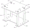
Fig. 1 is a schematic structural diagram of a mounting plate in a lifting platform provided in embodiment 1 of the present invention.
Fig. 2 is a schematic structural view of the mounting plate fixed to the guide rail through the slider in the lifting platform provided in embodiment 1 of the present invention.
Fig. 3 is a schematic structural view of a lifting sliding sleeve in a lifting platform provided in embodiment 1 of the present invention.
Fig. 4 is a schematic structural view of another lifting sliding sleeve in the lifting platform provided in embodiment 1 of the present invention.
Fig. 5 is a schematic structural view of a movable portion in the lifting platform provided in embodiment 1 of the present invention.
Fig. 6 is a front partial sectional view of a lifting platform provided in embodiment 1 of the present invention.
Fig. 7 is a schematic rear view of a lifting platform provided in embodiment 1 of the present invention.
Fig. 8 is a schematic structural diagram of a support in the lifting platform provided in embodiment 1 of the present invention.
Fig. 9 is a partial schematic view (side view) of a tile cutting machine provided in embodiment 1 of the present invention.
Description of the drawings
The device comprises a fixing part 101, a mounting plate 102, a lifting sliding sleeve 103, a through hole 104, a sliding block 105, a central through hole 106, a step 107, an external thread 108, an annular flange 109, a mounting hole 110, a hole 111 and a locking nut 112;
the device comprises a movable part 201, a first support plate 202, a second support plate 203, a lifting slide bar 204 and a fastening bolt 205;
a hand wheel 301, a speed reducer 302, a gear shaft 303, a gear 304, a rack 305, a support 306, a connecting hole 307, a notch 308 and a fixing hole 309;
Detailed Description
The technical solutions in the embodiments of the present invention will be described clearly and completely with reference to the accompanying drawings in the embodiments of the present invention, and it is obvious that the described embodiments are only some embodiments of the present invention, not all embodiments. The components of embodiments of the present invention, as generally described and illustrated in the figures herein, may be arranged and designed in a wide variety of different configurations. Thus, the following detailed description of the embodiments of the present invention, presented in the accompanying drawings, is not intended to limit the scope of the invention, as claimed, but is merely representative of selected embodiments of the invention. Based on the embodiment of the present invention, all other embodiments obtained by the person skilled in the art without creative work belong to the protection scope of the present invention.
Example 1
Referring to fig. 2, 5, 6 and 7, in this embodiment, there is provided a lifting platform for a cutting machine, including a movable portion 201 and a fixed portion 101, wherein the movable portion 201 is used for mounting a motor 401 and a cutting blade 403, the fixed portion 101 is used for mounting on a guide rail 404 and can move along a length direction of the guide rail 404, the movable portion 201 is connected to the fixed portion 101 and forms a moving pair capable of moving up/down along a vertical direction with the fixed portion 101, that is, the movable portion 201 can move up/down relative to the fixed portion 101 and synchronously drive the motor 401 and the cutting blade 403 disposed thereon to move up/down, so as to effectively adjust a distance between the cutting blade 403 and a tile or stone below, thereby conveniently performing various shapes on surfaces of the tile and stone, especially processing grooves with different depths, compared with a common cutting machine (especially a portable small-sized cutting machine) in the prior art, not only small in size, compact structure can be convenient, swift, the high of efficient regulation cutting piece 403, both can accurate control fluting and depth of cut, finely tune etc. after cutting piece 403 is worn and torn, be favorable to simplifying the operation in the accommodation process again, improve machining precision and efficiency, in addition at the in-process of adjusting, can not change the relative position relation between guide rail 404 and the below workstation, accommodation process is irrelevant with guide rail 404 promptly to can effectively solve the drawback among the prior art.
In order to adjust the height conveniently, in a further scheme, the height adjusting device further comprises a hand wheel 301 and a first transmission mechanism, one end of the first transmission mechanism is connected with the hand wheel 301, the other end of the first transmission mechanism is connected with the movable part 201, and the hand wheel 301 is used for controlling the movable part 201 to move up and down through the first transmission mechanism; that is, when the height of the cutting blade 403 (i.e. the distance between the cutting blade 403 and the worktable) needs to be adjusted, only the hand wheel 301 needs to be rotated, and the hand wheel 301 drives the movable portion 201 to move up/down in the vertical direction relative to the fixed portion 101 through the first transmission mechanism, so that the adjustment can be completed more conveniently and more laborsavingly.
In a preferred scheme, the fixing portion 101 includes a mounting plate 102 and a lifting sliding sleeve 103, a through hole 104 is formed in the mounting plate 102, the lifting sliding sleeve 103 is fixed to the through hole 104, and the lifting sliding sleeve 103 and a lifting sliding rod 204 form a moving pair; for example, as shown in fig. 1, the mounting plate 102 is a flat plate and has a convex structure.
In a further scheme, the device further comprises a plurality of sliding blocks 105, the mounting plate 102 is fixed to the sliding blocks 105, the sliding blocks 105 are arranged on the guide rails 404 and are used for forming a moving pair with the guide rails 404, namely, the sliding blocks 105 can slide along the guide rails 404; for example, as shown in fig. 2, the slider 105 needs to be adapted to the guide rail 404 of the cutting machine, so that the slider 105 cannot fall off the guide rail 404 after being disposed on the guide rail 404, and can slide along the length direction of the guide rail 404 for cutting, it can be understood that the slider 105 can be fixed to the mounting plate 102 by bolts, thereby indirectly fixing the mounting plate 102, so that the mounting plate 102 can only move along the length direction of the guide rail 404 under the driving of the slider 105.
In a preferred scheme, the lifting sliding sleeve 103 is provided with a central through hole 106, the central through hole 106 is used for being matched with the lifting sliding rod 204, in a preferred scheme, the outer side of the lifting sliding sleeve 103 is provided with a step 107 and an external thread 108, and the external thread 108 is used for connecting a locking nut 112 so as to fix the lifting sliding sleeve 103 to the mounting plate 102; as shown in fig. 3, the lifting sliding sleeve 103 is a stepped cylinder, the external thread 108 is disposed on the cylinder with a smaller diameter, when installing, one end of the lifting sliding sleeve 103 passes through the through hole 104 on the mounting plate 102 and is fixed by the locking nut 112, for example, in this example, the locking nut 112 is a round nut.
In another possible solution, one end of the lifting sliding sleeve 103 is provided with an annular flange 109, and the annular flange 109 is provided with a plurality of mounting holes 110, as shown in fig. 4, and the lifting sliding sleeve 103 can be fixed to the mounting plate 102 by using the mounting holes 110.
As shown in fig. 5 or fig. 6, in a preferred embodiment provided in this embodiment, the movable portion 201 includes a first support plate 202, a second support plate 203, and a plurality of lifting slide bars 204, wherein two ends of the lifting slide bars 204 are respectively connected to the first support plate 202 and the second support plate 203, the lifting slide bars 204 are vertically disposed to form a moving pair with the lifting slide sleeve 103, the first support plate 202 is used to mount a motor 401, and the second support plate 203 is used to fix a transmission shaft 402 connected to the cutting blade 403, so that the motor 401 and the cutting blade 403 have a fixed positional relationship; when the height of the cutting blade 403 is adjusted, the movable part 201 moves integrally, so that the motor 401 and the cutting blade 403 are driven to move synchronously, transmission between the motor 401 and the cutting blade 403 is not affected, and adjustment can be performed at any time in the working process (rotating process) of the motor 401 and the cutting blade 403.
In a preferred scheme, the lifting slide bar 204 is a hollow round bar, and two ends of the lifting slide bar 204 are respectively provided with an internal thread for connecting a fastening bolt 205; for example, the first support plate 202 and the second support plate 203 are respectively provided with a through hole 104, and the fastening bolt 205 is connected to the lifting slide bar 204 through the through hole 104, as shown in fig. 6.
By way of example, in the preferred embodiment provided by the present invention, four lifting sliding sleeves 103 and four lifting sliding rods 204 are included, the four lifting sliding sleeves 103 form a rectangular structure, as shown in fig. 5 or fig. 6, each lifting sliding rod 204 is respectively matched with each lifting sliding sleeve 103; in the scheme, the four lifting slide bars 204 are adopted to support the first support plate 202 and the second support plate 203, so that on one hand, the rigidity of the whole lifting platform is higher, and the motor 401 is stably and firmly supported; on the other hand, four lifting slide bars 204 and four lifting slide sleeves 103 can respectively form four sliding pairs, which is beneficial to more uniform stress and more stable movement when the movable part 201 moves relative to the fixed part 101, thereby being beneficial to more stable adjustment of the position of the cutting blade 403.
In a preferred embodiment, the first transmission mechanism includes a gear shaft 303, a gear 304 and a rack 305, a length direction of the rack 305 is parallel to a length direction of the lifting slide bar 204 so as to be movable along the length direction of the lifting slide bar 204 under the driving action of the rack 305, two ends of the rack 305 are respectively fixed to the first support plate 202 and the second support plate 203, that is, the rack 305 is vertically arranged between the first support plate 202 and the second support plate 203, the rack 305 is meshed with the gear 304 so as to perform transmission, the gear 304 is fixed to the gear shaft 303, the gear shaft 303 is fixed to the fixing portion 101 through a support 306, and one end of the gear shaft 303 is connected to the handwheel 301. As shown in fig. 6 and 7, in this embodiment, the gear shaft 303 is fixed to the mounting plate 102 of the fixing portion 101 through the support 306, when the height of the cutting blade 403 needs to be adjusted, a user may rotate the hand wheel 301 to drive the gear shaft 303 to rotate, so that the drive gear 304 rotates, and then the drive rack 305 moves upward or downward, so that the movable portion 201 moves upward or downward as a whole, and the adjustment of the position of the cutting blade 403 is achieved.
In a further scheme, the lifting platform further comprises a speed reducer 302, as shown in fig. 6 or fig. 7, the speed reducer 302 is fixed to the fixing portion 101, the hand wheel 301 is connected to an input shaft of the speed reducer 302, and an output shaft of the speed reducer 302 is connected to the gear shaft 303; the speed reducer 302 is used for reducing the rotating speed, so that the adjustment precision is improved, and meanwhile, the speed reducer 302 can improve the torque and is beneficial to carrying the motor 401 with larger weight; in this embodiment, the speed reducer 302 may adopt the speed reducer 302 with a self-locking function in the prior art, that is, when the external force is removed, the speed reducer 302 may be locked at the current position, so as to prevent the gear shaft 303 from automatically rotating, which is beneficial to stably fixing the cutting blade 403 at a required position; the reducer 302 with the self-locking function is a reducer 302 commonly used in the prior art, and has various models in the market, and the description is omitted.
In a preferred scheme, the support 306 for supporting the gear shaft 303 can be a bearing seat; the support 306 shown in fig. 8 can also be used, the support 306 is provided with a connecting hole 307, a notch 308 and a through hole 104, as shown in fig. 8, the notch 308 is communicated with the connecting hole 307, the diameter of the connecting hole 307 can be larger than the outer diameter of the gear shaft 303, the gear shaft 303 passes through the connecting hole 307 and can rotate relative to the connecting hole 307, a bolt can be arranged at the through hole 104, and the size of the gap between the connecting hole 307 and the gear shaft 303 can be effectively adjusted by adjusting the tightness of the bolt; as shown in fig. 8, the support 306 is further provided with a fixing hole 309 for connecting the mounting plate 102, so as to facilitate installation.
As shown in fig. 1, a hole 111 is provided in the mounting plate 102, and the hole 111 is adapted to pass through the rack 305 so that the movable portion 201 can move up/down with respect to the mounting plate 102.
As shown in fig. 6 or fig. 7, in a preferred embodiment provided in this embodiment, the lifting platform includes two racks 305, two gears 304 are disposed on the gear shaft 303, and the two gears 304 are respectively engaged with the two racks 305 to realize synchronous movement; that is, when the gear shaft 303 is driven to rotate manually, the two gears 304 engaged with the gear shaft 303 can rotate synchronously, so that the two racks 305 are driven to move synchronously, which is beneficial to more stable transmission.
Example 2
The embodiment provides a tile cutting machine, which comprises a guide rail 404, a motor 401, a transmission shaft 402, a second transmission mechanism 405 and the lifting platform, as shown in fig. 9, the fixing portion 101 is fixed to the guide rail 404 and can slide along the length direction of the guide rail 404, the motor 401 is fixed to the movable portion 201, an output shaft of the motor 401 is connected with the transmission shaft 402 through the second transmission mechanism 405, the transmission shaft 402 is fixed to the movable portion 201, the transmission shaft 402 is used for installing a cutting blade 403, the second transmission mechanism 405 can be a belt transmission mechanism or a gear 304 transmission mechanism or a chain transmission mechanism, etc., and the motor 401 drives the cutting blade 403 to rotate through the second transmission mechanism 405, thereby achieving the cutting function.
For example, as shown in fig. 6, 7, or 9, the tile cutting machine provided in this embodiment includes two guide rails 404, the two guide rails 404 are respectively horizontally fixed above the working table, four sliding blocks 105 matched with the guide rails 404 are disposed on the mounting plate 102 of the fixing portion 101, and the lifting platform provided in embodiment 1 is fixed to the guide rails 404 through the matching of the sliding blocks 105 and the guide rails 404, so that when the tile cutting machine is used, the cutting blade 403 can not only cut along the length direction of the guide rails 404, but also the height of the cutting blade 403 from the lower working table can be adjusted, which is more convenient for performing various shapes on the surface of the tile stone, such as processing grooves with different depths, etc.; in this example, the second transmission 405 is a belt transmission.
In further scheme, this ceramic tile cutting machine still includes workstation, guide rail 404 support, and wherein, the both ends of guide rail 404 are fixed in guide rail 404 support respectively, and the guide rail 404 support is fixed in the workstation for guide rail 404 is located the top of workstation, and the workstation is used for placing ceramic tile, stone material etc. and is used for fixing ceramic tile or stone material, so that process, and it is no longer repeated here.
The above description is only for the specific embodiments of the present invention, but the protection scope of the present invention is not limited thereto, and any person skilled in the art can easily think of the changes or substitutions within the technical scope of the present invention, and all should be covered within the protection scope of the present invention.
Claims (10)
1. The utility model provides a lift platform for cutting machine, its characterized in that includes movable part and fixed part, the movable part is used for installing motor and cutting piece, the fixed part is used for installing in the guide rail, the movable part with the fixed part links to each other to constitute the sliding pair that can follow vertical direction up/down and move with the fixed part.
2. The lifting platform for the cutting machine as claimed in claim 1, further comprising a hand wheel and a first transmission mechanism, wherein one end of the first transmission mechanism is connected with the hand wheel, the other end of the first transmission mechanism is connected with the movable portion, and the hand wheel is used for controlling the movable portion to move up and down through the first transmission mechanism.
3. The lifting platform for the cutting machine as claimed in claim 2, wherein the fixing portion comprises a mounting plate and a lifting sliding sleeve, the mounting plate is fixed to the sliding block, a through hole is formed in the mounting plate, the lifting sliding sleeve is fixed to the through hole, and the lifting sliding sleeve and the lifting sliding rod form a sliding pair.
4. The lifting platform for the cutting machine as claimed in claim 3, wherein the lifting sliding sleeve is provided with a central through hole, the outer side of the lifting sliding sleeve is provided with a step and an external thread, the external thread is used for connecting a locking nut, or one end of the lifting sliding sleeve is provided with an annular flange, and the annular flange is provided with a plurality of mounting holes.
5. The lifting platform for the cutting machine according to claim 3, wherein the movable portion comprises a first support plate, a second support plate and a plurality of lifting slide bars, wherein two ends of each lifting slide bar are respectively connected with the first support plate and the second support plate, the lifting slide bars are vertically arranged and used for forming a sliding pair with the lifting sliding sleeve, the first support plate is used for installing a motor, and the second support plate is used for fixing a transmission shaft connected with the cutting blade.
6. The lifting platform for cutting machines as claimed in claim 5, characterized by comprising four lifting sliding sleeves and four lifting sliding rods, wherein the four lifting sliding sleeves form a rectangular structure, and each lifting sliding rod is respectively matched with each lifting sliding sleeve.
7. The lifting platform for a cutting machine according to any one of claims 5 to 6, wherein the first transmission mechanism comprises a gear shaft, a gear and a rack, the length direction of the rack is parallel to the length direction of the lifting slide bar, two ends of the rack are respectively fixed to the first support plate and the second support plate, the rack is meshed with the gear, the gear is fixed to the gear shaft, the gear shaft is fixed to the fixing portion through a support, and one end of the gear shaft is connected to the hand wheel.
8. The lifting platform for a cutting machine as claimed in claim 7, further comprising a reducer, wherein the reducer is fixed to the fixing portion, the hand wheel is connected to an input shaft of the reducer, and an output shaft of the reducer is connected to the gear shaft.
9. The lifting platform for the cutting machine as claimed in claim 7, wherein the lifting platform comprises two racks, two gears are arranged on the gear shaft, and the two gears are respectively meshed with the two racks to realize synchronous movement.
10. A ceramic tile cutting machine is characterized by comprising a guide rail, a motor, a transmission shaft, a second transmission mechanism and the lifting platform according to any one of claims 1 to 9, wherein the fixed part is fixed on the guide rail, the motor is fixed on the movable part, an output shaft of the motor is connected with the transmission shaft through the second transmission mechanism, the transmission shaft is fixed on the movable part, and the transmission shaft is used for installing a cutting blade.
Priority Applications (1)
| Application Number | Priority Date | Filing Date | Title |
|---|---|---|---|
| CN201920418894.4U CN210061628U (en) | 2019-03-29 | 2019-03-29 | Lifting platform for cutting machine and ceramic tile cutting machine |
Applications Claiming Priority (1)
| Application Number | Priority Date | Filing Date | Title |
|---|---|---|---|
| CN201920418894.4U CN210061628U (en) | 2019-03-29 | 2019-03-29 | Lifting platform for cutting machine and ceramic tile cutting machine |
Publications (1)
| Publication Number | Publication Date |
|---|---|
| CN210061628U true CN210061628U (en) | 2020-02-14 |
Family
ID=69435215
Family Applications (1)
| Application Number | Title | Priority Date | Filing Date |
|---|---|---|---|
| CN201920418894.4U Expired - Fee Related CN210061628U (en) | 2019-03-29 | 2019-03-29 | Lifting platform for cutting machine and ceramic tile cutting machine |
Country Status (1)
| Country | Link |
|---|---|
| CN (1) | CN210061628U (en) |
Cited By (1)
| Publication number | Priority date | Publication date | Assignee | Title |
|---|---|---|---|---|
| CN109877983A (en) * | 2019-03-29 | 2019-06-14 | 四川省万光机械设备有限公司 | A kind of hoistable platform and ceramic tile cutter for ceramic tile cutter |
-
2019
- 2019-03-29 CN CN201920418894.4U patent/CN210061628U/en not_active Expired - Fee Related
Cited By (1)
| Publication number | Priority date | Publication date | Assignee | Title |
|---|---|---|---|---|
| CN109877983A (en) * | 2019-03-29 | 2019-06-14 | 四川省万光机械设备有限公司 | A kind of hoistable platform and ceramic tile cutter for ceramic tile cutter |
Similar Documents
| Publication | Publication Date | Title |
|---|---|---|
| CN108381216A (en) | A kind of mechanical arm production clamping device | |
| CN207683203U (en) | A kind of U shaft clamping devices on digital-controlled carving machine | |
| CN109202177B (en) | Full-automatic alloy saw blade top grinding and surface grinding machine | |
| CN215202817U (en) | Novel multitool marble cutter | |
| CN210061628U (en) | Lifting platform for cutting machine and ceramic tile cutting machine | |
| CN101444932B (en) | Bridge-type double beam-guided multi-blade stone cutter | |
| CN208662718U (en) | A kind of sheet fabrication center | |
| CN100372662C (en) | Saw blade lifting regulation driving mechanism of table saw | |
| CN202782418U (en) | Carpentry engraving machine | |
| CN203236936U (en) | Carving machine for cutting die | |
| CN210549503U (en) | Adjustable machine tool base | |
| CN209869086U (en) | Cutting table and cutting machine | |
| CN102343757A (en) | Multifunctional three-dimensional engraving machine | |
| CN111975117B (en) | Free-form surface ultrasonic vibration cutting device | |
| CN204035639U (en) | A kind of U-shaped fork connector production miller | |
| CN210817572U (en) | Guider is used in mould production | |
| CN209920881U (en) | Vertical engraving machine | |
| CN109877983A (en) | A kind of hoistable platform and ceramic tile cutter for ceramic tile cutter | |
| CN210060721U (en) | Multifunctional vertical stone edge grinding machine | |
| CN210025854U (en) | Quick centering mechanism for ceramic tile cutting machine | |
| CN209869085U (en) | A main shaft and cutting machine for ceramic tile cutting machine | |
| CN202162464U (en) | High-precision automatic gear chamfering machine | |
| CN216966361U (en) | Punching equipment for steel structure machining production | |
| CN219786801U (en) | Four-way synchronous chamfering machine | |
| CN217619521U (en) | Wire drawing device for metal surface machining |
Legal Events
| Date | Code | Title | Description |
|---|---|---|---|
| GR01 | Patent grant | ||
| GR01 | Patent grant | ||
| CF01 | Termination of patent right due to non-payment of annual fee |
Granted publication date: 20200214 |