CN210059262U - Glass product cleaning device - Google Patents
Glass product cleaning device Download PDFInfo
- Publication number
- CN210059262U CN210059262U CN201920772905.9U CN201920772905U CN210059262U CN 210059262 U CN210059262 U CN 210059262U CN 201920772905 U CN201920772905 U CN 201920772905U CN 210059262 U CN210059262 U CN 210059262U
- Authority
- CN
- China
- Prior art keywords
- suction
- cleaning
- belt
- driving roller
- transmission belt
- Prior art date
- Legal status (The legal status is an assumption and is not a legal conclusion. Google has not performed a legal analysis and makes no representation as to the accuracy of the status listed.)
- Active
Links
Images

Abstract
The utility model relates to a cleaning device for glass products, which comprises a cleaning main body, a bracket, a motor, a driving roller, a driven roller, a dryer, a blowing device and a transmission belt, wherein both ends of the driving roller and the driven roller are rotatably connected with the cleaning main body; be equipped with the baffle between support and the drive belt, the baffle is first purge chamber and second purge chamber with separating between support and the drive belt, and the top of first purge chamber and second purge chamber all is equipped with the washing shower nozzle, goes up and is equipped with the passageway that supplies glassware to pass through between the upside of washing shower nozzle and drive belt. The utility model discloses a cleaning head and lower washing shower nozzle are gone up in the top and the bottom setting of first purge chamber and second purge chamber, upside and downside that can effectual washing glassware utensil can be with the sanitizer that exists on the glassware upper and lower surface wash away the washing.
Description
Technical Field
The utility model relates to a belt cleaning device technical field especially relates to a glassware's belt cleaning device.
Background
During the production and manufacturing process of the glass product, dust adheres to the surface of the glass product, and the glass product needs to be cleaned, so that the obtained product is attractive and tidy in the production process of the glass product; in glass products, glass appliances with openings such as water cups and ashtrays are frequently used, the surfaces of the glass appliances are always left with cleaning agents after the glass appliances are cleaned by the cleaning agents, and the quality of products can be influenced if the cleaning agents cannot be timely and effectively removed.
SUMMERY OF THE UTILITY MODEL
The present invention provides a cleaning device for removing detergent from the surface of glassware to solve at least one of the above technical problems.
The utility model provides an above-mentioned technical problem's technical scheme as follows:
a cleaning device for glass products comprises a cleaning main body, a support, a motor, a driving roller, a driven roller, a dryer, a blowing device and a transmission belt, wherein the driving roller and the driven roller are arranged in parallel, two ends of the driving roller are rotatably connected with the cleaning main body, the driving roller is in transmission connection with the driven roller through the transmission belt, the motor is fixed at one end of the cleaning main body, an output shaft of the motor is in transmission connection with one end of the driving roller through a belt, and the support, the blowing device and the dryer are sequentially arranged on the upper side of the cleaning main body and above the transmission belt along the transmission direction of the transmission belt;
a partition plate is arranged between the support and the transmission belt, the partition plate divides the space between the support and the transmission belt into a first cleaning chamber and a second cleaning chamber, upper cleaning spray heads are arranged at the tops of the first cleaning chamber and the second cleaning chamber, and a channel for glassware to pass through is arranged between the upper cleaning spray heads and the upper side of the transmission belt;
curtain doors are arranged on the sides, far away from each other, of the first cleaning chamber and the second cleaning chamber along the length direction of the transmission belt;
a collecting groove used for collecting cleaning liquid is arranged between the driving roller and the driven roller, a lower cleaning spray head opposite to the upper cleaning spray head is arranged in the collecting groove, and a plurality of liquid collecting grooves sequentially arranged along the length of the transmission belt are arranged at the bottom of the collecting groove.
The utility model has the advantages that: the utility model arranges the upper cleaning head and the lower cleaning nozzle at the top and the bottom of the first cleaning chamber and the second cleaning chamber, which can effectively clean the upper side and the lower side of a glassware and can effectively wash and clean the cleaning agent existing on the upper surface and the lower surface of the glassware; the utility model can effectively remove the cleaning agent at each dead angle on the glassware, and effectively improve the quality of the glassware; the utility model discloses a curtain door and collecting vat can wash the shower nozzle and wash the atomizing gas loss that the shower nozzle sprays out down to the device outside on the effectual reduction, reduce the loss that washs water.
On the basis of the technical scheme, the utility model discloses can also do following improvement.
Further, blast apparatus includes air exhauster, suction device and blast pipe, the suction machine is located suction device with between the blast pipe, the exit end of air exhauster pass through the pipeline with the blast pipe intercommunication, the entrance point of air exhauster with suction device connects, the blast pipe is located the drive belt upside, suction device locates the drive belt downside with the blast pipe sets up relatively.
The beneficial effect of adopting the further scheme is that: the suction machine can carry out a circulation with gas, makes the drop of water of carrying on the glassware through blast pipe department drop, and suction device sets up in the relative one side of blast pipe simultaneously, can suck the place that blast pipe can't blow on the glass lacquer household utensils, makes the dead angle on the glassware under the air current effect, and the drop of water on the glassware drops.
Further, suction device is including suction cell body, water collection cell body and suction tube, the suction tube is followed the direction of delivery interval of drive belt is equipped with a plurality ofly, and a plurality of the suction tube is all located in the suction cell body, the water catch bowl is located one side of suction cell body, the one end of suction tube extends to in the water catch bowl with the water catch bowl intercommunication, the water catch bowl is kept away from one side of suction cell body be equipped with be used for with the gas vent that the air exhauster entry end is connected.
The beneficial effect of adopting the further scheme is that: the water collecting tank can separate water entering the suction pipe from air, and water drops which do not enter the suction pipe can be collected in the suction tank body, so that water in the water collecting tank and the suction tank body can be drained to the water collecting tank for collection or can be recycled.
Further, a drain valve is arranged at the bottom of the water collecting tank.
The beneficial effect of adopting the further scheme is that: the flowing back valve is arranged in discharging the water of water catch bowl to the catch bowl, and the flowing back valve can keep the leakproofness of catch bowl, and the effectual gas that reduces during the air exhauster suction gets into in the catch bowl through the suction tube.
Furthermore, a plurality of suction openings are sequentially arranged in the length direction of the suction pipe at intervals.
The beneficial effect of adopting the further scheme is that: the length direction setting of a plurality of suction mouths along the suction tube can make the width direction of drive belt all have the suction mouth, and the effect is better.
Furthermore, the driving belt comprises a plurality of connecting rods and connecting rings, the connecting rods are arranged around the driving roller and the driven roller at intervals, the connecting rings are sleeved outside the adjacent two connecting rods at intervals, one end of each connecting ring is fixedly connected with the rod body of one of the adjacent connecting rods, and the other end of each connecting ring is movably connected with the other adjacent connecting rod.
The beneficial effect of adopting the further scheme is that: the cover of connecting ring spaced establishes on two adjacent connecting rods, can make and wash the shower nozzle and spray abluent hydroenergy and enough get into the collecting vat through the clearance between the go-between, is collected, and the hydroenergy that washs the shower nozzle down simultaneously can wash glassware's downside through the clearance of go-between, and efficiency is better, can play fine transmission effect to glassware simultaneously.
Further, the connecting ring is one of an oval shape, a diamond shape or a super oval shape.
The beneficial effect of adopting the further scheme is that: oval, rhombus or super oval-shaped go-between, the surface of the drive belt that forms has the structure that is regular concave-convex arrangement, when the glassware is carried in the drive belt, can invert open glassware having, the uncovered of glassware can be fixed by unevenness's structure on the go-between like this, the effectual condition of avoiding glassware to receive the resistance and skid on the drive belt to the drying-machine transportation in-process, can avoid glassware collision each other like this, the damage of effectual reduction glassware.
Drawings
FIG. 1 is a schematic structural view of the present invention;
fig. 2 is a schematic structural view of the blowing device of the present invention;
fig. 3 is a partially enlarged view of a portion a in fig. 1.
In the drawings, the components represented by the respective reference numerals are listed below:
1. the cleaning device comprises a cleaning main body, 2, a support, 3, a curtain door, 4, a driven roller, 5, a transmission belt, 6, a liquid collecting tank, 7, a lower cleaning spray head, 8, a collecting tank, 9, a driving roller, 10, a motor, 11, a belt, 12, an air supply pipe, 13, a suction device, 14, a dryer, 15, a partition plate, 16, an exhaust fan, 17, a suction pipe, 18, a suction opening, 19, a drain valve, 20, the water collecting tank, 21, a connecting ring, 22, a connecting rod, 23, a first cleaning chamber, 24, a second cleaning chamber, 25, a suction groove body, 26 and an upper cleaning spray head.
Detailed Description
The principles and features of the present invention are described below in conjunction with the following drawings, the examples given are only intended to illustrate the present invention and are not intended to limit the scope of the present invention.
As shown in fig. 1, the utility model discloses a glassware's belt cleaning device, including washing main part 1, support 2, motor 10, drive roll 9, driven voller 4, drying-machine 14, blast apparatus and drive belt 5, drive roll 9 and driven voller 4 parallel arrangement and both ends all rotate with washing main part 1 and are connected, drive belt 5 is located between drive roll 9 and the driven voller 4, drive roll 9 passes through drive belt 5 and is connected with the transmission of driven voller 4, motor 10 is fixed in and washs main part 1 and serves, the output shaft of motor 10 passes through belt 11 and is connected with the one end transmission of drive roll 9, support 2, blast apparatus and drying-machine 14 locate in proper order along the direction of transfer of drive belt 5 and wash main part 1 upside and be located the top of drive belt 5.
Be equipped with baffle 15 between support 2 and the drive belt 5, baffle 15 is separated for first purge chamber 23 and second purge chamber 24 between support 2 and the drive belt 5, and the top of first purge chamber 23 and second purge chamber 24 all is equipped with washing shower nozzle 26, goes up to be equipped with the passageway that supplies glassware to pass through between washing shower nozzle 26 and the upside of drive belt 5, is equipped with the passageway that supplies glassware to pass through between the lower extreme of baffle 15 and the drive belt 5.
A collecting groove 8 for collecting cleaning liquid is arranged between the driving roller 9 and the driven roller 4, a lower cleaning spray head 7 which is opposite to the upper cleaning spray head 26 is arranged in the collecting groove 8, five liquid collecting grooves 6 which are sequentially arranged along the length of the driving belt 5 are arranged at the bottom of the collecting groove 8, two upper cleaning spray heads 26 are arranged at the top of the first cleaning chamber 23, two liquid collecting grooves 6 are correspondingly arranged below the driving belt, the collecting groove 8 is arranged corresponding to the liquid collecting grooves 6, a liquid discharging port for discharging cleaning water to the liquid collecting grooves 6 is arranged at the bottom of the collecting groove 8, two upper cleaning spray heads 26 are arranged at the top of the second cleaning chamber 24, two liquid collecting grooves 6 are correspondingly arranged below the driving belt, the collecting groove 8 is arranged corresponding to the liquid collecting grooves 6, a liquid discharging port for discharging cleaning water to the liquid collecting grooves 6 is arranged at the bottom of the collecting groove 8, another liquid collecting groove 6 is arranged at the lower side, the delivery pump delivers the water in the liquid collecting tank 6 to the ultrapure water treatment device, and the ultrapure water treatment device delivers the treated water to the upper cleaning spray head 26 and the lower cleaning spray head 7 for cleaning glassware appliances; the upper cleaning nozzle 26 is provided with a plurality of nozzles arranged along the square, the width direction of the driving belt and the length direction of the local part are effectively covered, and the cleaning of glassware is more thorough.
The blowing device comprises an exhaust fan 16, a suction device 13 and an air supply pipe 12, the suction fan is arranged between the suction device 13 and the air supply pipe 12, the outlet end of the exhaust fan 16 is connected with the air supply pipe 12 through a pipeline, the inlet end of the exhaust fan 16 is connected with the suction device 13, the air supply pipe 12 is arranged on the upper side of the transmission belt 5, and the suction device 13 is arranged on the lower side of the transmission belt 5 and is opposite to the air supply pipe 12.
The bottom of the water collecting tank 20 is provided with a drain valve 19, the drain valve 19 is a waterproof electromagnetic valve, a liquid level meter is arranged in the water collecting tank 20, and when the liquid level meter exceeds a threshold value, the electromagnetic valve is driven to open to discharge water in the water collecting tank 20 to the liquid collecting tank 6 on the lower side of the suction tank body 25.
The length direction of suction tube 17 is equipped with a plurality of suction ports 18 at the interval in proper order, and suction port 18 is vertical upwards to be set up, and blast pipe 12 sets up towards 3 direction slopes of curtain door of second purge chamber 24, and the curtain door sets up for a plurality of silica gel strips side by side, and the upper end of silica gel strip is fixed on support 2 through the fixed plate, and the silica gel strip can play certain effect of blockking to water smoke like this, and glassware can pass through the curtain door under the transmission of drive belt 5 simultaneously.
As shown in fig. 3, the transmission belt 5 includes a plurality of connecting rods 22 and a connecting ring 21, the plurality of connecting rods 22 are circumferentially arranged around the driving roller 9 and the driven roller 4 at intervals, a plurality of connecting rings 21 are sleeved outside two adjacent connecting rods 22 at intervals, one end of the connecting ring 21 is fixedly connected with the rod body of one of the adjacent connecting rods 22, and the other end of the connecting ring 21 is movably connected with the other adjacent connecting rod 22.
The connecting ring 21 is one of an ellipse, a rhombus or a super-ellipse, and the super-ellipse is calculated according to the formula:
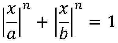
wherein: the curve shape enclosed by n-3/2 and b-1 is the preferred elliptical shape of the present invention.
The above description is only for the preferred embodiment of the present invention, and is not intended to limit the present invention, and any modifications, equivalent replacements, improvements, etc. made within the spirit and principle of the present invention should be included within the protection scope of the present invention.
Claims (7)
1. A cleaning device for glass products is characterized by comprising a cleaning main body (1), a bracket (2), a motor (10), a driving roller (9), a driven roller (4), a dryer (14), a blowing device and a transmission belt (5), the driving roller (9) and the driven roller (4) are arranged in parallel, and both ends of the driving roller and the driven roller are rotationally connected with the cleaning main body (1), the driving roller (9) is in transmission connection with the driven roller (4) through the transmission belt (5), the motor (10) is fixed on one end of the cleaning main body (1), an output shaft of the motor (10) is in transmission connection with one end of the driving roller (9) through a belt (11), the bracket (2), the blowing device and the dryer (14) are sequentially arranged on the upper side of the cleaning main body (1) along the conveying direction of the conveying belt (5) and are positioned above the conveying belt (5);
a partition plate (15) is arranged between the support (2) and the transmission belt (5), the partition plate (15) divides the space between the support (2) and the transmission belt (5) into a first cleaning chamber (23) and a second cleaning chamber (24), upper cleaning spray heads (26) are arranged at the tops of the first cleaning chamber (23) and the second cleaning chamber (24), and a channel for glass wares to pass through is arranged between the upper cleaning spray heads (26) and the upper side of the transmission belt (5);
curtain doors (3) are arranged on the sides, away from each other, of the first cleaning chamber (23) and the second cleaning chamber (24) along the length direction of the transmission belt (5);
the cleaning device is characterized in that a collecting groove (8) used for collecting cleaning liquid is arranged between the driving roller (9) and the driven roller (4), a lower cleaning spray head (7) opposite to the upper cleaning spray head (26) is arranged in the collecting groove (8), and a plurality of liquid collecting grooves (6) sequentially arranged along the length of the driving belt (5) are formed in the bottom of the collecting groove (8).
2. A cleaning device for glass products according to claim 1, characterized in that said blowing device comprises a suction fan (16), a suction device (13) and an air supply pipe (12), said suction fan (16) is arranged between said suction device (13) and said air supply pipe (12), the outlet end of said suction fan (16) is connected to said air supply pipe (12) through a pipeline, the inlet end of said suction fan (16) is connected to said suction device (13), said air supply pipe (12) is arranged on the upper side of said belt (5), said suction device (13) is arranged on the lower side of said belt (5) and is opposite to said air supply pipe (12).
3. The cleaning device for the glass products, as set forth in claim 2, characterized in that the suction device (13) comprises a suction trough body (25), a water collection trough (20) and a suction pipe (17), the suction pipe (17) is provided with a plurality of suction pipes (17) along the conveying direction of the driving belt (5) at intervals, the plurality of suction pipes (17) are all arranged in the suction trough body (25), the water collection trough (20) is arranged on one side of the suction trough body (25), one end of the suction pipe (17) extends into the water collection trough (20) and is communicated with the water collection trough (20), and one side of the water collection trough (20) far away from the suction trough body (25) is provided with an exhaust port for connecting with the inlet end of the suction fan (16).
4. A washing device for glass products according to claim 3, characterized in that the bottom of the water collection sump (20) is provided with a drain valve (19).
5. A cleaning device for glass products according to claim 3, characterized in that the suction pipe (17) is provided with a plurality of suction ports (18) at intervals in the longitudinal direction.
6. A cleaning device for glass products according to any one of claims 1-5, characterized in that the transmission belt (5) comprises a plurality of connecting rods (22) and a connecting ring (21), the plurality of connecting rods (22) are arranged around the driving roller (9) in a spaced manner from the driven roller (4), a plurality of connecting rings (21) are sleeved on the outer sides of two adjacent connecting rods (22) in a spaced manner, one end of the connecting ring (21) is fixedly connected with the rod body of one adjacent connecting rod (22), and the other end of the connecting ring (21) is movably connected with the other adjacent connecting rod (22).
7. A cleaning device for glass products according to claim 6, characterized in that the connecting ring (21) is one of an oval, a diamond or a super-oval shape.
Priority Applications (1)
| Application Number | Priority Date | Filing Date | Title |
|---|---|---|---|
| CN201920772905.9U CN210059262U (en) | 2019-05-27 | 2019-05-27 | Glass product cleaning device |
Applications Claiming Priority (1)
| Application Number | Priority Date | Filing Date | Title |
|---|---|---|---|
| CN201920772905.9U CN210059262U (en) | 2019-05-27 | 2019-05-27 | Glass product cleaning device |
Publications (1)
| Publication Number | Publication Date |
|---|---|
| CN210059262U true CN210059262U (en) | 2020-02-14 |
Family
ID=69454715
Family Applications (1)
| Application Number | Title | Priority Date | Filing Date |
|---|---|---|---|
| CN201920772905.9U Active CN210059262U (en) | 2019-05-27 | 2019-05-27 | Glass product cleaning device |
Country Status (1)
| Country | Link |
|---|---|
| CN (1) | CN210059262U (en) |
Cited By (2)
| Publication number | Priority date | Publication date | Assignee | Title |
|---|---|---|---|---|
| CN111375615A (en) * | 2020-03-27 | 2020-07-07 | 湛江国联水产开发股份有限公司 | Automatic cleaning machine for heat-insulating barrel |
| CN113465347A (en) * | 2021-07-13 | 2021-10-01 | 江西师范大学 | Air shower type rapid drying device for food vacuum packaging |
-
2019
- 2019-05-27 CN CN201920772905.9U patent/CN210059262U/en active Active
Cited By (2)
| Publication number | Priority date | Publication date | Assignee | Title |
|---|---|---|---|---|
| CN111375615A (en) * | 2020-03-27 | 2020-07-07 | 湛江国联水产开发股份有限公司 | Automatic cleaning machine for heat-insulating barrel |
| CN113465347A (en) * | 2021-07-13 | 2021-10-01 | 江西师范大学 | Air shower type rapid drying device for food vacuum packaging |
Similar Documents
| Publication | Publication Date | Title |
|---|---|---|
| CN1972624B (en) | Conveyor-type dishwasher and method for operating it | |
| CN210059262U (en) | Glass product cleaning device | |
| CN210782846U (en) | Vegetable cleaning device | |
| CN203170627U (en) | Mushroom covering sheet cleaning device | |
| CN210230931U (en) | Adjustable cleaning device for glass products | |
| CN109047121A (en) | A kind of steel belt cleaning device | |
| CN209420902U (en) | A kind of vegetable cleaning device with drain function | |
| CN205690847U (en) | Drying unit | |
| CN205686700U (en) | Cleaning equipment | |
| CN213316443U (en) | AG glass's belt cleaning device | |
| CN210676296U (en) | Glass cleaning and feeding device | |
| CN218706609U (en) | Conveying equipment | |
| CN207872679U (en) | Supersonic wave cleaning machine | |
| CN208728138U (en) | A kind of steel belt cleaning device | |
| CN212703199U (en) | Glass apron is substrate surface dust collector for coating film | |
| CN2495121Y (en) | Machine for removing hair or impurities for raw material of soft food | |
| CN212813585U (en) | Salted duck egg production is with duck egg sorting device | |
| CN213549577U (en) | Apple washing pond | |
| CN210077590U (en) | Horizontal dish washing machine | |
| CN210445464U (en) | Sucking disc stripper of cake production line | |
| CN210722959U (en) | Semiconductor wafer cleaning device | |
| CN208627929U (en) | A kind of equipment for quick washing for Chinese medicine preliminary working | |
| CN113020066A (en) | Washing medicine machine for processing traditional Chinese medicinal materials | |
| CN205686699U (en) | Flusher | |
| CN218532041U (en) | Bearing race belt cleaning device for bearing processing |
Legal Events
| Date | Code | Title | Description |
|---|---|---|---|
| GR01 | Patent grant | ||
| GR01 | Patent grant |