CN210050451U - Automatic air inlet plugging device for leakage test of automobile pipeline - Google Patents
Automatic air inlet plugging device for leakage test of automobile pipeline Download PDFInfo
- Publication number
- CN210050451U CN210050451U CN201920660478.5U CN201920660478U CN210050451U CN 210050451 U CN210050451 U CN 210050451U CN 201920660478 U CN201920660478 U CN 201920660478U CN 210050451 U CN210050451 U CN 210050451U
- Authority
- CN
- China
- Prior art keywords
- leakage test
- air inlet
- screw holes
- pipeline
- automatic
- Prior art date
- Legal status (The legal status is an assumption and is not a legal conclusion. Google has not performed a legal analysis and makes no representation as to the accuracy of the status listed.)
- Active
Links
Images


Abstract
The embodiment of the utility model discloses an automatic air inlet plugging device for automobile pipeline leakage test, in particular to the technical field of automobile pipeline accessories, which comprises an automatic air inlet plugging mechanism for leakage test; the automatic air inlet plugging mechanism for leakage testing comprises a bottom plate, an air cylinder support plate is arranged on the back face of the bottom plate, first screw holes are formed in the surface of the back face of the bottom plate and the surface of the air cylinder support plate, and a first fixing bolt is arranged inside each first screw hole. The utility model discloses a set up the automatic shutoff mechanism that admits air of leakage test, can effectual increase pipeline leakage test automatic availability factor of admitting air, can carry out effectual sealing to the pipeline through the function of cylinder, the convenience is adjusted the position of shutoff, can effectively cooperate sealedly with the pipeline, overcome the sealed in-process headspace limited and the head that causes can't seal up or can not totally seal up the phenomenon to the pipeline, prevent to cause the condition of inefficiency, improve the emergence of bad leakage test, the structure has been simplified simultaneously, and the operation of being convenient for.
Description
Technical Field
The embodiment of the utility model provides a relate to pipeline for automobile accessory technical field, concretely relates to automatic plugging device that admits air of car pipeline leakage test.
Background
In automobiles, pipelines are often used, and the pipelines are devices for conveying gas, liquid or fluid with solid particles, which are connected by pipes, pipe connectors, valves and the like, and generally, the fluid is pressurized by a blower, a compressor, a pump, a boiler and the like, flows from a high pressure part to a low pressure part of a pipeline, and can also be conveyed by the pressure or gravity of the fluid. The use of pipelines is very widespread, mainly in water supply, drainage, heating, gas supply, long-distance oil and gas delivery, agricultural irrigation, hydraulic engineering and various industrial installations.
In the production process of automobile pipelines, automobile pipelines need to be tested for leakage, pipeline types are different in size in the field production process, the reserved space of the position part where a leakage testing device is installed is not enough, the pipeline is difficult to install, the plugging position cannot be adjusted, and the pipeline cannot be effectively matched and sealed.
SUMMERY OF THE UTILITY MODEL
Therefore, the embodiment of the utility model provides an automatic plugging device that admits air of car pipeline leakage test to the position headspace of leakage test device installation among the solution prior art is not enough, and the difficulty during piping erection, shutoff position can not be adjusted, can't effectively cooperate sealed problem with the pipeline.
In order to achieve the above object, the embodiment of the present invention provides the following technical solutions: an automatic air inlet plugging device for automobile pipeline leakage test comprises an automatic air inlet plugging mechanism for leakage test;
the automatic air inlet plugging mechanism for leakage testing comprises a base plate, wherein an air cylinder support plate is arranged on the back surface of the base plate, first screw holes are formed in the back surface of the base plate and the surface of the air cylinder support plate, first fixing bolts are arranged inside the first screw holes, second screw holes are formed in the tops of the first screw holes, an air cylinder is arranged on the back surface of the air cylinder support plate, third screw holes are formed in the surface of the air cylinder, second fixing bolts are arranged inside the second screw holes and the third screw holes, an inflation connector is arranged on the front surface of the air cylinder, an air nozzle connecting hole is formed in the surface of the inflation connector, an air nozzle connector is arranged at the top of the inflation connector, a connecting pipe is arranged at the bottom of the air nozzle connector, an inflation plug is arranged on the front surface of.
Furthermore, the bottom plate surface is equipped with the fixed slot, the fixed slot bottom is equipped with the through-hole.
Furthermore, the cross sections of the bottom plate and the cylinder support plate are both square, and the bottom plate and the cylinder support plate are both made of alloy materials.
Further, first screw quantity sets up to three, second screw and third screw quantity all set up to four.
Further, first fixing bolt and first screw threaded connection, second screw and third screw all with second fixing bolt threaded connection.
Further, the cylinder output end is fixedly connected with the inflating connector, and the connecting pipe is matched with the air tap connecting hole.
The embodiment of the utility model provides a have following advantage:
through setting up the automatic shutoff mechanism that admits air of leakage testing, the availability factor that can effectual increase pipeline leakage testing automatic admission, can carry out effectual sealing to the pipeline through the function of cylinder, the convenience is adjusted the position of shutoff, can effectively cooperate sealedly with the pipeline, the head that has overcome among the sealing process reserve space limited and caused is unable to seal or can not totally sealed phenomenon to the pipeline, prevent to cause the condition of inefficiency, improve the emergence of bad leakage testing, the structure has been simplified simultaneously, the operation of being convenient for.
Drawings
In order to more clearly illustrate the embodiments of the present invention or the technical solutions in the prior art, the drawings used in the description of the embodiments or the prior art will be briefly described below. It should be apparent that the drawings in the following description are merely exemplary, and that other embodiments can be derived from the drawings provided by those of ordinary skill in the art without inventive effort.
The structure, ratio, size and the like shown in the present specification are only used for matching with the content disclosed in the specification, so as to be known and read by people familiar with the technology, and are not used for limiting the limit conditions which can be implemented by the present invention, so that the present invention has no technical essential significance, and any structure modification, ratio relationship change or size adjustment should still fall within the scope which can be covered by the technical content disclosed by the present invention without affecting the efficacy and the achievable purpose of the present invention.
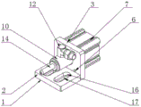
Fig. 1 is a schematic view of an overall structure of an automatic air inlet plugging device for leakage test of an automobile pipeline according to an embodiment of the present invention;
fig. 2 is an overall explosion schematic view of an automatic air inlet plugging device for leakage test of an automobile pipeline provided by an embodiment of the present invention;
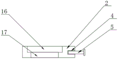
fig. 3 is a schematic structural view of a bottom plate of the automatic air inlet plugging device for leakage test of the automobile pipeline provided by the embodiment of the present invention;
fig. 4 is a schematic structural view of a cylinder support plate of the automatic air inlet plugging device for leakage test of the automobile pipeline provided by the embodiment of the present invention;
fig. 5 is a schematic perspective view of a bottom plate of the automatic air inlet plugging device for leakage test of the automobile pipeline provided by the embodiment of the present invention;
in the figure: the leakage testing automatic air inlet plugging mechanism comprises a 1 leakage testing automatic air inlet plugging mechanism, a 2 bottom plate, a 3 cylinder support plate, a 4 first screw hole, a 5 first fixing bolt, a 6 second screw hole, a 7 cylinder, a 8 third screw hole, a 9 second fixing bolt, a 10 inflation connector, a 11 air nozzle connecting hole, a 12 air nozzle connector, a 13 connecting pipe, a 14 inflation plugging, a 15 limiting ring, a 16 fixing groove and a 17 penetrating opening.
Detailed Description
The present invention is described in terms of specific embodiments, and other advantages and benefits of the present invention will become apparent to those skilled in the art from the following disclosure. Based on the embodiments in the present invention, all other embodiments obtained by a person skilled in the art without creative work belong to the protection scope of the present invention.
The automatic air inlet plugging device for the leakage test of the automobile pipeline as shown in the attached drawings 1, 2, 3, 4 and 5 comprises an automatic air inlet plugging mechanism for the leakage test 1;
the leakage-testing automatic air-intake plugging mechanism 1 comprises a bottom plate 2, an air cylinder support plate 3 is arranged on the back of the bottom plate 2, the back surface of the bottom plate 2 and the surface of the cylinder support plate 3 are both provided with a first screw hole 4, a first fixing bolt 5 is arranged inside the first screw hole 4, the top of the first screw hole 4 is provided with a second screw hole 6, the back of the cylinder support plate 3 is provided with a cylinder 7, the surface of the cylinder 7 is provided with a third screw hole 8, the second screw hole 6 and the third screw hole 8 are both internally provided with a second fixing bolt 9, the front surface of the cylinder 7 is provided with an inflation connector 10, the surface of the inflation connector 10 is provided with an air tap connecting hole 11, the top of the inflation connector 10 is provided with an air tap connector 12, the bottom of the air tap connector 12 is provided with a connecting pipe 13, the front surface of the inflatable connector 10 is provided with an inflatable plug 14, the outer side of the inflatable plug 14 is fixedly provided with a limiting ring 15, and the inflatable plug 14 is matched with the inflatable connector 10;
the surface of the bottom plate 2 is provided with a fixing groove 16, and the bottom of the fixing groove 16 is provided with a through hole 17;
the cross sections of the base plate 2 and the cylinder support plate 3 are both square, and the base plate 2 and the cylinder support plate 3 are both made of alloy materials;
the number of the first screw holes 4 is three, and the number of the second screw holes 6 and the number of the third screw holes 8 are four;
the first fixing bolt 5 is in threaded connection with the first screw hole 4, and the second screw hole 6 and the third screw hole 8 are both in threaded connection with the second fixing bolt 9;
the output end of the air cylinder 7 is fixedly connected with the inflating connector 10, and the connecting pipe 13 is matched with the air tap connecting hole 11.
The implementation mode is specifically as follows: the first screw hole 4 on the back of the base plate 2 is coincided with the first screw hole 4 on the surface of the cylinder support plate 3, then the first fixing bolt 5 is rotated to enter the first screw hole 4, so that the base plate 2 and the cylinder support plate 3 are fixed, then four third screw holes 8 arranged on the front of the cylinder 7 are coincided with four second screw holes 6 arranged on the surface of the cylinder support plate 3, then the four third screw holes 9 are rotated to enter the second screw holes 6 and the third screw holes 8, so that the cylinder 7 is connected with the cylinder support plate 3, then the inflation connector 10 is fixed with the output shaft of the cylinder 7, the inflation plug 14 is clamped with the inflation connector 10, meanwhile, the connecting pipe 13 at the bottom of the air nozzle connector 12 is clamped into the air nozzle connecting hole 11, so that the air nozzle connector 12 is communicated with the inflation connector 10, the cylinder 7 is pushed, and the cylinder 7 pushes the inflation connector 10 through the output, Aerify shutoff 14 and gas nozzle joint 12 and carry out horizontal migration, can effectual increase the availability factor that the pipeline leakage test was automatic admits air, can carry out effectual sealing to the pipeline through the function of cylinder 7, conveniently adjust the position of shutoff, can effectively cooperate sealedly with the pipeline, the head that has overcome the confined space and cause among the sealing process is unable to seal up or can not seal up completely the pipeline, prevent to cause the condition of inefficiency, improve the emergence of bad leakage test, the structure has been simplified simultaneously, and the operation of being convenient for.
The working principle of the utility model
Referring to the description figures 1, 2, 3, 4 and 5: through setting up the automatic shutoff mechanism that admits air of leakage test 1, can effectual increase pipeline leakage test automatic air intake's availability factor, can carry out effectual sealing to the pipeline through the function of cylinder 7, the convenience is adjusted the position of shutoff, can effectively cooperate with the pipeline sealed, the head that has overcome among the sealing process reserve space limited and caused can't seal or can not totally seal the phenomenon to the pipeline, prevent to cause the condition of inefficiency, improve the emergence of bad leakage test, the structure has been simplified simultaneously, and the operation of being convenient for.
Although the invention has been described in detail with respect to the general description and the specific embodiments, it will be apparent to those skilled in the art that modifications and improvements can be made based on the invention. Therefore, such modifications and improvements are intended to be within the scope of the invention as claimed.
Claims (6)
1. The utility model provides an automatic plugging device that admits air of car pipeline leak test which characterized in that: comprises a leakage test automatic air inlet plugging mechanism (1);
the leakage testing automatic air inlet plugging mechanism (1) comprises a bottom plate (2), a cylinder support plate (3) is arranged on the back of the bottom plate (2), first screw holes (4) are formed in the surface of the back of the bottom plate (2) and the surface of the cylinder support plate (3), first fixing bolts (5) are arranged inside the first screw holes (4), second screw holes (6) are formed in the top of the first screw holes (4), cylinders (7) are arranged on the back of the cylinder support plate (3), third screw holes (8) are formed in the surface of the cylinders (7), second fixing bolts (9) are arranged inside the second screw holes (6) and the third screw holes (8), an inflation connector (10) is arranged on the front face of the cylinders (7), an air nozzle connecting hole (11) is formed in the surface of the inflation connector (10), an air nozzle connector (12) is arranged on the top of the inflation connector (10), a connecting pipe (13) is arranged at the bottom, aerify connector (10) openly be equipped with and aerify shutoff (14), aerify the fixed spacing ring (15) that is equipped with in shutoff (14) outside, aerify shutoff (14) and aerify connector (10) phase-match.
2. The automatic air inlet plugging device for automobile pipeline leakage test according to claim 1, characterized in that: the surface of the bottom plate (2) is provided with a fixing groove (16), and the bottom of the fixing groove (16) is provided with a through hole (17).
3. The automatic air inlet plugging device for automobile pipeline leakage test according to claim 1, characterized in that: the cross sections of the base plate (2) and the cylinder support plate (3) are square, and the base plate (2) and the cylinder support plate (3) are made of alloy materials.
4. The automatic air inlet plugging device for automobile pipeline leakage test according to claim 1, characterized in that: the number of the first screw holes (4) is three, and the number of the second screw holes (6) and the number of the third screw holes (8) are four.
5. The automatic air inlet plugging device for automobile pipeline leakage test according to claim 4, characterized in that: first fixing bolt (5) and first screw (4) threaded connection, second screw (6) and third screw (8) all with second fixing bolt (9) threaded connection.
6. The automatic air inlet plugging device for automobile pipeline leakage test according to claim 1, characterized in that: the output end of the air cylinder (7) is fixedly connected with the inflating connector (10), and the connecting pipe (13) is matched with the air tap connecting hole (11).
Priority Applications (1)
| Application Number | Priority Date | Filing Date | Title |
|---|---|---|---|
| CN201920660478.5U CN210050451U (en) | 2019-05-09 | 2019-05-09 | Automatic air inlet plugging device for leakage test of automobile pipeline |
Applications Claiming Priority (1)
| Application Number | Priority Date | Filing Date | Title |
|---|---|---|---|
| CN201920660478.5U CN210050451U (en) | 2019-05-09 | 2019-05-09 | Automatic air inlet plugging device for leakage test of automobile pipeline |
Publications (1)
| Publication Number | Publication Date |
|---|---|
| CN210050451U true CN210050451U (en) | 2020-02-11 |
Family
ID=69382304
Family Applications (1)
| Application Number | Title | Priority Date | Filing Date |
|---|---|---|---|
| CN201920660478.5U Active CN210050451U (en) | 2019-05-09 | 2019-05-09 | Automatic air inlet plugging device for leakage test of automobile pipeline |
Country Status (1)
| Country | Link |
|---|---|
| CN (1) | CN210050451U (en) |
-
2019
- 2019-05-09 CN CN201920660478.5U patent/CN210050451U/en active Active
Similar Documents
| Publication | Publication Date | Title |
|---|---|---|
| CN210050451U (en) | Automatic air inlet plugging device for leakage test of automobile pipeline | |
| CN110701400A (en) | Quick self-sealing's pipe joint | |
| CN204115976U (en) | Diesel cylinder sleeve hydraulic type tightness measuring device | |
| CN217056471U (en) | Antifreezing valve | |
| CN212251617U (en) | Hydraulic pressure station pipeline double-lock structure | |
| CN214093489U (en) | Throttling socket joint | |
| CN211013422U (en) | Water pressure detection equipment for pipe fitting sealing performance | |
| CN209043539U (en) | A kind of pressure testing device of small dimension y-type filter body | |
| CN2436765Y (en) | Quick leaking stoppage node for pipeline | |
| CN220102479U (en) | Pipeline sealing and clamping device | |
| CN202118427U (en) | Seal device for water pressure test of pipe fitting | |
| CN219795720U (en) | Hydraulic valve block with compact structure | |
| CN220071437U (en) | Anoxic aeration system in bolting jar | |
| CN216200534U (en) | Mechanical gas cut-off valve | |
| CN216009900U (en) | Pipeline crossover sub that possesses quick installation function | |
| CN212564825U (en) | Pipeline leak protection device is used in air conditioner installation | |
| CN213576777U (en) | Liquid propane supplementing and filling device | |
| CN220540512U (en) | Pipeline connection sealing structure | |
| CN204855144U (en) | A hydrostatic test system for valve body foundry goods | |
| CN216923448U (en) | Novel warm energy-conserving pipeline connection structure that leads to | |
| CN220870314U (en) | Pipeline connection structure for hydraulic engineering | |
| CN218916681U (en) | Pressure pipeline detection device | |
| CN216111234U (en) | Ultrahigh pressure pump valve with high oil leakage prevention performance | |
| CN218094803U (en) | Convenient leak protection transmission pipeline of dismantling | |
| CN212568268U (en) | Pipe fitting socket pressure testing device |
Legal Events
| Date | Code | Title | Description |
|---|---|---|---|
| GR01 | Patent grant | ||
| GR01 | Patent grant |