CN210048571U - Industrial wastewater filtering device - Google Patents
Industrial wastewater filtering device Download PDFInfo
- Publication number
- CN210048571U CN210048571U CN201920841978.9U CN201920841978U CN210048571U CN 210048571 U CN210048571 U CN 210048571U CN 201920841978 U CN201920841978 U CN 201920841978U CN 210048571 U CN210048571 U CN 210048571U
- Authority
- CN
- China
- Prior art keywords
- box
- liquid
- crushing
- waste water
- impurity
- Prior art date
- Legal status (The legal status is an assumption and is not a legal conclusion. Google has not performed a legal analysis and makes no representation as to the accuracy of the status listed.)
- Expired - Fee Related
Links
- 238000001914 filtration Methods 0.000 title claims abstract description 36
- 239000010842 industrial wastewater Substances 0.000 title claims abstract description 20
- 239000007788 liquid Substances 0.000 claims abstract description 72
- 238000000926 separation method Methods 0.000 claims abstract description 34
- OKTJSMMVPCPJKN-UHFFFAOYSA-N Carbon Chemical compound [C] OKTJSMMVPCPJKN-UHFFFAOYSA-N 0.000 claims abstract description 31
- 239000012535 impurity Substances 0.000 claims abstract description 31
- 238000001179 sorption measurement Methods 0.000 claims abstract description 24
- 238000005520 cutting process Methods 0.000 claims abstract description 15
- 238000009826 distribution Methods 0.000 claims description 23
- 230000005540 biological transmission Effects 0.000 claims description 9
- 238000003860 storage Methods 0.000 claims description 7
- 239000010813 municipal solid waste Substances 0.000 abstract description 12
- 230000000694 effects Effects 0.000 abstract description 8
- 238000004075 wastewater filtration Methods 0.000 abstract description 2
- 238000004065 wastewater treatment Methods 0.000 abstract description 2
- 239000002351 wastewater Substances 0.000 description 58
- 239000007787 solid Substances 0.000 description 11
- 241000220317 Rosa Species 0.000 description 8
- 229910052799 carbon Inorganic materials 0.000 description 7
- XLYOFNOQVPJJNP-UHFFFAOYSA-N water Substances O XLYOFNOQVPJJNP-UHFFFAOYSA-N 0.000 description 7
- 239000002910 solid waste Substances 0.000 description 6
- 239000003344 environmental pollutant Substances 0.000 description 4
- 238000000034 method Methods 0.000 description 4
- 231100000719 pollutant Toxicity 0.000 description 4
- 239000000126 substance Substances 0.000 description 4
- 239000002699 waste material Substances 0.000 description 4
- 238000009434 installation Methods 0.000 description 3
- 239000010808 liquid waste Substances 0.000 description 3
- 238000004519 manufacturing process Methods 0.000 description 3
- 239000000463 material Substances 0.000 description 3
- 239000002893 slag Substances 0.000 description 3
- 230000005484 gravity Effects 0.000 description 2
- 238000009776 industrial production Methods 0.000 description 2
- 238000012986 modification Methods 0.000 description 2
- 230000004048 modification Effects 0.000 description 2
- 229920003023 plastic Polymers 0.000 description 2
- 239000004033 plastic Substances 0.000 description 2
- 230000009286 beneficial effect Effects 0.000 description 1
- 239000006227 byproduct Substances 0.000 description 1
- 239000000498 cooling water Substances 0.000 description 1
- 230000007423 decrease Effects 0.000 description 1
- 239000013067 intermediate product Substances 0.000 description 1
- 239000010812 mixed waste Substances 0.000 description 1
- 238000000746 purification Methods 0.000 description 1
- 238000007790 scraping Methods 0.000 description 1
- 239000010865 sewage Substances 0.000 description 1
- 239000003403 water pollutant Substances 0.000 description 1
Images

Landscapes
- Filtration Of Liquid (AREA)
- Water Treatment By Sorption (AREA)
Abstract
The utility model relates to a waste water treatment field especially relates to an industrial waste water filter equipment. The device comprises a filter box and a collecting tank, wherein an activated carbon adsorption layer is arranged in the filter box; the device comprises a liquid inlet device, an impurity crushing device and a solid-liquid separation device, wherein the liquid inlet device, the impurity crushing device, the solid-liquid separation device, a filter box and a collection tank are sequentially communicated through pipelines; impurity breaker includes broken case, first motor, pivot and cutting edge, the motor is fixed to be located outside the broken case, broken incasement portion is located in the pivot and is connected with the pivot, the cutting edge is the heliciform and is fixed in the pivot. The utility model discloses can solve the technical problem that can't separate solid-state rubbish and liquid rubbish or its separation not thorough among the waste water filtration to the scheme easily realizes, and the filter effect is showing, has realized automatic filtration, has saved the manpower, has practiced thrift the cost.
Description
Technical Field
The utility model relates to a waste water treatment field especially relates to an industrial waste water filter equipment.
Background
The industrial wastewater comprises production wastewater, production sewage and cooling water, and refers to wastewater and waste liquid in the industrial production process, wherein the wastewater and the waste liquid contain industrial production materials, intermediate products, byproducts, pollutants generated in the production process and the like which are lost along with water. Furthermore, the pollutants in the wastewater include not only dissolved and water pollutants, but also larger solid pollutants such as plastics, branches, broken stones and the like which are discharged along with the wastewater. In the existing industrial wastewater purification device, the pollutants are not distinguished and filtered, but soluble substances and insoluble substances in the wastewater are directly filtered together through an activated carbon layer. The consequence that this kind of mode leads to lies in very easily taking place the phenomenon that the wastes material piles up at the filter layer, causes the condition of jam, leads to the unable further filtration of waste water, needs the artifical solid rubbish of cleaing away of changing, wastes time and energy, inefficiency.
In the prior art, patent application No. 2017217398405, application No. 2017.12.14 discloses an industrial wastewater impurity filtering device, which uses gears, a conveyor belt and a baffle to separate solid waste in wastewater, but it does not distinguish the type of solid waste before filtering and does not perform any treatment on initial wastewater, and the filtering mode has the disadvantage that some solid waste can enter a reservoir along with a water outlet, so that the separation is not thorough.
Disclosure of Invention
In view of this, the utility model provides an industrial waste water filter equipment that can effectively make industrial waste water solid-liquid separation for the technical problem that can't separate solid-state rubbish and liquid rubbish or its separation is not thorough among the solution waste water filtration process.
The purpose of the utility model is realized through the following technical scheme:
an industrial wastewater filtering device comprises a filtering box and a collecting pool, wherein an activated carbon adsorption layer is arranged in the filtering box; the device comprises a liquid inlet device, an impurity crushing device and a solid-liquid separation device, wherein the liquid inlet device, the impurity crushing device, the solid-liquid separation device, a filter box and a collection tank are sequentially communicated through pipelines; impurity breaker includes broken case, first motor, pivot and cutting edge, the motor is fixed to be located outside the broken case, broken incasement portion is located in the pivot and is connected with the pivot, the cutting edge is the heliciform and is fixed in the pivot. The initial waste water firstly enters an impurity crushing device, the solid garbage in the waste water is crushed by the impurity crushing device, the solid garbage is smashed by a cutting edge to be crushed slag with uniform size, then the waste water is subjected to solid-liquid separation, so that single waste water without large solid garbage is obtained, and then the waste water is subjected to adsorption impurity removal treatment to obtain waste water meeting the emission standard.
Further, still include drive arrangement, drive arrangement includes driven gear, drive gear and second motor, broken case is the cylinder, the fixed cover of driven gear locates broken case lateral wall, drive gear and second motor shaft fixed connection, driven gear and drive gear meshing are connected. The purpose of adding the driving device is to enable the crushing box to rotate, so that waste water in the crushing box is centrifugally moved, solid substances attached to the waste water are concentrated on the inner wall of the crushing box due to inertia when the waste water is centrifugally moved, and the cutting efficiency of the cutting edge is improved. And, the rotation direction of crushing case is opposite with the rotation direction of cutting edge, therefore, the contact time of cutting edge and solid waste can increase, and its cutting effect can be better.
Furthermore, at least two liquid inlets are formed in the top of the crushing box, and a liquid outlet is formed in the center of the bottom of the crushing box. Because the crushing box rotates, the liquid outlet of the crushing box is positioned at the center of the rotating shaft to ensure the stability of liquid outlet.
Further, inlet means includes feed liquor pipe, liquid reserve tank, shunt tubes and connector, the liquid reserve tank is located the connector top and is fixed in broken case, the breach is seted up on the liquid reserve tank top, the feed liquor pipe passes breach and connector, shunt tubes one end and connector, the shunt tubes other end is connected with the inlet respectively and with broken case fixed connection, the connector is located directly over broken case center of rotation. Because the pivot coincidence of broken case rotation axis and first motor, consequently in order to guarantee the stability of feed liquor, set up inlet means, the utility model discloses in, inlet means's shunt tubes can rotate along with broken case together, and feed liquor pipe adopts the mode of rotating the connection with the shunt tubes to its junction is located broken case rotation axis, and consequently, broken case can not drive the removal of feed liquor pipe with the rotation of shunt tubes, thereby has guaranteed the stability of feed liquor process.
Further, the solid-liquid separation device comprises a separation box, a filter belt, a scraper and an impurity collecting box, wherein the filter belt is arranged inside the separation box and is a filter screen filter belt, the scraper is arranged at the end part of the filter belt in the transmission direction and is in contact with the filter belt, and the impurity collecting box is arranged below the scraper. The filter screen filter belt filters the waste water after carrying out the broken handle, and liquid waste water can directly pass the filter screen and enter into the separator bottom, and solid-state rubbish then can convey to the scum board department along with the filter screen filter belt, scrapes it and enters into in the magazine collecting box to realize the solid-liquid separation of waste water.
Furthermore, one end of the filter belt in the transmission direction inclines downwards, the filter belt is transmitted through a roller, and the roller is connected through a chain and driven by a driving motor to synchronously rotate. The essence of the filtering device is that the conveyor belt is replaced by the filter screen, the transmission mode of the filtering device is consistent with that of the conveyor belt, namely, the filtering device is driven by the roller and is arranged to be inclined so as to accelerate the filtering speed of the waste water by utilizing the gravity of the waste water.
Furthermore, the through hole has been seted up to rose box roof center department, still be equipped with the flow distribution plate in the rose box, flow distribution plate fixed mounting is inside the rose box, the flow distribution plate is located between rose box roof and the active carbon adsorption layer. If direct filter box that flows into from filter box roof through-hole department of waste water, then the waste water is most directly to enter into the active carbon adsorption layer center, leads to the reduction of utilization ratio to the active carbon adsorption layer to its adsorption effect also can corresponding decline.
Furthermore, the flow distribution plate is a 'V-shaped' flow distribution plate, the vertex angle edge of the 'V-shaped' flow distribution plate is positioned under the through hole, the 'V-shaped' flow distribution plate is provided with a groove in a long strip shape, and the groove runs through the 'V-shaped' flow distribution plate. Utilize the result of "type of falling V" to shunt waste water for waste water is even through the active carbon adsorption layer, and suitably reduces its velocity of flow, makes the active carbon adsorption layer have the time when enough and adsorbs the impurity in the waste water.
The utility model discloses compare in prior art's beneficial effect and be:
one, the utility model discloses utilize impurity breaker to pound solid-state material in to the waste water to pieces to handle for impurity such as plastics, billet, rubble in the waste water is all broken to the residue state of the comparatively homogeneous of size, recycles solid-liquid separation equipment and realizes the solid-liquid separation of waste water, and this application scheme is simple understandable, and easily realizes, and its filter effect is showing, has realized automatic filtering process, has saved the manpower, has practiced thrift the cost.
Two, the utility model discloses a flow distribution plate has been increased in the filter box to the flow distribution plate is simple "type of falling V", and its simple structure, but can effectual increase waste water and activated carbon adsorption layer's area of contact slow down the velocity of flow of waste water, increases waste water and activated carbon adsorption layer's contact time, thereby improves the adsorption efficiency of waste water.
Drawings
Fig. 1 is a schematic view of an overall structure of an embodiment of the present invention;
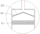
FIG. 2 is an enlarged view of a portion of FIG. 1 at A;
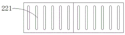
fig. 3 is a top view of the flow divider of the present invention.
Reference numerals: 1-collection pool 2-filter box 21-active carbon adsorption layer 22-flow distribution plate 221-groove 3-solid-liquid separation device 31-separation box 32-filter belt 33-impurity collection box 34-slag scraping plate 35-roller 4-impurity crushing device 41-crushing box 42-knife edge 43-rotating shaft 44-first motor 5-driving device 51-driven gear 52-driving gear 53-second motor 6-liquid inlet device 61-liquid inlet pipe 62-flow distribution pipe 63-liquid storage box 64-connecting port 65-liquid inlet.
Detailed Description
To facilitate understanding of those skilled in the art, the present invention will be described in further detail with reference to specific embodiments and drawings.
Referring to fig. 1-2, a preferred embodiment of the present invention is:
an industrial wastewater filtering device comprises a filtering box 2 and a collecting tank 1, wherein an activated carbon adsorption layer 21 is arranged in the filtering box 2; the device also comprises a liquid inlet device, an impurity crushing device 4 and a solid-liquid separation device 3, wherein the liquid inlet device, the impurity crushing device 4, the solid-liquid separation device 3, the filter box 2 and the collecting tank 1 are sequentially communicated through pipelines; the impurity crushing device 4 comprises a crushing box 41, a first motor 44, a rotating shaft 43 and a blade 42, wherein the motor is fixedly arranged outside the crushing box 41, the rotating shaft 43 is arranged inside the crushing box 41 and connected with the rotating shaft, and the blade 42 is spirally fixed on the rotating shaft 43. The initial waste water firstly enters the impurity crushing device 4, the solid garbage in the waste water is crushed by the impurity crushing device 4, the solid garbage is smashed by the cutting edge 42 to be crushed slag with uniform size, then the waste water is subjected to solid-liquid separation, so that single waste water without large solid garbage is obtained, and then the waste water is subjected to adsorption impurity removal treatment to obtain waste water meeting the emission standard.
In order to realize the possibility of installation, in the embodiment, the top plate of the crushing box 41 is a detachable structure, and the first motor 44 can be fixedly installed above the top plate of the crushing box 41 through a bracket or a cantilever, and since the rotation direction of the first motor 44 is opposite to the rotation direction of the crushing box 41, the service life of the first motor 44 and the crushing box 41 is prevented from being reduced due to friction between the two, and the two can be prevented from contacting each other during installation. Similarly, the separation tank 31, the filter tank 2, and the collection tank 1 in this embodiment have detachable top plates.
In this embodiment, the industrial wastewater filtering device further includes a driving device 5, the driving device 5 includes a driven gear 51, a driving gear 52 and a second motor 53, the crushing box 41 is cylindrical, the driven gear 51 is fixedly sleeved on the outer side wall of the crushing box 41, the driving gear 52 is fixedly connected with the rotating shaft of the second motor 53, and the driven gear 51 is meshed with the driving gear 52. The purpose of adding the driving device 5 is to make the crushing box 41 rotate, so as to make the waste water in the crushing box 41 do centrifugal motion, and when the waste water does centrifugal motion, the solid substances attached in the waste water can be concentrated on the inner wall of the crushing box 41 due to inertia, so that the cutting efficiency of the blade 42 is improved. Further, since the crushing box 41 rotates in the opposite direction to the blade 42, the contact time of the blade 42 with the solid waste is increased, and the cutting effect is improved.
Since the crushing box 41 is a rotary cylindrical box body and the first motor 44 occupies the rotation center inside thereof, a stable liquid feeding device is required in order to ensure the stability of the feeding liquid. At least two liquid inlets are arranged at the top of the crushing box 41, and a liquid outlet is arranged at the center of the bottom of the crushing box 41. The liquid outlet is located at the center of the bottom of the crushing box 41, so that the position of the liquid outlet of the crushing box 41 cannot be displaced when the crushing box rotates, and the stability of liquid outlet can be ensured only when the liquid outlet of the crushing box is located at the center of the rotating shaft.
The liquid inlet device 6 comprises a liquid inlet pipe 61, a liquid storage tank 63, a shunt pipe 62 and a connecting port 64, wherein the liquid storage tank 63 is positioned above the connecting port 64 and fixed on the crushing tank 41, a notch is formed in the top end of the liquid storage tank 63, the liquid inlet pipe 61 penetrates through the notch to be connected with the connecting port 64, one end of the shunt pipe 62 is connected with the connecting port 64, the other end of the shunt pipe 62 is respectively connected with a liquid inlet 65 and fixedly connected with the crushing tank 41, and the connecting port 64 is positioned right above the rotating center of the crushing. Because broken case 41 rotation axis coincides with first motor 44's pivot, consequently for the stability of guaranteeing the feed liquor, set up inlet means 6, the utility model discloses in, inlet means 6's shunt tubes 62 can rotate along with broken case 41 together, and feed liquor pipe 61 adopts the mode of rotating the connection with shunt tubes 62 to its junction is located broken case 41 rotation axis, and consequently, broken case 41 can not drive the removal of feed liquor pipe 61 with shunt tubes 62's rotation, thereby has guaranteed the stability of feed liquor process. In this embodiment, the liquid inlet is provided as two symmetrical connectors, and certainly, the liquid inlet may be provided as a plurality of connectors, but the connectors are always located right above the rotation center of the crushing box 41.
In this embodiment, the solid-liquid separation device 3 includes a separation box 31, a filter belt 32, a scraper 34 and a foreign matter collecting box 33, the filter belt 32 is disposed inside the separation box 31, the filter belt 32 is a filter screen filter belt 32, the scraper 34 is disposed at an end of the filter belt 32 in a transmission direction and is in contact with the filter belt 32, and the foreign matter collecting box 33 is disposed below the scraper 34. The filter screen filter belt 32 filters the waste water after the crushing treatment, the liquid waste water can directly pass through the filter screen and enter the bottom of the separation box 31, and the solid waste can be conveyed to the scraper 34 along with the filter screen filter belt 32 and is scraped down to enter the magazine collecting box, so that the solid-liquid separation of the waste water is realized. The side wall of the separation box 31 is provided with a notch for realizing the installation of the filter screen and the filter belt 32 and the removal of impurities. And the separation box 31 is also provided with a liquid inlet hole and a liquid outlet hole for the transmission and transfer of the waste water.
One end of the filter belt 32 in the transmission direction inclines downwards, the filter belt 32 is transmitted through a roller 35, and the roller 35 is connected through a chain and driven by a driving motor to rotate synchronously. The essence of the filtering device is that the conveyor belt is replaced by a filter screen, the transmission mode of the filter belt is consistent with that of the conveyor belt, namely, the filter belt is driven by the roller 35, and the filter belt is inclined so as to accelerate the filtering speed of the waste water by utilizing the gravity of the waste water.
The through-hole has been seted up to 2 roof centers on rose box, still is equipped with flow distribution plate 22 in rose box 2, and flow distribution plate 22 fixed mounting is inside rose box 2, and flow distribution plate 22 is located between 2 roof of rose box and the active carbon adsorption layer 21. If the waste water directly flows into the filter box 2 from the through hole of the top plate of the filter box 2, most of the waste water directly enters the center of the activated carbon adsorption layer 21, so that the utilization rate of the activated carbon adsorption layer 21 is reduced, and the adsorption effect of the waste water is correspondingly reduced.
The flow distribution plate 22 is an inverted V-shaped flow distribution plate 22, the vertex angle edge of the inverted V-shaped flow distribution plate 22 is positioned right below the through hole, the inverted V-shaped flow distribution plate 22 is provided with a strip-shaped groove 221, and the groove 221 penetrates through the inverted V-shaped flow distribution plate 22. The waste water is divided by using the result of the inverted V shape, so that the waste water uniformly passes through the activated carbon adsorption layer 21, and the water flow speed is properly reduced, so that the activated carbon adsorption layer 21 has enough time to adsorb impurities in the waste water.
The utility model discloses a theory of operation: waste water enters from the liquid inlet pipe and flows into the crushing box 41 through the shunt pipe, the first motor 44 drives the blade 42 to rotate and the second motor 53 drives the crushing box 41 to rotate inside the crushing box 41, solid impurities in the waste water are smashed through the matching effect of the rotation of the first motor and the second motor in opposite directions, the smashed mixed waste water flows into the solid-liquid separation device 3 to separate single liquid waste water, the adsorption treatment on the waste water is realized through the filtering effect of the filter box 2, and therefore the waste water meeting the discharge or utilization standard is obtained.
While the invention has been described in conjunction with the specific embodiments set forth above, it is evident that many alternatives, modifications, and variations will be apparent to those skilled in the art in light of the foregoing description. Accordingly, it is intended to embrace all such alternatives, modifications, and variations that fall within the spirit and scope of the appended claims.
Claims (8)
1. An industrial wastewater filtering device comprises a filtering box and a collecting pool, wherein an activated carbon adsorption layer is arranged in the filtering box; the device is characterized by further comprising a liquid inlet device, an impurity crushing device and a solid-liquid separation device, wherein the liquid inlet device, the impurity crushing device, the solid-liquid separation device, the filter box and the collecting tank are sequentially communicated through pipelines; impurity breaker includes broken case, first motor, pivot and cutting edge, the motor is fixed to be located outside the broken case, broken incasement portion is located in the pivot and is connected with the pivot, the cutting edge is the heliciform and is fixed in the pivot.
2. The industrial wastewater filtering device according to claim 1, further comprising a driving device, wherein the driving device comprises a driven gear, a driving gear and a second motor, the crushing box is cylindrical, the driven gear is fixedly sleeved on the outer side wall of the crushing box, the driving gear is fixedly connected with the rotating shaft of the second motor, and the driven gear is meshed with the driving gear.
3. The industrial wastewater filtering device as claimed in claim 2, wherein the top of the crushing box is provided with at least two liquid inlets, and the center of the bottom of the crushing box is provided with one liquid outlet.
4. The industrial wastewater filtering device according to claim 1, wherein the liquid inlet device comprises a liquid inlet pipe, a liquid storage tank, a flow dividing pipe and a connecting port, the liquid storage tank is positioned above the connecting port and fixed on the crushing tank, a notch is formed in the top end of the liquid storage tank, the liquid inlet pipe passes through the notch and is connected with the connecting port, one end of the flow dividing pipe is connected with the connecting port, the other end of the flow dividing pipe is respectively connected with the liquid inlet and is fixedly connected with the crushing tank, and the connecting port is positioned right above the rotation center of the crushing tank.
5. The industrial wastewater filtering device according to claim 1, wherein the solid-liquid separation device comprises a separation box, a filter belt, a scraper and an impurity collecting box, the filter belt is arranged inside the separation box, the filter belt is a filter screen filter belt, the scraper is arranged at the end part of the filter belt in the transmission direction and is in contact with the filter belt, and the impurity collecting box is arranged below the scraper.
6. The industrial wastewater filtering apparatus according to claim 5, wherein one end of the filter belt in the transmission direction is inclined downward, the filter belt is driven by rollers, and the rollers are connected by a chain and driven by a driving motor to rotate synchronously.
7. The industrial wastewater filtering device according to claim 1, wherein a through hole is formed in the center of the top plate of the filtering box, a flow distribution plate is further arranged in the filtering box, the flow distribution plate is fixedly arranged in the filtering box, and the flow distribution plate is located between the top plate of the filtering box and the activated carbon adsorption layer.
8. The industrial wastewater filtering device according to claim 7, wherein the splitter plate is an inverted V-shaped splitter plate, the vertex angle edge of the inverted V-shaped splitter plate is located right below the through hole, and the inverted V-shaped splitter plate is provided with an elongated groove which penetrates through the inverted V-shaped splitter plate.
Priority Applications (1)
| Application Number | Priority Date | Filing Date | Title |
|---|---|---|---|
| CN201920841978.9U CN210048571U (en) | 2019-06-05 | 2019-06-05 | Industrial wastewater filtering device |
Applications Claiming Priority (1)
| Application Number | Priority Date | Filing Date | Title |
|---|---|---|---|
| CN201920841978.9U CN210048571U (en) | 2019-06-05 | 2019-06-05 | Industrial wastewater filtering device |
Publications (1)
| Publication Number | Publication Date |
|---|---|
| CN210048571U true CN210048571U (en) | 2020-02-11 |
Family
ID=69397135
Family Applications (1)
| Application Number | Title | Priority Date | Filing Date |
|---|---|---|---|
| CN201920841978.9U Expired - Fee Related CN210048571U (en) | 2019-06-05 | 2019-06-05 | Industrial wastewater filtering device |
Country Status (1)
| Country | Link |
|---|---|
| CN (1) | CN210048571U (en) |
Cited By (1)
| Publication number | Priority date | Publication date | Assignee | Title |
|---|---|---|---|---|
| WO2022052356A1 (en) * | 2020-09-11 | 2022-03-17 | 山东理工职业学院 | Hepa filter applied to industrial circulating water treatment |
-
2019
- 2019-06-05 CN CN201920841978.9U patent/CN210048571U/en not_active Expired - Fee Related
Cited By (1)
| Publication number | Priority date | Publication date | Assignee | Title |
|---|---|---|---|---|
| WO2022052356A1 (en) * | 2020-09-11 | 2022-03-17 | 山东理工职业学院 | Hepa filter applied to industrial circulating water treatment |
Similar Documents
| Publication | Publication Date | Title |
|---|---|---|
| CN214209671U (en) | Sludge discharge device for sewage treatment | |
| CN212894393U (en) | Oil field drilling sludge treatment system | |
| CN114560576A (en) | Self-cleaning circulation purification equipment for coal mining mine water | |
| CN210048571U (en) | Industrial wastewater filtering device | |
| CN210764763U (en) | Sewage treatment device | |
| CN211302304U (en) | Chemical solid-liquid garbage separation device | |
| CN111905887A (en) | Intelligent organic garbage treatment device and method | |
| CN217988643U (en) | Mud-water separation device | |
| CN215048849U (en) | Novel shallow air flotation equipment | |
| CN108911381A (en) | Rainwater purification apparatus | |
| CN210131436U (en) | Kitchen deslagging and water filtering device | |
| CN112661294A (en) | Urban sewage recovery processing system | |
| CN213699047U (en) | Environment-friendly sewage treatment system | |
| CN219291651U (en) | Stable and cleanable sweeps stable separator | |
| CN220633311U (en) | Kitchen garbage collection and treatment device | |
| CN211644872U (en) | Reaction, precipitation and filtration integrated machine for cleaning wastewater | |
| CN220951375U (en) | Slurry balance shield tunnel muddy water treatment device | |
| CN220070945U (en) | Grating separation device for oily waste liquid | |
| CN216537321U (en) | Purifier for waste water treatment | |
| CN216223292U (en) | Coal-containing wastewater pretreatment device for thermal power plant | |
| CN218421225U (en) | Plate-and-frame filter press with mud cake fixing mechanism | |
| CN213295147U (en) | Flocculation mixing arrangement for sludge treatment | |
| CN207811416U (en) | A kind of cuttings liquid recovery system | |
| CN212269707U (en) | A preprocessing device for carbon tetrachloride gets rid of | |
| CN115448499B (en) | Underground working face water sump |
Legal Events
| Date | Code | Title | Description |
|---|---|---|---|
| GR01 | Patent grant | ||
| GR01 | Patent grant | ||
| CF01 | Termination of patent right due to non-payment of annual fee |
Granted publication date: 20200211 |
|
| CF01 | Termination of patent right due to non-payment of annual fee |