CN210031499U - Bridge drainage system - Google Patents
Bridge drainage system Download PDFInfo
- Publication number
- CN210031499U CN210031499U CN201920746524.3U CN201920746524U CN210031499U CN 210031499 U CN210031499 U CN 210031499U CN 201920746524 U CN201920746524 U CN 201920746524U CN 210031499 U CN210031499 U CN 210031499U
- Authority
- CN
- China
- Prior art keywords
- water
- pipe
- drainage
- water collecting
- bridge
- Prior art date
- Legal status (The legal status is an assumption and is not a legal conclusion. Google has not performed a legal analysis and makes no representation as to the accuracy of the status listed.)
- Expired - Fee Related
Links
Images
Classifications
-
- Y—GENERAL TAGGING OF NEW TECHNOLOGICAL DEVELOPMENTS; GENERAL TAGGING OF CROSS-SECTIONAL TECHNOLOGIES SPANNING OVER SEVERAL SECTIONS OF THE IPC; TECHNICAL SUBJECTS COVERED BY FORMER USPC CROSS-REFERENCE ART COLLECTIONS [XRACs] AND DIGESTS
- Y02—TECHNOLOGIES OR APPLICATIONS FOR MITIGATION OR ADAPTATION AGAINST CLIMATE CHANGE
- Y02A—TECHNOLOGIES FOR ADAPTATION TO CLIMATE CHANGE
- Y02A20/00—Water conservation; Efficient water supply; Efficient water use
- Y02A20/20—Controlling water pollution; Waste water treatment
Landscapes
- Sewage (AREA)
Abstract
The utility model relates to the technical field of bridges, in particular to a bridge drainage system, which comprises a bridge body, a guardrail and a roadbed surface, wherein drainage grooves are arranged on two sides of the roadbed surface, the upper surface and the bottom surface of each drainage groove are respectively detachably connected with a filter screen I and a filter screen II, and the aperture of the filter screen I is larger than that of the filter screen II; the bottom of the drainage groove is connected with a drainage pipe; the water drainage pipe is respectively connected with the water collecting tank I and the water collecting tank II; and a water pump is arranged at the bottom of the water collecting tank II and is respectively connected with a water inlet pipe and a water outlet pipe, and the top of the water outlet pipe is connected with a rotary nozzle. The utility model can filter the garbage or sand and stone with different sizes, and is convenient to clean; set up the catch basin respectively in the top of bridge body and below both sides and collect the rainwater, partly rainwater can be used for cooling off the road surface in the high temperature, and another part rainwater can be collected and utilized.
Description
Technical Field
The utility model relates to a bridge technical field, in particular to bridge drainage system.
Background
In the construction process of a bridge, in order to prevent the surface of the bridge from being washed and eroded by rainwater, a drainage system needs to be arranged in the bridge, and drainage grooves are generally arranged on two sides of the lower terrain of the road surface of the bridge in the existing bridge drainage, filter screens are arranged on the drainage grooves, and then rainwater is drained into a river or collected through drainage pipes. Usually, only one filter screen is arranged on the drainage grooves on two sides, and the filter screens are not arranged in other places, so when the diameter of the filter screen is small, drainage is not timely under the condition of large rain force, and water accumulation is easily caused; when the aperture of the filter screen is set to be larger, garbage with smaller volume enters a drainage pipeline and is easy to block after being accumulated for a long time; and the rainwater is collected by using one collecting tank, and the collected rainwater has single purpose.
Disclosure of Invention
The utility model overcomes prior art is not enough, provides a bridge drainage system, carries out twice filtration to the rainwater, adopts 2 collecting ponds to carry out the rainwater and collects, makes the rainwater have the multiple use.
In order to solve the technical problem, the utility model discloses a realize through following technical scheme: a bridge drainage system comprises a bridge body, guardrails and a roadbed surface, wherein the roadbed surface is connected above the bridge body, the guardrails are fixed on two sides of the roadbed surface, the roadbed surface is of a structure with a high middle part and two low sides, drainage grooves are formed in two sides of the roadbed surface, the upper surface and the bottom surface of each drainage groove are detachably connected with a filter screen I and a filter screen II respectively, and the aperture of the filter screen I is larger than that of the filter screen II; the bottom of the drainage groove is connected with a drainage pipe, and the drainage pipe is fixed on the outer wall of the bridge body; the lower end of the drain pipe extends into the water collecting tank I; the top of the bridge body is provided with a water collecting cavity, and the water collecting cavity comprises buffer pools with the bottoms inclined downwards and a water collecting pool II positioned between the two buffer pools; a water pump is arranged at the bottom of the water collecting tank II and is respectively connected with a water inlet pipe and a water outlet pipe, the upper end of the water outlet pipe penetrates through a road base surface, and the top of the water outlet pipe is connected with a rotary nozzle; one side of the drain pipe close to the buffer pool is communicated with a branch pipe, and the branch pipe is obliquely arranged along the bottom of the buffer pool; and the upper part of the water collecting tank II is communicated with an overflow pipe, and the overflow pipe is downwards inclined and communicated to a drain pipe.
Preferably, the drainage channel penetrates through a road base surface.
Preferably, the bottom of the buffer tank is inclined downwards by an angle of 5-10 degrees.
As a preferred scheme, a slag removal opening is formed in the side face of the bottom of the water collecting tank II.
Preferably, the downward inclination angle of the overflow pipe is 20-30 degrees.
As the preferred scheme, I top in collecting basin is equipped with the access hole, and bottom one side is equipped with the scarfing cinder mouth.
As preferred scheme, the water pump has two, and the symmetric distribution is in the both sides of II bottoms on the catch basin, the outlet pipe is located the one side that the guardrail was kept away from to the water drainage tank.
Compared with the prior art, the beneficial effects of the utility model are that: the utility model discloses set up the filter screen that the aperture is different at the top and the bottom of water drainage tank respectively, the filter screen I aperture at top is relatively great, also can in time drain off when the rainfall is great, and rubbish, grit etc. that leak down from filter screen I can be filtered with filter screen II that the aperture is less, can dismantle the filter screen and conveniently clear up rubbish, grit etc. and conveniently change in the water drainage tank; set up the catch basin respectively in the top of bridge body and below both sides and collect the rainwater, partly rainwater can be used for cooling off the road surface in the high temperature, and another part rainwater can be collected and utilized.
Drawings
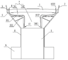
Fig. 1 is a schematic view of the overall structure of the present invention.
In the figure: 1 bridge body, 2 guardrails, 3 way base planes, 4 water drainage tank, 5 filter screens I, 6 filter screens II, 7 collecting chamber, 8 drain pipes, 9 catch basin I, 10 water pump, 1001 inlet tube, 1002 outlet pipes, 1003 rotating nozzle.
Detailed Description
The invention will be described in further detail with reference to the following detailed description and accompanying drawings:
as shown in fig. 1, a bridge drainage system comprises a bridge body 1, guardrails 2 and a roadbed 3, wherein the roadbed 3 is connected above the bridge body 1, the guardrails 2 are fixed on two sides of the roadbed 3, and the roadbed 3 is of a structure with a high middle part and low two sides, so that drainage is facilitated; both sides of a roadbed surface 3 are provided with through drainage grooves 4, the upper surfaces of the drainage grooves 4 are detachably connected with filter screens I5, the bottom surfaces of the drainage grooves 4 are detachably connected with filter screens II 6, the pore diameters of the filter screens I5 are larger than those of the filter screens II 6, water can be drained timely when the rain force is large, garbage, gravel and the like leaking from the filter screens I5 can be filtered by the filter screens II 6 with smaller pore diameters, and the detachable filter screens are convenient for cleaning the garbage, gravel and the like in the drainage grooves and replacing the filter screens; the bottom of the drainage groove 4 is connected with a drainage pipe 8, the drainage pipe 8 is fixed on the outer wall of the bridge body 1, and the lower end of the drainage pipe 8 extends into a water collecting tank I9; the top of the bridge body 1 is provided with a water collecting cavity 7, and the water collecting cavity 7 comprises buffer pools 701 with the bottoms inclined downwards by 5-10 degrees and a water collecting pool II 702 positioned between the two buffer pools 701; 2 water pumps 10 are symmetrically arranged on two sides of the bottom of the water collecting pool II 702, the water pumps 10 are connected with a power supply and a PLC control system, and the PLC control system is also connected with a liquid level sensor positioned in the water collecting pool II 702 and a temperature sensor positioned on the ground; the water pump 10 is respectively connected with a water inlet pipe 1001 and a water outlet pipe 1002, the upper end of the water outlet pipe 1002 penetrates through the roadbed surface 3 and is positioned on one side of the drainage groove 4 away from the guardrail 2, the top of the water outlet pipe is connected with a rotary nozzle 1003, and when the weather is hot, the water stored in the water collecting tank II 702 can be used for cooling the roadbed; a slag removal port is formed in the side face of the bottom of the water collecting tank II 702, is normally closed, and can be opened periodically for slag removal; one side of the drain pipe 8, which is close to the buffer tank 701, is communicated with a branch pipe 801, the branch pipe 801 is obliquely arranged along the bottom of the buffer tank 701, the inclination angle is 5-10 degrees, and rainwater can be conveniently shunted from the branch pipe 801 to enter a water collecting tank II 702; the upper part of the water collecting pool II 702 is communicated with an overflow pipe 802, the overflow pipe 802 inclines downwards by 20-30 degrees and is communicated with a drain pipe 8, and when water in the water collecting pool II 702 reaches the height of the overflow pipe 802, the water overflows from the overflow pipe 802 and enters a water collecting pool I9; the top of catch basin I9 is equipped with the access hole, and bottom one side is equipped with the scarfing cinder mouth, and the scarfing cinder mouth is usually closed, opens when needing the scarfing cinder and is used for the scarfing cinder.
When raining, rainwater flows to the drainage grooves 4 on two sides of the roadbed surface 3 with lower topography, and is filtered by the filter screen I5 with larger aperture, so that garbage with larger volume is blocked outside, rainwater, garbage with smaller volume and some gravels enter the drainage grooves 4, most of the gravels are filtered by the filter screen II, and the rainwater and a small amount of gravels enter the water collecting pool I9 and the water collecting pool II 702 respectively through the drainage pipe 8; when the temperature sensor on the ground detects that the ambient temperature is higher than the set temperature, the PLC control system controls the water pump 10 to work, and when the liquid level detects that the water level is lower than the set water level or the temperature is lower than the set temperature, the water pump 10 stops working.
The utility model discloses technical characteristics that have not described can be through or adopt prior art to realize, no longer describe here, and of course, above-mentioned embodiment is not right the utility model discloses a restriction, the utility model discloses also not only be limited to above-mentioned embodiment, ordinary skilled person in this technical field is in the utility model discloses a change, modification, interpolation or replacement made in the essential scope also should fall into the utility model discloses a protection scope.
Claims (7)
1. The utility model provides a bridge drainage system, includes bridge body (1), guardrail (2) and roadbed face (3), bridge body (1) top is connected with roadbed face (3), roadbed face (3) both sides are fixed with guardrail (2), roadbed face (3) are the structure that the high both sides in middle part are low, open the both sides of roadbed face (3) has water drainage tank (4), its characterized in that: the upper surface and the bottom surface of the drainage tank (4) are respectively detachably connected with a filter screen I (5) and a filter screen II (6), and the aperture of the filter screen I (5) is larger than that of the filter screen II (6); the bottom of the drainage groove (4) is connected with a drainage pipe (8), and the drainage pipe (8) is fixed on the outer wall of the bridge body (1); the lower end of the drain pipe (8) extends into the water collecting tank I (9); the top of the bridge body (1) is provided with a water collecting cavity (7), and the water collecting cavity (7) comprises buffer pools (701) with the bottoms inclined downwards and a water collecting pool II (702) positioned between the two buffer pools (701); a water pump (10) is arranged at the bottom of the water collecting tank II (702), the water pump (10) is respectively connected with a water inlet pipe (1001) and a water outlet pipe (1002), the upper end of the water outlet pipe (1002) penetrates through the roadbed surface (3), and the top of the water outlet pipe is connected with a rotary nozzle (1003); one side of the drain pipe (8) close to the buffer pool (701) is communicated with a branch pipe (801), and the branch pipe (801) is obliquely arranged along the bottom of the buffer pool (701); the upper part of the water collecting tank II (702) is communicated with an overflow pipe (802), and the overflow pipe (802) inclines downwards and is communicated to a drain pipe (8).
2. A bridge drainage system as claimed in claim 1, wherein: the drainage channel (4) penetrates through the roadbed surface (3).
3. A bridge drainage system as claimed in claim 1, wherein: the downward inclination angle of the bottom of the buffer pool (701) is 5-10 degrees.
4. A bridge drainage system as claimed in claim 1, wherein: and a slag removal opening is formed in the side surface of the bottom of the water collecting tank II (702).
5. A bridge drainage system as claimed in claim 1, wherein: the downward inclination angle of the overflow pipe (802) is 20-30 degrees.
6. A bridge drainage system as claimed in claim 1, wherein: the top of the water collecting tank I (9) is provided with an access hole, and one side of the bottom of the water collecting tank I is provided with a slag removal hole.
7. A bridge drainage system as claimed in claim 1, wherein: the water pumps (10) are symmetrically distributed on two sides of the bottom of the water collecting tank II (702), and the water outlet pipe (1002) is located on one side, away from the guardrail (2), of the water draining groove (4).
Priority Applications (1)
| Application Number | Priority Date | Filing Date | Title |
|---|---|---|---|
| CN201920746524.3U CN210031499U (en) | 2019-05-23 | 2019-05-23 | Bridge drainage system |
Applications Claiming Priority (1)
| Application Number | Priority Date | Filing Date | Title |
|---|---|---|---|
| CN201920746524.3U CN210031499U (en) | 2019-05-23 | 2019-05-23 | Bridge drainage system |
Publications (1)
| Publication Number | Publication Date |
|---|---|
| CN210031499U true CN210031499U (en) | 2020-02-07 |
Family
ID=69367438
Family Applications (1)
| Application Number | Title | Priority Date | Filing Date |
|---|---|---|---|
| CN201920746524.3U Expired - Fee Related CN210031499U (en) | 2019-05-23 | 2019-05-23 | Bridge drainage system |
Country Status (1)
| Country | Link |
|---|---|
| CN (1) | CN210031499U (en) |
Cited By (1)
| Publication number | Priority date | Publication date | Assignee | Title |
|---|---|---|---|---|
| CN112538990A (en) * | 2020-11-28 | 2021-03-23 | 肃木丁建筑设计咨询(深圳)有限公司 | View platform convenient to drainage |
-
2019
- 2019-05-23 CN CN201920746524.3U patent/CN210031499U/en not_active Expired - Fee Related
Cited By (1)
| Publication number | Priority date | Publication date | Assignee | Title |
|---|---|---|---|---|
| CN112538990A (en) * | 2020-11-28 | 2021-03-23 | 肃木丁建筑设计咨询(深圳)有限公司 | View platform convenient to drainage |
Similar Documents
| Publication | Publication Date | Title |
|---|---|---|
| CN205636879U (en) | System's device is collected, is purified and utilize to overpass rainwater | |
| CN107805990A (en) | A kind of rainwater on road surface excludes purification self-cleaning system and its installation method | |
| CN108612172A (en) | A kind of sponge urban rainwater collection irrigation system | |
| CN203514395U (en) | Impurity discarding system auto-adaptive to water level variation to extract clean rainwater | |
| CN106638917B (en) | Split type rainwater recycling, storing and adjusting system and construction method thereof | |
| CN110984351A (en) | Automatic diverging device of initial stage rainwater | |
| CN108797756A (en) | Rain penetration purifies savings system in a kind of landscape planting | |
| CN107401209A (en) | Rainwater-collecting purifies and is used for the equipment afforested in a kind of park | |
| CN207538151U (en) | Concave herbaceous field and the well lid for concave herbaceous field | |
| CN106638882A (en) | Rainwater collecting and utilizing system | |
| CN206109974U (en) | Bridge drainage system | |
| CN209353440U (en) | Road rain water suitable for sponge city stores heat-extraction system | |
| CN210031499U (en) | Bridge drainage system | |
| CN211897679U (en) | Novel sponge urban road system | |
| TWM446788U (en) | An automatic hydraulicrainwater reclaim device | |
| CN206554213U (en) | A kind of anti-waterlogging drainage system in city | |
| CN205357488U (en) | A irrigation equipment for roof greening lawn | |
| CN108056004A (en) | A kind of overpass rainwater catchment system irrigation system | |
| CN202122876U (en) | Rainwater recycling system | |
| CN107514045A (en) | Concave herbaceous field | |
| CN201952879U (en) | Cutoff apparatus used in municipal rainwater pipe network for cutting off the rainwater flow of the initial period | |
| CN207794243U (en) | Sunk type greenery patches reverse osmosis layer automatic flushing device in a kind of sponge city | |
| CN215906695U (en) | Hydraulic engineering protects bearing structure with ecological bank protection | |
| CN206815504U (en) | A kind of self-cleaning storm detention tank based on water-jet | |
| CN211547958U (en) | Sewage separation and recovery device for wetland park construction |
Legal Events
| Date | Code | Title | Description |
|---|---|---|---|
| GR01 | Patent grant | ||
| GR01 | Patent grant | ||
| CF01 | Termination of patent right due to non-payment of annual fee |
Granted publication date: 20200207 Termination date: 20210523 |
|
| CF01 | Termination of patent right due to non-payment of annual fee |