CN210026162U - Secondary ejection mechanism - Google Patents
Secondary ejection mechanism Download PDFInfo
- Publication number
- CN210026162U CN210026162U CN201920823521.5U CN201920823521U CN210026162U CN 210026162 U CN210026162 U CN 210026162U CN 201920823521 U CN201920823521 U CN 201920823521U CN 210026162 U CN210026162 U CN 210026162U
- Authority
- CN
- China
- Prior art keywords
- secondary ejection
- guide
- plate
- lower template
- ejector
- Prior art date
- Legal status (The legal status is an assumption and is not a legal conclusion. Google has not performed a legal analysis and makes no representation as to the accuracy of the status listed.)
- Active
Links
Images


Abstract
The utility model discloses a secondary ejection mechanism, including thimble board, guide pin bushing, guide pillar, lower template seat, through-hole, ejector pin, supporting shoe, layer board, spacing dabber embedding post, spring, push rod, the ejecting push rod stopper of secondary, groove, guide block, lower bolster, the ejecting movable block of secondary, spacing dabber, ejecting with glide plane, drawing of patterns inclined plane, linkage draw-in groove, the embedded guide pin bushing of thimble board, establish the guide pillar in the guide pin bushing, the lower extreme threaded connection of guide pillar is on the lower template seat, two through-holes are seted up to the lower template seat, be connected to thimble board bottom by the bolt after the ejector pin passes the through-hole. In this way, the utility model provides a secondary ejection mechanism through optimizing the mould design structure, replaces the hydro-cylinder with secondary ejection mechanism and pulls out the core mechanism, and the mould manufacturing cost that has significantly reduced has reduced the mould size, and the mould after reducing can be produced on 250T double-colored machines, and product manufacturing cost reduces and because little board screw rod diameter is little, and the product quality is more stable.
Description
Technical Field
The utility model relates to a mould field especially relates to a secondary ejection mechanism.
Background
Injection molding, which means that a material melted by heat is injected into a mold cavity from high pressure, and a formed product is obtained after cooling and solidification. The parts of the formed product which need to be smoothly separated from the die and can not be separated from the vertical direction need to be separated by a slide block, an inclined top or an oil cylinder inclined slide block and the like, and then the product is ejected out of the die cavity by an ejector rod.
During actual production, for example, a product has an oblique column, the oblique column is separated from the conventional die structure by adopting the oblique sliding block of the oil cylinder, and the oblique sliding block of the oil cylinder has the following defects: the product structure requires a mold to be designed with an oil cylinder core pulling mechanism, so that the mold structure is complex and the manufacturing cost is high; the large size of the die requires a large-scale injection molding machine (a two-color machine with more than 360T) for production, the production cost is high, the product quality is not fixed, and the rubber material is easy to carbonize in the screw.
SUMMERY OF THE UTILITY MODEL
The utility model discloses the main technical problem who solves provides a secondary ejection mechanism, through optimizing mould design structure, replaces the hydro-cylinder with secondary ejection mechanism and pulls out the core mechanism, and the mould manufacturing cost that has significantly reduced has reduced the mould size, and the mould after reducing can be produced on 250T double-colored machines, and product manufacturing cost reduces and because little board screw rod diameter is little, and the product quality is more stable.
In order to solve the technical problem, the utility model discloses a technical scheme be: the secondary ejection mechanism comprises an ejector plate, a guide sleeve, a guide pillar, a lower template seat, through holes, an ejector rod, support blocks, a support plate, a limiting mandrel embedded pillar, a spring, a push rod, a secondary ejection push rod limiting block, a groove, a guide block, a lower template, a secondary ejection movable block, a limiting mandrel, an ejection sliding surface, a demolding inclined surface and a linkage clamping groove, wherein the guide sleeve is embedded in the ejector plate, the guide pillar is arranged in the guide sleeve, the lower end of the guide pillar is connected to the lower template seat in a threaded manner, the lower template seat is provided with two through holes, the ejector rod penetrates through the through holes and then is connected to the bottom of the ejector plate through bolts, the two support blocks are respectively arranged on two sides of the ejector plate on the lower template seat through bolts, the support plate frame is arranged on the support blocks, the ejector plate is supported and connected with the lower template through the limiting mandrel embedded pillar, the limiting mandrel embedded pillar, the ejector pin plate is characterized in that a pair of push rods which are axially parallel to the springs are arranged on two opposite side faces of the ejector pin plate, secondary ejection push rod limiting blocks are fixedly mounted on the two opposite side faces of the supporting plate, grooves are formed in the secondary ejection push rod limiting blocks, the push rods are inserted into the grooves, the guide blocks are embedded into the side faces of the lower template through bolts, the secondary ejection movable blocks stretch and slightly move in the secondary ejection push rod limiting blocks through limiting mandrels with springs, ejection sliding faces are arranged on two sides of each groove, demolding inclined faces matched with the secondary ejection movable blocks are arranged at the upper ends of the ejection sliding faces, and linkage clamping grooves matched with the secondary ejection movable blocks are formed in the lower ends of the ejection sliding faces.
In a preferred embodiment of the present invention, the ejector plate is provided with a plurality of buffer pads fixed by bolts on both sides.
In a preferred embodiment of the present invention, the ejector plate is provided with a through hole, a support pillar is disposed in the through hole, a lower end of the support pillar is fixed to the lower die plate holder by a bolt, and an upper end of the support pillar is supported on the lower surface of the support plate.
The utility model has the advantages that: the utility model provides a pair of secondary ejection mechanism through optimizing mould design structure, replaces the hydro-cylinder with secondary ejection mechanism and pulls out the mechanism of core, and the mould manufacturing cost that has significantly reduced has reduced the mould size, and the mould after reducing can be produced on 250T double-colored machines, and product manufacturing cost reduces and because little board screw rod diameter is little, and the product quality is more stable.
Drawings
In order to more clearly illustrate the technical solutions of the embodiments of the present invention, the drawings used in the description of the embodiments are briefly introduced below, and it is obvious that the drawings in the following description are only some embodiments of the present invention, and for those skilled in the art, other drawings can be obtained without inventive work, wherein:
fig. 1 is a structural diagram of a preferred embodiment of a secondary ejection mechanism of the present invention;
fig. 2 is a structural diagram of a preferred embodiment of a secondary ejection mechanism of the present invention;
fig. 3 is a structural diagram of a preferred embodiment of a secondary ejection mechanism of the present invention;
fig. 4 is a structural diagram of a preferred embodiment of a secondary ejection mechanism of the present invention;
fig. 5 is a structural diagram of a preferred embodiment of a secondary ejection mechanism of the present invention;
fig. 6 is a structural diagram of a preferred embodiment of a secondary ejection mechanism of the present invention;
fig. 7 is a structural diagram of a preferred embodiment of a secondary ejection mechanism of the present invention.
Detailed Description
The technical solutions in the embodiments of the present invention will be described clearly and completely below, and it should be apparent that the described embodiments are only some embodiments of the present invention, but not all embodiments. Based on the embodiments in the present invention, all other embodiments obtained by a person skilled in the art without creative efforts belong to the protection scope of the present invention.
As shown in fig. 1-7, the embodiment of the present invention includes:
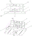
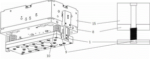
a secondary ejection mechanism comprises an ejector plate 1, a guide sleeve 2, a guide post 3, a lower plate seat 4, through holes 5, an ejector rod 6, a supporting block 7, a supporting plate 8, a limiting mandrel embedded column 9, a spring 10, a push rod 11, a secondary ejection push rod limiting block 12, a groove 13, a guide block 14, a lower plate 15, a secondary ejection movable block 16, a limiting mandrel 17, an ejection sliding surface 18, a demoulding inclined surface 19 and a linkage clamping groove 20, wherein the guide sleeve 2 is embedded in the ejector plate 1, the guide post 3 is arranged in the guide sleeve 2, the lower end of the guide post 3 is in threaded connection with the lower plate seat 4, the lower plate seat 4 is provided with two through holes 5, the ejector rod 6 is connected to the bottom of the ejector plate 1 through bolts after penetrating through the through holes 5, the two supporting blocks 7 are respectively installed on two sides of the ejector plate 1 on the lower plate seat 4 through bolts, the supporting plate 8 is erected on the supporting block 7, the ejector plate 1 is supported, a spring 10 is sleeved on the limit mandrel embedded column 9, two ends of the spring 10 are respectively connected with the supporting plate 8 and the ejector plate 1, a pair of push rods 11 which are parallel to the axial direction of the spring 10 are arranged on two opposite side surfaces of the ejector plate 1, two opposite side surfaces of the supporting plate 8 are fixedly provided with secondary ejection push rod limiting blocks 12, the secondary ejection push rod limiting blocks 12 are provided with grooves 13, the push rod 11 is inserted into the slot 13, the guide block 14 is embedded into the side surface of the lower template 15 through a bolt, the secondary ejection movable block 16 extends and slightly moves in the secondary ejection push rod limiting block 12 through a limiting mandrel 17 with a spring 10, sliding surfaces 18 for ejection are arranged on two sides of the groove 13, a demoulding inclined surface 19 matched with the secondary ejection movable block 16 is arranged at the upper end of the sliding surface 18 for ejection, and a linkage clamping groove 20 matched with the secondary ejection movable block 16 is arranged at the lower end of the ejection sliding surface 18.
Wherein, a plurality of buffer gaskets 101 fixed by bolts are arranged on both sides of the ejector plate 1.
Further, a through hole 5 is formed in the ejector plate 1, a support column 105 is arranged in the through hole 5, the lower end of the support column 105 is fixed on the lower die plate seat 4 through a bolt, and the upper end of the support column 105 is supported on the lower surface of the supporting plate 8.
The working principle of secondary ejection is as follows: the ejector rod 6 is driven to move upwards along the vertical direction, the ejector rod 6 drives the ejector plate 1 to move upwards, the ejector plate 1 drives the push rod 11 to move upwards, the upper end of the push rod 11 drives the secondary ejection movable block 16 to move upwards, and the secondary ejection movable block 16 drives the lower template 15 to move upwards, so that the lower template 15 is separated from the supporting plate 8 to complete secondary ejection.
When the secondary ejection movable block 16 rises to the demolding inclined surface 19, the secondary ejection movable block 16 is extruded into the guide block 14 by the demolding inclined surface 19, and after the secondary ejection movable block 16 is completely extruded into the guide block 14, the push rod 11 is completely separated from the secondary ejection movable block 16, so that the lower template 15 falls back to the original state under the action of gravity.
To sum up, the utility model provides a secondary ejection mechanism through optimizing the mould design structure, replaces the hydro-cylinder with secondary ejection mechanism and pulls out the core mechanism, and the mould manufacturing cost that has significantly reduced has reduced the mould size, and the mould after reducing can be produced on 250T double-colored machines, and product manufacturing cost reduces and because little board screw rod diameter is little, and the product quality is more stable.
The above only is the embodiment of the present invention, not limiting the patent scope of the present invention, all of which utilize the equivalent structure or equivalent flow transformation made by the content of the specification of the present invention, or directly or indirectly applied to other related technical fields, all included in the same way in the patent protection scope of the present invention.
Claims (3)
1. A secondary ejection mechanism is characterized by comprising an ejector plate, a guide sleeve, a guide pillar, a lower template base, through holes, an ejector rod, a supporting block, a supporting plate, a limiting core shaft embedded pillar, a spring, a push rod, a secondary ejection push rod limiting block, a groove, a guide block, a lower template, a secondary ejection movable block, a limiting core shaft, an ejection sliding surface, a demolding inclined surface and a linkage clamping groove, wherein the ejector plate is embedded with the guide sleeve, the guide pillar is arranged in the guide sleeve, the lower end of the guide pillar is connected to the lower template base in a threaded manner, the lower template base is provided with two through holes, the ejector rod penetrates through the through holes and then is connected to the bottom of the ejector plate through bolts, the two supporting blocks are respectively installed on two sides of the ejector plate on the lower template base through bolts, the supporting plate is arranged on the supporting block, the ejector plate is supported and connected with the lower, the two ends of the spring are respectively connected with the supporting plate and the ejector plate, a pair of push rods which are parallel to the axial direction of the spring are arranged on two opposite side faces of the ejector plate, secondary ejection push rod limiting blocks are fixedly arranged on the two opposite side faces of the supporting plate, grooves are formed in the secondary ejection push rod limiting blocks, the push rods are inserted into the grooves, the guide blocks are embedded into the side faces of the lower template through bolts, the secondary ejection movable blocks stretch and slightly move in the secondary ejection push rod limiting blocks through limiting mandrels with springs, ejection sliding faces are arranged on two sides of the grooves, demolding inclined faces matched with the secondary ejection movable blocks are arranged at the upper ends of the ejection sliding faces, and linkage clamping grooves matched with the secondary ejection movable blocks are formed in the lower ends of the ejection sliding.
2. The secondary ejection mechanism of claim 1, wherein the ejector plate is provided on both sides with a plurality of cushioning pads secured by bolts.
3. The secondary ejection mechanism of claim 1, wherein the ejector plate is provided with a through hole, a support column is arranged in the through hole, the lower end of the support column is fixed on the lower die plate seat through a bolt, and the upper end of the support column is supported on the lower surface of the supporting plate.
Priority Applications (1)
| Application Number | Priority Date | Filing Date | Title |
|---|---|---|---|
| CN201920823521.5U CN210026162U (en) | 2019-06-03 | 2019-06-03 | Secondary ejection mechanism |
Applications Claiming Priority (1)
| Application Number | Priority Date | Filing Date | Title |
|---|---|---|---|
| CN201920823521.5U CN210026162U (en) | 2019-06-03 | 2019-06-03 | Secondary ejection mechanism |
Publications (1)
| Publication Number | Publication Date |
|---|---|
| CN210026162U true CN210026162U (en) | 2020-02-07 |
Family
ID=69346210
Family Applications (1)
| Application Number | Title | Priority Date | Filing Date |
|---|---|---|---|
| CN201920823521.5U Active CN210026162U (en) | 2019-06-03 | 2019-06-03 | Secondary ejection mechanism |
Country Status (1)
| Country | Link |
|---|---|
| CN (1) | CN210026162U (en) |
Cited By (1)
| Publication number | Priority date | Publication date | Assignee | Title |
|---|---|---|---|---|
| CN115946308A (en) * | 2023-03-10 | 2023-04-11 | 宁波语方模塑有限公司 | Double ejection mechanism for injection mold and injection mold |
-
2019
- 2019-06-03 CN CN201920823521.5U patent/CN210026162U/en active Active
Cited By (1)
| Publication number | Priority date | Publication date | Assignee | Title |
|---|---|---|---|---|
| CN115946308A (en) * | 2023-03-10 | 2023-04-11 | 宁波语方模塑有限公司 | Double ejection mechanism for injection mold and injection mold |
Similar Documents
| Publication | Publication Date | Title |
|---|---|---|
| CN210026162U (en) | Secondary ejection mechanism | |
| CN208020655U (en) | Side core-pulling injection mold with groove plastic | |
| CN203236673U (en) | Die for secondary ejection | |
| CN2759758Y (en) | Two-stage side-wise loose-core device of plastic mould | |
| CN201240038Y (en) | Bumper mould without push board or mould foot | |
| CN210047005U (en) | Structure for converting diagonal line position into horizontal line position | |
| CN203472053U (en) | Injection mold of tubular parts | |
| CN210436509U (en) | Flexible demolding and core-pulling injection mold for bridge-crossing pipe fitting | |
| CN212498715U (en) | Injection mold with replaceable insert | |
| CN109848395B (en) | Indirect liquid forging device and clamping mechanism thereof | |
| CN209454082U (en) | A kind of leather shoes punching press injection mold | |
| CN203901794U (en) | Multi-step mold frame used for full-automatic dry powder hydraulic machine | |
| CN207290762U (en) | A kind of injection mold of oblique pusher | |
| CN220784777U (en) | Quick press-fit device for plastic product mold | |
| CN212764538U (en) | Injection mold for outer water tank of water purifier | |
| CN219360166U (en) | Plastic mould frame with connection structure | |
| CN209521230U (en) | The maximized ejector mechanism die mould bases of knockout press | |
| CN219311882U (en) | High-impact PVC pipe fitting die | |
| CN214726236U (en) | Movable template cylinder guide structure for mold locking mechanism of injection molding machine | |
| CN205167408U (en) | Injection mold is released to two -way order of spring | |
| CN210940311U (en) | Thread back-off core-pulling die | |
| CN210477632U (en) | Cooling type high-precision plastic mould | |
| CN220428996U (en) | Composite material thermosetting forming die | |
| CN212498801U (en) | Quick ejection mechanism of injection mold | |
| CN210632756U (en) | Stamping part forming die |
Legal Events
| Date | Code | Title | Description |
|---|---|---|---|
| GR01 | Patent grant | ||
| GR01 | Patent grant | ||
| CP03 | Change of name, title or address |
Address after: 214000 No. 3, Xingye Road, Luoshe Town, Huishan District, Wuxi City, Jiangsu Province Patentee after: Wuxi Jinxin precision mould Co.,Ltd. Address before: 215500 building 4, No. 8, Taizhou Road, Yushan high tech Industrial Park, Changshu, Suzhou, Jiangsu Patentee before: Suzhou Jianbang Precision Mould Co.,Ltd. |
|
| CP03 | Change of name, title or address |