CN210025857U - Auxiliary device for building interior decoration - Google Patents
Auxiliary device for building interior decoration Download PDFInfo
- Publication number
- CN210025857U CN210025857U CN201920658064.9U CN201920658064U CN210025857U CN 210025857 U CN210025857 U CN 210025857U CN 201920658064 U CN201920658064 U CN 201920658064U CN 210025857 U CN210025857 U CN 210025857U
- Authority
- CN
- China
- Prior art keywords
- fixedly connected
- mount
- rod
- interior decoration
- auxiliary device
- Prior art date
- Legal status (The legal status is an assumption and is not a legal conclusion. Google has not performed a legal analysis and makes no representation as to the accuracy of the status listed.)
- Expired - Fee Related
Links
Images


Abstract
The utility model relates to a building technical field just discloses an auxiliary device is used to building interior decoration, the on-line screen storage device comprises a base, the equal fixedly connected with mount in both sides at base top, two bottom movable sleeve between the mount is equipped with the lead screw, the one end of lead screw extends to the outside and the fixedly connected with knob of mount, and the movable block has been cup jointed in the activity on the lead screw. This auxiliary device for building interior decoration, through the cooperation of the corresponding laser rangefinder receiver in position on laser rangefinder transmitter on the mount and the clamp plate, the workman is when needs carry out the cutting of corresponding size to panel and ceramic tile etc, through setting for cutting size, utilize controller control electric push rod to push away the clamp plate and remove corresponding distance can, and is simple and convenient, it is accurate to find the distance, and after the range finding, the side of clamp plate is in on the cutting line, the user only need along the clamp plate bottom the edge cut can, the cutting is accurate, and is convenient, the difficult deviation that appears.
Description
Technical Field
The utility model relates to a building technical field specifically is an auxiliary device is used to building interior decoration.
Background
The interior decoration of a building comprises room design, decoration, furniture arrangement and various small decoration points, is heavier than the decoration construction inside the building, not only comprises long-term continuous decoration after the building is placed in during the decoration design construction period, but also gradually builds the concept of light decoration and heavy decoration, and in the interior decoration process of the building, a cutting device for cutting plates, ceramic tiles and the like is required to be used.
However, current cutting device for interior decoration does not all possess the material to the cutting, for example panel and ceramic tile etc. carry out the device of fixing, in current interior decoration in-process, the workman master need draw a line on the ceramic tile that needs cut through measuring device, after drawing a line, utilize the hand to compress tightly fixedly to the one end of ceramic tile, reuse another hand, handheld cutting device cuts the position that the ceramic tile was drawn a line, or compress tightly the ceramic tile through other people's assistance, another one person holds cutting device and cuts, not only inconvenient, and the measuring degree of accuracy, the degree of accuracy of cutting is all relatively poor, and ceramic tile itself is breakable, produce vibrations easily in cutting process and breakage, the material has been wasted, the fitment progress has been influenced.
SUMMERY OF THE UTILITY MODEL
Aiming at the defects of the prior art, the utility model provides an auxiliary device for building interior decoration, which has the advantages of convenient use, simple and accurate measurement and shock absorption, solves the problem that the existing cutting device for interior decoration does not have a device for fixing cut materials, such as plates, ceramic tiles and the like, in the existing interior decoration process, a worker needs to draw lines on the ceramic tiles needing to be cut through the measuring device, after the lines are drawn, one end of the ceramic tiles is pressed and fixed by hands, the other hand is reused, the part of the ceramic tiles drawn by the hand-held cutting device is cut, or the ceramic tiles are pressed by the assistance of other people, the other person holds the cutting device to cut, which is not only inconvenient, but also has poor measuring accuracy, the cutting accuracy is poor, the ceramic tiles are fragile, and the ceramic tiles are easy to vibrate and break easily in the cutting process, wasting materials and influencing the decoration progress.
The utility model provides a following technical scheme: an auxiliary device for building interior decoration comprises a base, wherein fixing frames are fixedly connected to two sides of the top of the base, a lead screw is movably sleeved at the bottom between the two fixing frames, one end of the lead screw extends to the outside of the fixing frames and is fixedly connected with a knob, a moving block is movably sleeved on the lead screw, a clamping seat is arranged at the top of the moving block, a controller is fixedly installed at the top of the side surface of one fixing frame, a laser ranging emitter is arranged at one side of one fixing frame away from the controller, four fixing frames are provided, a connecting frame is fixedly connected to the top between the two fixing frames positioned at one side of the base, a motor is fixedly installed at one side of the top of the connecting frame, a threaded rod is fixedly sleeved on an output shaft of the motor, the bottom of the threaded rod is movably sleeved with the top of the base, a, the utility model discloses a laser ranging device, including base, bracing piece, fixed plate, fixed rod, telescopic link, spring, fixed cover, the middle part fixed mounting of fixed plate side has the cylinder, the output movable sleeve of cylinder is equipped with the piston rod, the one end movable sleeve of piston rod is equipped with the loop bar, the movable sleeve is equipped with the spring on the loop bar, fixed cover is equipped with the gag lever post that is located lead screw one side on the mount, the one end fixedly connected with connecting plate of loop bar, the connecting plate is the L type, and the top fixedly connected with electric push rod of connecting plate side, the one end fixedly connected with clamp plate of electric push rod, the side of clamp plate be equipped with the mount on the corresponding laser.
Preferably, the quantity of mount has four, four the mount divide into two sets ofly and every group quantity has two, and is a set of bottom that is close to between the mount of link is equipped with the board that supports for lead screw and gag lever post, another group be equipped with the board that supports for controller, laser range finding transmitter equally between the mount, it is a set of be close to the board height value on the mount of link one side is less than the height value of another group mount upper plate.
Preferably, the controller is electrically connected with the motor, the laser ranging emitter, the air cylinder, the electric push rod and the laser ranging receiver.
Preferably, one end of the spring is fixedly connected with one end of the piston rod, and the other end of the spring is fixedly connected with the side face of the connecting plate.
Preferably, the side surfaces of the plates or the tiles and the like placed on the clamping seat are movably connected with the side surface of the connecting plate, the top portions of the plates or the tiles and the like placed on the clamping seat are movably connected with the bottom portion of the pressing plate, and the clamping seat is made of flexible materials such as rubber.
Compared with the prior art, the utility model discloses possess following beneficial effect:
1. this building is auxiliary device for interior decoration, adjust the distance between the cassette through rotating the knob, thereby be convenient for not panel and the ceramic tile of equidimension carry out the joint and place, it descends to drive the fixed plate through starter motor, thereby it descends to drive the fixed clamp plate of electricity push rod one end on the link, it is fixed to carry out the vertical direction chucking to panel etc. on the cassette, the restart cylinder, it is fixed to carry out the chucking of horizontal direction to panel or ceramic tile etc. of placing on the connecting plate that drives loop bar one end to the cassette, it is convenient to cut it, and utilize the cooperation of loop bar and spring, and the cassette of rubber material, be convenient for in cutting process, carry out the shock attenuation on level and the vertical direction to fixed panel or ceramic tile, thereby avoid it to take place cracked and wasted the problem of material in cutting process.
2. This auxiliary device for building interior decoration, through the cooperation of the corresponding laser rangefinder receiver in position on laser rangefinder transmitter on the mount and the clamp plate, the workman is when needs carry out the cutting of corresponding size to panel and ceramic tile etc, through setting for cutting size, utilize controller control electric push rod to push away the clamp plate and remove corresponding distance can, and is simple and convenient, it is accurate to find the distance, and after the range finding, the side of clamp plate is in on the cutting line, the user only need along the clamp plate bottom the edge cut can, the cutting is accurate, and is convenient, the difficult deviation that appears.
Drawings
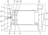
FIG. 1 is a schematic structural view of the present invention;
FIG. 2 is a top view of the present invention;
fig. 3 is a schematic view of the structural supporting rod of the present invention.
In the figure: 1. a base; 2. a fixed mount; 3. a screw rod; 4. a knob; 5. a moving block; 6. a card holder; 7. a controller; 8. a laser ranging transmitter; 9. a connecting frame; 10. a motor; 11. a threaded rod; 12. a support bar; 13. a fixing plate; 14. a cylinder; 15. a piston rod; 16. a loop bar; 17. a spring; 18. a limiting rod; 19. a connecting plate; 20. an electric push rod; 21. pressing a plate; 22. laser range finding receiver.
Detailed Description
The technical solutions in the embodiments of the present invention will be described clearly and completely with reference to the accompanying drawings in the embodiments of the present invention, and it is obvious that the described embodiments are only some embodiments of the present invention, not all embodiments. Based on the embodiments in the present invention, all other embodiments obtained by a person skilled in the art without creative work belong to the protection scope of the present invention.
Referring to fig. 1-3, an auxiliary device for interior decoration of a building comprises a base 1, wherein two sides of the top of the base 1 are fixedly connected with four fixing frames 2, the number of the fixing frames 2 is two, the four fixing frames 2 are divided into two groups, the number of each group is two, a plate for supporting a screw rod 3 and a limiting rod 18 is arranged at the bottom between the fixing frames 2 close to a connecting frame 9, a plate for supporting a controller 7 and a laser distance measuring emitter 8 is also arranged between the fixing frames 2 of the other group, the height value of the plate on the fixing frame 2 at one side close to the connecting frame 9 is smaller than that of the plate on the fixing frame 2 of the other group, the screw rod 3 is movably sleeved at the bottom between the two fixing frames 2, one end of the screw rod 3 extends to the outside of the fixing frame 2 and is fixedly connected with a knob 4, a movable block 5 is movably sleeved, the side surface of a plate or a ceramic tile and the like placed on the clamping seat 6 is movably connected with the side surface of the connecting plate 19, the top part of the plate or the ceramic tile and the like placed on the clamping seat 6 is movably connected with the bottom part of the pressing plate 21, the clamping seat 6 is made of flexible materials such as rubber, a controller 7 is fixedly installed at the top part of the side surface of a fixing frame 2, the controller 7 is electrically connected with a motor 10, a laser ranging emitter 8, an air cylinder 14, an electric push rod 20 and a laser ranging receiver 22, the laser ranging emitter 8 is arranged at one side of the fixing frame 2 far away from the controller 7, the number of the fixing frames 2 is four, a connecting frame 9 is fixedly connected at the top part between the two fixing frames 2 at one side of the base 1, the motor 10 is fixedly installed at one side of the top part of the connecting frame 9, a threaded rod 11 is fixedly sleeved on an output shaft of the, thereby improving the stability of the fixed plate 13 when lifting, the bottom of the threaded rod 11 is movably sleeved with the top of the base 1, one side of the bottom of the connecting frame 9 is fixedly sleeved with the supporting rod 12, the bottom of the supporting rod 12 is fixedly connected with one side of the top of the base 1, the fixed plate 13 is movably sleeved on the supporting rod 12, the middle part of the side surface of the fixed plate 13 is fixedly provided with the air cylinder 14, the output end of the air cylinder 14 is movably sleeved with the piston rod 15, one end of the piston rod 15 is movably sleeved with the loop bar 16, the loop bar 16 is movably sleeved with the spring 17, one end of the spring 17 is fixedly connected with one end of the piston rod 15, the other end of the spring 17 is fixedly connected with the side surface of the connecting plate 19, the cooperation of the loop bar 16 and the spring 17 and the clamping seat 6 made of rubber material are utilized, so as to facilitate the horizontal, avoid it to take place cracked in cutting process, fixed cover is equipped with the gag lever post 18 that is located 3 one sides of lead screw on the mount 2, gag lever post 18 cup joints with the one end activity of movable block 5, utilize gag lever post 18 to support and spacing movable block 5, thereby improve the stability when movable block 5 rotates along with lead screw 3 and removes, the one end fixedly connected with connecting plate 19 of loop bar 16, connecting plate 19 is the L type, and the top fixedly connected with electric push rod 20 of connecting plate 19 side, the one end fixedly connected with clamp plate 21 of electric push rod 20, the side of clamp plate 21 is equipped with and fixes 2 on the mount 8 corresponding laser rangefinder receiver 22 in position of laser rangefinder transmitter.
The working principle is as follows: firstly, according to the size of the plate or the ceramic tile, after the knob 4 is rotated to drive the screw rod 3 to rotate, the clamping seats 6 on the moving block 5 are driven to move simultaneously in opposite or opposite directions, the space between the clamping seats 6 is adjusted, so that the plate or the ceramic tile and the like with different sizes can be clamped and placed conveniently, then, the threaded rod 11 is driven to rotate by the starting motor 10, the fixing plate 13 is driven to descend, so that the pressing plate 21 fixed at one end of the electric push rod 20 on the connecting plate 19 is driven to descend, the plate and the like on the clamping seats 6 are clamped and fixed in the vertical direction, the air cylinder 14 is started again, the connecting plate 19 at one end of the sleeve rod 16 is driven to clamp and fix the plate or the ceramic tile and the like placed on the clamping seats 6 in the horizontal direction, so that the plate or the ceramic tile and the like can be cut conveniently, the clamping seats 6 made of rubber materials are, finally, through the cooperation of the laser range finding receiver 22 of position correspondence on the laser range finding transmitter 8 on the mount 2 and the clamp plate 21, the workman is when needs carry out the cutting of corresponding size to panel and ceramic tile etc. through setting for cutting size, utilize controller 7 control electric push rod 20 promote clamp plate 21 remove corresponding distance can, and is simple and convenient, and the range finding is accurate, and after the range finding, the side of clamp plate 21 is in on the cutting line, the user only need cut along the edge of clamp plate 21 bottom, can.
Although embodiments of the present invention have been shown and described, it will be appreciated by those skilled in the art that changes, modifications, substitutions and alterations can be made in these embodiments without departing from the principles and spirit of the invention, the scope of which is defined in the appended claims and their equivalents.
Claims (5)
1. The utility model provides an auxiliary device for building interior decoration, includes base (1), its characterized in that: the two sides of the top of the base (1) are fixedly connected with fixing frames (2), a lead screw (3) is movably sleeved at the bottom between the two fixing frames (2), one end of the lead screw (3) extends to the outer part of the fixing frame (2) and is fixedly connected with a knob (4), a moving block (5) is movably sleeved on the lead screw (3), a clamping seat (6) is arranged at the top of the moving block (5), a controller (7) is fixedly arranged at the top of the side surface of one fixing frame (2), a laser ranging emitter (8) is arranged at one side of one fixing frame (2) far away from the controller (7), the number of the fixing frames (2) is four, a connecting frame (9) is fixedly connected at the top between the two fixing frames (2) positioned at one side of the base (1), and a motor (10) is fixedly arranged at one side of the top of, the screw rod (11) is fixedly sleeved on an output shaft of the motor (10), the bottom of the screw rod (11) is movably sleeved with the top of the base (1), a support rod (12) is fixedly sleeved on one side of the bottom of the connecting frame (9), the bottom of the support rod (12) is fixedly connected with one side of the top of the base (1), a fixing plate (13) is movably sleeved on the support rod (12), a cylinder (14) is fixedly installed at the middle of the side surface of the fixing plate (13), a piston rod (15) is movably sleeved on the output end of the cylinder (14), a sleeve rod (16) is movably sleeved on one end of the piston rod (15), a spring (17) is movably sleeved on the sleeve rod (16), a limiting rod (18) positioned on one side of the screw rod (3) is fixedly sleeved on the fixing frame (2), and a connecting plate (19) is fixedly connected with one end, the connecting plate (19) is L-shaped, the top of the side surface of the connecting plate (19) is fixedly connected with an electric push rod (20), one end of the electric push rod (20) is fixedly connected with a pressing plate (21), and the side surface of the pressing plate (21) is provided with a laser ranging receiver (22) corresponding to the position of the laser ranging transmitter (8) on the fixing frame (2).
2. An auxiliary device for interior decoration of a building as claimed in claim 1, wherein: four mount (2) divide into two sets ofly and every group quantity has two, and is a set of bottom between mount (2) is equipped with carries out the board that supports for lead screw (3) and gag lever post (18), another group be equipped with the board that supports for controller (7), laser range finding transmitter (8) equally between mount (2), and is a set of be close to the board height value on link (9) one side mount (2) and be less than the height value of another set of mount (2) upper plate.
3. An auxiliary device for interior decoration of a building as claimed in claim 1, wherein: the controller (7) is electrically connected with the motor (10), the laser ranging emitter (8), the air cylinder (14), the electric push rod (20) and the laser ranging receiver (22).
4. An auxiliary device for interior decoration of a building as claimed in claim 1, wherein: one end of the spring (17) is fixedly connected with one end of the piston rod (15), and the other end of the spring (17) is fixedly connected with the side face of the connecting plate (19).
5. An auxiliary device for interior decoration of a building as claimed in claim 1, wherein: the side surfaces of plates or tiles and the like placed on the clamping seat (6) are movably connected with the side surfaces of the connecting plates (19), the top portions of the plates or tiles and the like placed on the clamping seat (6) are movably connected with the bottom portion of the pressing plate (21), and the clamping seat (6) is made of flexible materials such as rubber.
Priority Applications (1)
| Application Number | Priority Date | Filing Date | Title |
|---|---|---|---|
| CN201920658064.9U CN210025857U (en) | 2019-05-08 | 2019-05-08 | Auxiliary device for building interior decoration |
Applications Claiming Priority (1)
| Application Number | Priority Date | Filing Date | Title |
|---|---|---|---|
| CN201920658064.9U CN210025857U (en) | 2019-05-08 | 2019-05-08 | Auxiliary device for building interior decoration |
Publications (1)
| Publication Number | Publication Date |
|---|---|
| CN210025857U true CN210025857U (en) | 2020-02-07 |
Family
ID=69364249
Family Applications (1)
| Application Number | Title | Priority Date | Filing Date |
|---|---|---|---|
| CN201920658064.9U Expired - Fee Related CN210025857U (en) | 2019-05-08 | 2019-05-08 | Auxiliary device for building interior decoration |
Country Status (1)
| Country | Link |
|---|---|
| CN (1) | CN210025857U (en) |
Cited By (1)
| Publication number | Priority date | Publication date | Assignee | Title |
|---|---|---|---|---|
| CN114453949A (en) * | 2022-02-09 | 2022-05-10 | 江苏索亚建筑装饰新材料有限公司 | Positioning and cutting device and method for decorative plate with measurable edge distance |
-
2019
- 2019-05-08 CN CN201920658064.9U patent/CN210025857U/en not_active Expired - Fee Related
Cited By (1)
| Publication number | Priority date | Publication date | Assignee | Title |
|---|---|---|---|---|
| CN114453949A (en) * | 2022-02-09 | 2022-05-10 | 江苏索亚建筑装饰新材料有限公司 | Positioning and cutting device and method for decorative plate with measurable edge distance |
Similar Documents
| Publication | Publication Date | Title |
|---|---|---|
| CN210025857U (en) | Auxiliary device for building interior decoration | |
| CN214721451U (en) | Automatic laser-beam welding machine of optic fibre | |
| CN210261555U (en) | Glass processing operation panel | |
| CN209775201U (en) | Ceramic tile side cut device | |
| CN209904381U (en) | Limiting tool for automatic root carving machine | |
| CN215588189U (en) | High-precision positioning cutting tool for cutting of automatic equipment case | |
| CN211072855U (en) | Tool setting device of numerical control machine tool | |
| CN210171992U (en) | Silica gel removing device | |
| CN211806649U (en) | A wooden decoration material cutting device for interior decoration | |
| CN210969226U (en) | Fixed-length cutting device for plate production | |
| CN113084681A (en) | Curtain architectural decoration is with hanging stone material integration system of processing futilely | |
| CN209334883U (en) | A kind of wire cutting machine | |
| CN113580384A (en) | A auxiliary device for building interior decoration | |
| CN215559873U (en) | Jig for cutting inner circle of optical glass | |
| CN206029606U (en) | Automatic device of measuring of dust absorption formula piece sword thickness | |
| CN218017622U (en) | Turnover mechanism for polishing optical lens for telescope | |
| CN220903504U (en) | Fitment material cutting device that fitment was used | |
| CN220144209U (en) | Cleaning clamp for automobile parts | |
| CN216227198U (en) | Cutting device is used in processing of air spring piston rod | |
| CN209157937U (en) | A kind of polished edges of stones bench device | |
| CN215433182U (en) | Chamfering device for aluminum part machining | |
| CN218488021U (en) | Precision grinding apparatus is with grinding mold core processingequipment | |
| CN219153013U (en) | Panel processingequipment for building interior decoration | |
| CN211053134U (en) | Numerical control machining clamp for inner frame of aviation light guide plate | |
| CN214666509U (en) | Surveying and mapping device for indoor design |
Legal Events
| Date | Code | Title | Description |
|---|---|---|---|
| GR01 | Patent grant | ||
| CF01 | Termination of patent right due to non-payment of annual fee | ||
| CF01 | Termination of patent right due to non-payment of annual fee |
Granted publication date: 20200207 |