CN210021832U - Floating ball control device with high liquid medicine mixing degree for copper ore mining - Google Patents
Floating ball control device with high liquid medicine mixing degree for copper ore mining Download PDFInfo
- Publication number
- CN210021832U CN210021832U CN201920403066.3U CN201920403066U CN210021832U CN 210021832 U CN210021832 U CN 210021832U CN 201920403066 U CN201920403066 U CN 201920403066U CN 210021832 U CN210021832 U CN 210021832U
- Authority
- CN
- China
- Prior art keywords
- main body
- pipe
- liquid medicine
- transmission shaft
- floating ball
- Prior art date
- Legal status (The legal status is an assumption and is not a legal conclusion. Google has not performed a legal analysis and makes no representation as to the accuracy of the status listed.)
- Active
Links
Images


Abstract
The utility model relates to a floater control device with high liquid medicine mixing degree for copper mine exploitation, which comprises a main body, a discharge pipe, a control valve and at least two feeding devices, wherein the main body is cuboid in shape, the discharge pipe is communicated with the bottom of the main body, the discharge pipe is vertical to the plane where the bottom of the main body is located, the control valve is arranged on the discharge pipe, the feeding devices are uniformly arranged at the top of the main body, the feeding devices comprise a high-pressure tank, a feeding pipe and a floating ball valve, the high-pressure tank is arranged at the top of the main body, the bottom of the high-pressure tank is communicated with the main body through the feeding pipe, the feeding pipe is parallel to the discharge pipe, the floating ball valve is positioned in the main body, the floating ball valve is arranged on the feeding pipe, a stirring mechanism is arranged in the main body, the floating ball control device with high liquid medicine mixing degree for copper, the deviation between the liquid medicine discharged from the discharge pipe and the set proportion is reduced.
Description
Technical Field
The utility model relates to a mineral exploitation equipment field, in particular to a floater controlling means that liquid medicine degree of mixing is high for copper mine exploitation.
Background
Mineral resource exploitation refers to exploitation of solid metal and non-metal mineral deposits, wherein an automatic control floating ball valve box is one of common devices in copper ore exploitation, and the automatic control floating ball valve box mainly functions in adding a flotation reagent in a copper ore flotation system according to a certain proportion, so that the automatic control floating ball valve box is widely applied due to simple operation and strong reliability.
The existing automatic control floating ball valve box is used in the process that after a medicine is added into the floating ball valve box, the medicine liquid is different in mobility and limited in mixing effect, so that the proportion of the mixed medicine liquid entering the flotation equipment is still different from the expected proportion, and the practicability is reduced.
SUMMERY OF THE UTILITY MODEL
The to-be-solved technical problem of the utility model is: in order to overcome the defects of the prior art, the floating ball control device for the copper ore mining is high in liquid medicine mixing degree.
The utility model provides a technical scheme that its technical problem adopted is: the floating ball control device comprises a main body, a discharge pipe, a control valve and at least two feeding devices, wherein the main body is cuboid in shape, the discharge pipe is communicated with the bottom of the main body, the discharge pipe is perpendicular to a plane where the bottom of the main body is located, the control valve is arranged on the discharge pipe, the feeding devices are uniformly arranged at the top of the main body, each feeding device comprises a high-pressure box, a feeding pipe and a floating ball valve, the high-pressure box is arranged at the top of the main body, the bottom of the high-pressure box is communicated with the main body through the feeding pipe, the feeding pipe is parallel to the discharge pipe, the floating ball valve is located in the main body, the floating ball valve is mounted on the feeding pipe, and a stirring mechanism is arranged in the main body;
rabbling mechanism includes paddle, transmission shaft, hob, supporting component and two stirring rods, transmission shaft and hob all with the coaxial setting of discharging pipe, the one end at the transmission shaft is installed to the paddle, the other end at the transmission shaft is fixed to the hob, the paddle sets up in the discharging pipe, the axis of stirring rod is perpendicular and crossing with the axis of transmission shaft, the transmission shaft is located between two stirring rods, the stirring rod is located between hob and the paddle, stirring rod and transmission shaft fixed connection, the stirring rod sets up between ball-cock assembly and discharging pipe, supporting component sets up the one end of keeping away from the transmission shaft at the hob.
Preferably, in order to realize supporting the function that the hob rotated, the supporting component included rolling disc and at least three connection ball, the rolling disc was installed on the hob, the connection ball used the axis of hob as the one side of keeping away from the axis of rotation of center circumference evenly fixing at the rolling disc, top in the main part was equipped with the ring channel, connect ball and ring channel sliding connection, the centre of sphere of connecting the ball sets up in the ring channel, the ball footpath of connecting the ball is greater than the notch width of ring channel.
Preferably, in order to reduce the frictional force between the connection ball and the annular groove, the inner wall of the annular groove is coated with grease.
As preferred, in order to improve mixed effect, be equipped with two at least auxiliary assembly in the main part, auxiliary assembly and inlet pipe one-to-one, auxiliary assembly sets up the one end that is close to the discharging pipe at the inlet pipe, auxiliary assembly includes supplementary piece and two connecting rods, the connecting rod is parallel with the inlet pipe, the axis of inlet pipe is located between two connecting rods, the one end and the inlet pipe fixed connection of connecting rod, the other end at the connecting rod is fixed to supplementary piece, the shape of supplementary piece is the circular cone, supplementary piece and the coaxial setting of inlet pipe, the maximum diameter of supplementary piece is greater than the internal diameter of inlet pipe, one side of the maximum diameter of supplementary piece is towards being close to the discharging pipe direction setting, be equipped with the clearance between inlet pipe and the supplementary piece.
Preferably, in order to reduce stress on the stirring rods, a support ring is arranged in the main body, the support ring and the discharge pipe are coaxially arranged, the support ring is located between the stirring rods and the discharge pipe, the outer diameter of the support ring is larger than the maximum distance between the two stirring rods, the inner diameter of the support ring is smaller than the maximum distance between the two stirring rods, the stirring rods abut against a support block, the support block is fixedly connected with the inner wall of the main body, and a gap is formed between the support ring and the bottom in the main body.
Preferably, in order to prolong the service life of the main body, the main body is made of transparent tempered glass.
The beneficial effects of the utility model are that, this a floater controlling means that liquid medicine mixability is high for copper mine exploitation has improved the degree of consistency that the liquid medicine mixes in the main part through rabbling mechanism, has reduced from discharging pipe exhaust liquid medicine and set proportion production deviation, compares with current rabbling mechanism, and this rabbling mechanism need not electric drive, environmental protection and energy saving more.
Drawings
The present invention will be further explained with reference to the drawings and examples.
FIG. 1 is a schematic structural diagram of a float ball control device with high mixing degree of liquid medicine for copper ore mining according to the present invention;
FIG. 2 is an enlarged view of portion A of FIG. 1;
FIG. 3 is an enlarged view of portion B of FIG. 1;
FIG. 4 is a schematic structural diagram of an auxiliary assembly of the float ball control device with high mixing degree of liquid medicine for copper ore mining according to the present invention;
in the figure: 1. the device comprises a main body, a discharge pipe, a control valve, a high-pressure tank, a feed pipe, a ball float valve, a paddle, a transmission shaft, a screw rod, a stirring rod, a rotating disc, a connecting ball, an auxiliary block, a connecting rod and a support ring, wherein the discharge pipe is 2, the control valve is 3, the high-pressure tank is 4, the feed pipe is 5, the ball float valve is 6, the paddle is 7, the transmission shaft is 8, the screw rod is 9, the stirring.
Detailed Description
The present invention will now be described in further detail with reference to the accompanying drawings. These drawings are simplified schematic drawings and illustrate the basic structure of the present invention only in a schematic manner, and thus show only the components related to the present invention.
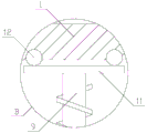
As shown in fig. 1, a floating ball control device with high mixing degree of liquid medicine for copper ore mining comprises a main body 1, a discharge pipe 2, a control valve 3 and at least two feeding devices, wherein the main body 1 is cuboid, the discharge pipe 2 is communicated with the bottom of the main body 1, the discharge pipe 2 is perpendicular to the plane where the bottom of the main body 1 is located, the control valve 3 is arranged on the discharge pipe 2, the feeding devices are uniformly arranged at the top of the main body 1, the feeding devices comprise a high-pressure tank 4, a feeding pipe 5 and a floating ball valve 6, the high-pressure tank 4 is arranged at the top of the main body 1, the bottom of the high-pressure tank 4 is communicated with the main body 1 through the feeding pipe 5, the feeding pipe 5 is parallel to the discharge pipe 2, the floating ball valve 6 is located in the main body 1, the floating ball valve 6 is arranged on the feeding pipe 5;
the liquid medicine is put into the corresponding high pressure tank 4, the air pressure in the high pressure tank 4 is adjusted according to the mixing proportion of the liquid medicine, the liquid medicine in the high pressure tank 4 enters the main body 1 through the feeding pipe 5, the flow of the liquid medicine entering the main body 1 can be adjusted according to the proportion of the air pressure through the air pressure, when the liquid medicine in the main body 1 reaches a certain liquid level, the feed pipe 5 is in a closed state through the ball float valve 6, when the material needs to be discharged, the control valve 3 is opened to discharge the material, when the liquid level of the liquid medicine in the main body 1 is reduced to a certain height, the feed pipe 5 is opened again through the ball float 6 until the liquid level of the liquid medicine in the main body 1 reaches the corresponding height, the function of mixing the liquid medicine according to a certain proportion is achieved, here, the stirring mechanism is provided to prevent the chemical liquid in the main body 1 from being insufficiently mixed due to a difference in fluidity or the like, and the chemical liquid discharged from the discharge pipe 2 from being deviated from the set ratio.
As shown in fig. 2, the rabbling mechanism includes paddle 7, transmission shaft 8, hob 9, supporting component and two stirring rods 10, transmission shaft 8 and hob 9 all with the coaxial setting of discharging pipe 2, the one end at transmission shaft 8 is installed to paddle 7, hob 9 is fixed at the other end of transmission shaft 8, paddle 7 sets up in discharging pipe 2, the axis of stirring rod 10 is perpendicular and crossing with the axis of transmission shaft 8, transmission shaft 8 is located between two stirring rods 10, stirring rod 10 is located between hob 9 and paddle 7, stirring rod 10 and transmission shaft 8 fixed connection, stirring rod 10 sets up between ball-cock assembly 6 and discharging pipe 2, supporting component sets up the one end of keeping away from transmission shaft 8 at hob 9.
Discharging pipe 2 is arranging the material in-process, makes paddle 7 drive transmission shaft 8 and hob 9 rotate under supporting component's supporting role through the flow of liquid medicine to drive stirring rod 10 and rotate, realize the effect of stirring the liquid medicine, make liquid medicine move towards keeping away from discharging pipe 2 directions through the rotation of hob 9, thereby realize the cross-flow, promote stirring effect.
As shown in fig. 3, the supporting component includes a rotating disk 11 and at least three connecting balls 12, the rotating disk 11 is installed on the screw rod 9, the connecting balls 12 are uniformly fixed on one side of the rotating disk 11 far away from the rotating shaft by taking the axis of the screw rod 9 as the central circumference, the top in the main body 1 is provided with an annular groove, the connecting balls 12 are connected with the annular groove in a sliding manner, the center of the connecting balls 12 is arranged in the annular groove, and the diameter of the connecting balls 12 is greater than the width of the notch of the annular groove.
Because of the ball diameter of connecting ball 12 is greater than the notch width of ring channel to make the ring channel can support and connect ball 12 and slide in the ring channel, the rotation of hob 9 makes through rolling disc 11 and connects ball 12 and rotate around the axis of hob 9 in the ring channel, has realized supporting hob 9 and the 8 pivoted functions of transmission shaft.
Preferably, in order to reduce the frictional force between the connection ball 12 and the annular groove, the inner wall of the annular groove is coated with grease.
The function of the grease is to reduce the friction between the connecting ball 12 and the annular groove, and to improve the smoothness of the sliding of the connecting ball 12.
As shown in fig. 4, be equipped with two at least auxiliary assembly in the main part 1, auxiliary assembly and inlet pipe 5 one-to-one, auxiliary assembly sets up the one end that is close to discharging pipe 2 at inlet pipe 5, auxiliary assembly includes supplementary piece 13 and two connecting rods 14, connecting rod 14 is parallel with inlet pipe 5, the axis of inlet pipe 5 is located between two connecting rods 14, the one end and the inlet pipe 5 fixed connection of connecting rod 14, supplementary piece 13 is fixed at the other end of connecting rod 14, the shape of supplementary piece 13 is the circular cone, supplementary piece 13 and the coaxial setting of inlet pipe 5, the maximum diameter of supplementary piece 13 is greater than the internal diameter of inlet pipe 5, one side of the maximum diameter of supplementary piece 13 sets up towards being close to discharging pipe 2 direction, be equipped with the clearance between inlet pipe 5 and the supplementary piece 13.
When liquid medicine in the high-pressure tank 4 enters the main body 1 from the feeding pipe 5, the liquid medicine generates impact force on the auxiliary block 13, the liquid medicine can be sprayed in the main body 1 in an umbrella shape through the conical shape of the auxiliary block 13, and the uniformity of liquid medicine mixing is further improved.
Preferably, in order to reduce the stress on the stirring rods 10, a support ring 15 is arranged in the main body 1, the support ring 15 is arranged coaxially with the discharge pipe 2, the support ring 15 is located between the stirring rods 10 and the discharge pipe 2, the outer diameter of the support ring 15 is greater than the maximum distance between the two stirring rods 10, the inner diameter of the support ring 15 is smaller than the maximum distance between the two stirring rods 10, the stirring rods 10 abut against support blocks, the support blocks are fixedly connected with the inner wall of the main body 1, and a gap is formed between the support ring 15 and the bottom in the main body 1.
The supporting ring 15 supports the stirring rod 10, so that the shearing force of the stirring rod 10 due to the self gravity can be reduced.
Preferably, in order to prolong the service life of the main body 1, the main body 1 is made of transparent tempered glass.
The transparent tempered glass has good corrosion resistance, can prolong the service life of the main body 1, and is convenient for a user to observe the liquid medicine in the main body 1.
In the discharging process of the device, the annular groove can support the connecting ball 12 because the ball diameter of the connecting ball 12 is larger than the width of the notch of the annular groove, the blade 7 drives the transmission shaft 8 and the spiral rod 9 to rotate by the flowing of the liquid medicine in the discharging pipe 2, so that the stirring rod 10 is driven to rotate, the effect of stirring the liquid medicine is realized, the liquid medicine moves towards the direction away from the discharging pipe 2 by the rotation of the spiral rod 9, so that cross flow is realized, and when the liquid medicine in the high-pressure tank 4 enters the main body 1 through the feeding pipe 5, the liquid medicine can be sprayed in the main body 1 in an umbrella shape through the conical shape of the auxiliary block 13;
here, the stirring rod 10 stirs the liquid medicine in the main body 1 and the screw rod 9 makes the liquid medicine generate cross flow, thereby improving the mixing uniformity of the liquid medicine in the main body 1 and reducing the deviation of the liquid medicine discharged from the discharge pipe 2 and the set proportion.
Compared with the prior art, this a floater controlling means that liquid medicine mixability is high for copper mine exploitation has improved the degree of consistency that the liquid medicine mixes in the main part 1 through rabbling mechanism, has reduced the liquid medicine of following discharging pipe 2 exhaust and has produced the deviation with the proportion of settlement, compares with current rabbling mechanism, and this rabbling mechanism need not electric drive, environmental protection and energy saving more.
In light of the foregoing, it will be apparent to those skilled in the art from this disclosure that various changes and modifications can be made without departing from the spirit and scope of the invention. The technical scope of the present invention is not limited to the content of the specification, and must be determined according to the scope of the claims.
Claims (6)
1. The utility model provides a floater controlling means that liquid medicine mixability is high for copper mine exploitation, includes main part (1), discharging pipe (2), control valve (3) and two at least feed arrangement, the shape of main part (1) is the cuboid, discharging pipe (2) and the bottom intercommunication of main part (1), discharging pipe (2) are perpendicular with the plane at main part (1) bottom place, control valve (3) set up on discharging pipe (2), feed arrangement evenly sets up the top at main part (1), feed arrangement includes high-pressure case (4), inlet pipe (5) and ball-cock assembly (6), high-pressure case (4) set up the top at main part (1), inlet pipe (5) and main part (1) intercommunication are passed through to the bottom of high-pressure case (4), inlet pipe (5) are parallel with discharging pipe (2), ball-cock assembly (6) are located main part (1), the ball float valve (6) is arranged on the feeding pipe (5), and is characterized in that a stirring mechanism is arranged in the main body (1);
the stirring mechanism comprises a blade (7), a transmission shaft (8), a screw rod (9), a support component and two stirring rods (10), the transmission shaft (8) and the screw rod (9) are both arranged coaxially with the discharge pipe (2), the paddle (7) is arranged at one end of the transmission shaft (8), the screw rod (9) is fixed at the other end of the transmission shaft (8), the paddle (7) is arranged in the discharge pipe (2), the axis of the stirring rod (10) is vertical to and intersected with the axis of the transmission shaft (8), the transmission shaft (8) is positioned between two stirring rods (10), the stirring rods (10) are positioned between the screw rod (9) and the paddle (7), the stirring rod (10) is fixedly connected with the transmission shaft (8), the stirring rod (10) is arranged between the ball float valve (6) and the discharge pipe (2), the supporting component is arranged at one end of the screw rod (9) far away from the transmission shaft (8).
2. The floating ball control device with high liquid medicine mixing degree for copper ore mining according to claim 1, characterized in that the support component comprises a rotating disc (11) and at least three connecting balls (12), the rotating disc (11) is installed on the screw rod (9), the connecting balls (12) are circumferentially and uniformly fixed on one side of the rotating disc (11) far away from the rotating shaft by taking the axis of the screw rod (9) as the center, an annular groove is formed in the top of the inside of the main body (1), the connecting balls (12) are in sliding connection with the annular groove, the center of the connecting balls (12) is arranged in the annular groove, and the diameter of the connecting balls (12) is larger than the width of the opening of the annular groove.
3. The floating ball control device with high mixing degree of liquid medicine for copper ore mining according to claim 2, characterized in that the inner wall of the annular groove is coated with lubricating grease.
4. The floating ball control device with high mixing degree of liquid medicine for copper ore mining according to claim 1, characterized in that at least two auxiliary assemblies are arranged in the main body (1), the auxiliary assemblies correspond to the feeding pipe (5) one by one, the auxiliary assemblies are arranged at one end of the feeding pipe (5) close to the discharging pipe (2), the auxiliary assemblies comprise an auxiliary block (13) and two connecting rods (14), the connecting rods (14) are parallel to the feeding pipe (5), the axis of the feeding pipe (5) is positioned between the two connecting rods (14), one end of each connecting rod (14) is fixedly connected with the feeding pipe (5), the auxiliary block (13) is fixed at the other end of each connecting rod (14), the auxiliary block (13) is conical in shape, the auxiliary block (13) is coaxially arranged with the feeding pipe (5), and the maximum diameter of the auxiliary block (13) is larger than the inner diameter of the feeding pipe (5), one side of the maximum diameter of the auxiliary block (13) is arranged towards the direction close to the discharge pipe (2), and a gap is formed between the feed pipe (5) and the auxiliary block (13).
5. The floating ball control device with high liquid medicine mixing degree for copper ore mining according to claim 1, characterized in that a support ring (15) is arranged in the main body (1), the support ring (15) is coaxially arranged with the discharge pipe (2), the support ring (15) is positioned between the stirring rods (10) and the discharge pipe (2), the outer diameter of the support ring (15) is larger than the maximum distance between the two stirring rods (10), the inner diameter of the support ring (15) is smaller than the maximum distance between the two stirring rods (10), the stirring rods (10) are abutted against a support block, the support block is fixedly connected with the inner wall of the main body (1), and a gap is arranged between the support ring (15) and the inner bottom of the main body (1).
6. The floating ball control device with high mixing degree of liquid medicine for copper ore mining according to claim 1, characterized in that the main body (1) is made of transparent toughened glass.
Priority Applications (1)
| Application Number | Priority Date | Filing Date | Title |
|---|---|---|---|
| CN201920403066.3U CN210021832U (en) | 2019-03-27 | 2019-03-27 | Floating ball control device with high liquid medicine mixing degree for copper ore mining |
Applications Claiming Priority (1)
| Application Number | Priority Date | Filing Date | Title |
|---|---|---|---|
| CN201920403066.3U CN210021832U (en) | 2019-03-27 | 2019-03-27 | Floating ball control device with high liquid medicine mixing degree for copper ore mining |
Publications (1)
| Publication Number | Publication Date |
|---|---|
| CN210021832U true CN210021832U (en) | 2020-02-07 |
Family
ID=69356642
Family Applications (1)
| Application Number | Title | Priority Date | Filing Date |
|---|---|---|---|
| CN201920403066.3U Active CN210021832U (en) | 2019-03-27 | 2019-03-27 | Floating ball control device with high liquid medicine mixing degree for copper ore mining |
Country Status (1)
| Country | Link |
|---|---|
| CN (1) | CN210021832U (en) |
Cited By (4)
| Publication number | Priority date | Publication date | Assignee | Title |
|---|---|---|---|---|
| CN111790282A (en) * | 2020-06-24 | 2020-10-20 | 阜阳天祥食品科技有限公司 | Sesame blend oil modulation equipment |
| CN111992063A (en) * | 2020-09-08 | 2020-11-27 | 浙江兰电环保集团有限公司 | Lime milk preparation equipment for desulfurization and denitrification |
| CN112827663A (en) * | 2020-12-31 | 2021-05-25 | 新巴尔虎右旗荣达矿业有限责任公司 | Flotation cell liquid level regulating device |
| CN113578199A (en) * | 2021-08-02 | 2021-11-02 | 东北大学 | Corrosion-resistant reaction kettle in high-temperature and high-pressure strong acid medium environment |
-
2019
- 2019-03-27 CN CN201920403066.3U patent/CN210021832U/en active Active
Cited By (5)
| Publication number | Priority date | Publication date | Assignee | Title |
|---|---|---|---|---|
| CN111790282A (en) * | 2020-06-24 | 2020-10-20 | 阜阳天祥食品科技有限公司 | Sesame blend oil modulation equipment |
| CN111992063A (en) * | 2020-09-08 | 2020-11-27 | 浙江兰电环保集团有限公司 | Lime milk preparation equipment for desulfurization and denitrification |
| CN111992063B (en) * | 2020-09-08 | 2022-10-25 | 河北大成新材料有限公司 | Lime milk preparation equipment for desulfurization and denitrification |
| CN112827663A (en) * | 2020-12-31 | 2021-05-25 | 新巴尔虎右旗荣达矿业有限责任公司 | Flotation cell liquid level regulating device |
| CN113578199A (en) * | 2021-08-02 | 2021-11-02 | 东北大学 | Corrosion-resistant reaction kettle in high-temperature and high-pressure strong acid medium environment |
Similar Documents
| Publication | Publication Date | Title |
|---|---|---|
| CN210021832U (en) | Floating ball control device with high liquid medicine mixing degree for copper ore mining | |
| CN207187594U (en) | A kind of homogenizer | |
| CN103341336B (en) | The agitator of stirred tank | |
| CN1278894A (en) | An Improved flow axially-rotated, split venturi valve | |
| CN103306647A (en) | Active rotary dynamic mixer applicable to thick oil mixed with thin oil mining | |
| CN106050728B (en) | A kind of inner wall imitates the seal cavity of cyclone spiral grooves composite construction | |
| CN112121471B (en) | Method and system for determining optimal thickening mode of differential full tailings | |
| CN107377236B (en) | Turbulent flow dosing device for mineral separation equipment | |
| CN204197705U (en) | A kind of aluminum paste feedway | |
| CN107388040B (en) | Ore pulp conveying device for mineral separation equipment | |
| CN207230166U (en) | The pulp conveying device on preparation equipment | |
| CN111442096B (en) | Valve core self-rotating passive prevention and control type solid-containing multiphase flow control valve | |
| CN108854713A (en) | A kind of feeding system convenient for desulfurization of gypsum | |
| CN100369657C (en) | Horizontal inclined rotary fluidized bed desulfurizing reactor | |
| CN206951022U (en) | A kind of Powerless spiral fluid is well mixed device | |
| CN201030294Y (en) | Rubber shred-asphalt mixture agitating jug | |
| CN204385225U (en) | A kind of desulfur agitator | |
| CN205379572U (en) | Assembled fire gun | |
| CN220482133U (en) | Concrete discharge hopper | |
| CN208456140U (en) | A kind of inner tube rotary type concrete delivery pipe | |
| CN209752710U (en) | Ore pulp stirring tank | |
| CN207324646U (en) | A kind of fire-proof sealing material mixer | |
| CN205225310U (en) | Pipeline with air outlet | |
| CN111121203A (en) | Ice-water mixer and cooling method of regional cooling system | |
| CN206064216U (en) | A kind of industrial chemicals mixing arm |
Legal Events
| Date | Code | Title | Description |
|---|---|---|---|
| GR01 | Patent grant |