CN209983017U - Heat radiator for electromechanical device - Google Patents
Heat radiator for electromechanical device Download PDFInfo
- Publication number
- CN209983017U CN209983017U CN201920825487.5U CN201920825487U CN209983017U CN 209983017 U CN209983017 U CN 209983017U CN 201920825487 U CN201920825487 U CN 201920825487U CN 209983017 U CN209983017 U CN 209983017U
- Authority
- CN
- China
- Prior art keywords
- electromechanical
- fan
- shell
- fixing plate
- plate
- Prior art date
- Legal status (The legal status is an assumption and is not a legal conclusion. Google has not performed a legal analysis and makes no representation as to the accuracy of the status listed.)
- Expired - Fee Related
Links
Images


Abstract
The utility model relates to a heat dissipation device of electromechanical equipment, which comprises an electromechanical shell, wherein a first fan frame is arranged at the top of the electromechanical shell, a first fixing plate is arranged at the outer side of the first fan frame, the first fixing plate is fixedly connected with the electromechanical shell, a first fan is arranged in the first fan frame, a first mounting frame is fixedly connected with the top of the first fixing plate, a first mounting groove and a first square hole are arranged in the first mounting frame, the first mounting groove is communicated with the first square hole, a first dust screen is arranged in the first mounting groove, the structure is simple, the design is reasonable, heat of the electromechanical equipment in the electromechanical shell is better absorbed through a heat conducting plate, the heat led out by a heat dissipation fin is dissipated by a second fan, the heat dissipation effect is enhanced through the first fan, and the damping and buffering are carried out on the electromechanical shell, the influence of the vibration of the first fan and the second fan on the equipment is reduced, and a certain dustproof effect is achieved.
Description
Technical Field
The utility model relates to a heat abstractor of electromechanical device belongs to heat abstractor technical field.
Background
With the development of innovation and opening, China has entered into the industrialized era, electromechanical equipment is necessary in the manufacturing industry, electromechanical equipment can produce a large amount of heat energy in the processing and production process, if the heat energy can not be conducted out in time, equipment damage is easily caused, the heat energy generated by the equipment can be better led out, the led-out heat energy is discharged, the heat dissipation effect on the equipment is enhanced through a heat dissipation hole, when the fan is used for heat dissipation, the rotating fan can vibrate, the influence on the equipment is caused, a certain buffering and damping effect needs to be achieved, a certain dustproof effect needs to be achieved, the influence of dust on the equipment is reduced, and therefore further improvement is needed.
SUMMERY OF THE UTILITY MODEL
The utility model aims to provide a heat dissipation device of electromechanical equipment, through being provided with a heat conduction plate, the heat generated by the equipment can be absorbed, and the absorbed heat can be dissipated into a second fan frame through a heat dissipation fin, through being provided with a second fan, the heat on the heat dissipation fin can be discharged out of the electromechanical shell, through being provided with a second fixing plate and a supporting block, the second fan frame can be fixed, so that the second fan frame is more stable, through being provided with a first heat dissipation hole and the first fan, the heat dissipation effect on the equipment in the electromechanical shell can be further enhanced, and through being provided with a second heat dissipation hole, the air circulation effect in the electromechanical shell can be improved, through being provided with the first fixing plate, the first fan frame can be better fixed, through being provided with a first mounting rack and a second mounting rack, the first mounting groove and the second mounting groove are formed, the first dust screen and the second dust screen can be conveniently arranged, the first fixing plate and the first fan frame can be conveniently fixed by arranging the first bolt, the second fixing plate and the second fan frame can be conveniently fixed by arranging the second bolt, the support piece is arranged and is connected with the electromechanical shell through the third bolt, the second fixing plate can be supported, meanwhile, the arrangement of the protection plate is convenient, the electromechanical shell can be buffered and damped by arranging the spring, the limiting circular plate, the buffer rod and the buffer sleeve, a certain reduction effect can be achieved on vibration generated by rotation of the first fan and the second fan, so that the influence on equipment is reduced, the protection plate can be arranged to protect the space between the bottom plate and the electromechanical shell, through being provided with support column, base and slipmat, make placing more stable of device, through being provided with first dust screen, second dust screen and third dust screen, can prevent that the dust from getting into in the electromechanical shell to reduce the influence of dust to equipment, prolong the life of equipment, in order to solve the problem of proposing among the above-mentioned background art.
In order to achieve the above object, the utility model provides a following technical scheme:
a heat dissipation device of electromechanical equipment comprises an electromechanical shell, wherein a first fan frame is arranged at the top of the electromechanical shell, a first fixing plate is arranged on the outer side of the first fan frame and fixedly connected with the electromechanical shell, a first fan is arranged in the first fan frame, a first mounting frame is fixedly connected with the top of the first fixing plate, a first mounting groove and a first square hole are formed in the first mounting frame, the first mounting groove is communicated with the first square hole, a first dust screen is arranged in the first mounting groove, second fan frames are symmetrically arranged on two sides of the electromechanical shell, a second fan is arranged in the second fan frame, a second fixing plate is arranged on the outer side of the second fan frame and fixedly connected with the electromechanical shell, and a second mounting frame is fixedly connected to one side of the second fixing plate, set up second mounting groove and second quad slit in the second mounting bracket, be provided with the second dust screen in the second mounting groove, the radiating groove corresponding with second fan frame is seted up to electromechanical housing both sides, be provided with radiating fin in the radiating groove, just radiating fin one side is connected with the heat-conducting plate, the heat-conducting plate sets up inside electromechanical housing, electromechanical housing below is provided with the bottom plate, bottom plate top fixedly connected with buffer sleeve, the buffer beam that is provided with in the buffer sleeve, buffer beam top and electromechanical housing fixed connection, the buffer beam bottom is provided with the restriction plectane, just fixedly connected with spring between restriction plectane bottom and the buffer sleeve.
Furthermore, the top of the electromechanical shell is provided with a first heat dissipation hole corresponding to the first fan.
Furthermore, a third dust screen is arranged at the bottom of the electromechanical shell, and a second heat dissipation hole corresponding to the third dust screen is formed in the bottom of the electromechanical shell.
Furthermore, a supporting block is arranged in the second fixing plate, and the supporting block is attached to the second fan frame.
Furthermore, first bolts are arranged on the periphery of the first fixing plate, and bolt tails of the first bolts penetrate through the first fixing plate and are in threaded connection with the first fan frame.
Furthermore, second bolts are arranged on the periphery of the second fixing plate, and bolt tails of the second bolts penetrate through the second fixing plate and are in threaded connection with the second fan frame.
Furthermore, the bottom plate bottom is provided with the support column, just the support column bottom is provided with the base, the base bottom is provided with the slipmat.
Furthermore, support pieces are arranged on two sides of the electromechanical shell, the tops of the support pieces are attached to the second fixing plate, a third bolt is arranged on one side of each support piece, and the bolt tail of each third bolt penetrates through the support pieces and is in threaded connection with the electromechanical shell.
Furthermore, the bottom of the supporting piece is provided with a protection plate, and the protection plate is arranged around the bottom plate.
The utility model has the advantages that: the utility model relates to a heat dissipation device of electromechanical equipment, through being provided with the heat-conducting plate, can absorb the heat that equipment produced, and distribute the absorbed heat into the second fan frame through the radiating fin, through being provided with the second fan, can discharge the heat on the radiating fin outside the electromechanical shell, through being provided with second fixed plate and supporting shoe, can fix the second fan frame, make the second fan frame more stable, through being provided with first louvre and first fan, can further strengthen the radiating effect to the equipment in the electromechanical shell, and through being provided with the second louvre, can improve the effect of circulation of air in the electromechanical shell, through being provided with the first fixed plate, can better fix the first fan frame, through being provided with first mounting bracket and second mounting bracket, and set up first mounting groove and second mounting groove, the first dust screen and the second dust screen can be more conveniently arranged, the first bolt is arranged, the first fixing plate and the first fan frame are conveniently fixed, the second bolt is arranged, the second fixing plate and the second fan frame are conveniently fixed, the supporting piece is arranged, the supporting piece and the electromechanical shell are connected through the third bolt, the second fixing plate can be supported, meanwhile, the arrangement of a protection plate is convenient, the spring, the limiting circular plate, the buffer rod and the buffer sleeve are arranged, the electromechanical shell can be buffered and damped, vibration generated by rotation of the first fan and the second fan can be reduced to a certain degree, influences on equipment are reduced, the protection plate can protect the space between the base plate and the electromechanical shell, the supporting column and the electromechanical shell are arranged, and the first bolt and the second bolt are arranged, Base and slipmat make placing more stable of device, through being provided with first dust screen, second dust screen and third dust screen, can prevent that the dust from getting into in the electromechanical casing to reduce the influence of dust to equipment, prolong the life of equipment, the practicality is strong, suitable extensively implementation.
Drawings
The accompanying drawings are included to provide a further understanding of the invention, and are incorporated in and constitute a part of this specification, illustrate embodiments of the invention, and together with the description serve to explain the invention and not to limit the invention.
Fig. 1 is a schematic view of the overall structure of a heat dissipation device for an electromechanical device according to the present invention;
fig. 2 is a schematic view of an internal structure of a heat dissipation device of an electromechanical device according to the present invention;
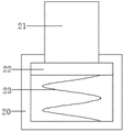
fig. 3 is a schematic view of an internal structure of a buffer sleeve of a heat dissipation device of an electromechanical device according to the present invention;
fig. 4 is a schematic view of a first mounting bracket of a heat dissipation device of an electromechanical device according to the present invention;
reference numbers in the figures: 1. an electromechanical housing; 2. a first fan frame; 3. a first fixing plate; 4. a first fan; 5. a first mounting bracket; 6. a first mounting groove; 7. a first square hole; 8. a first dust screen; 9. a second fan frame; 10. a second fan; 11. a second fixing plate; 12. a second mounting bracket; 13. a second mounting groove; 14. a second square hole; 15. a second dust screen; 16. a heat sink; 17. a heat dissipating fin; 18. a heat conducting plate; 19. a base plate; 20. a buffer sleeve; 21. a buffer rod; 22. a restraining disk; 23. a spring; 24. a first heat dissipation hole; 25. a third dust prevention net; 26. a second heat dissipation hole; 27. a support block; 28. a first bolt; 29. a second bolt; 30. a support pillar; 31. a base; 32. a support member; 33. a third bolt; 34. and (4) a protective plate.
Detailed Description
The preferred embodiments of the present invention will be described in conjunction with the accompanying drawings, and it will be understood that they are presented herein only to illustrate and explain the present invention, and not to limit the present invention.
Referring to fig. 1-4, the present invention provides a technical solution: a heat dissipation device of electromechanical equipment comprises an electromechanical shell 1, wherein a first fan frame 2 is arranged at the top of the electromechanical shell 1, a first fixing plate 3 is arranged on the outer side of the first fan frame 2, the first fixing plate 3 is fixedly connected with the electromechanical shell 1, a first fan 4 is arranged in the first fan frame 2, the heat dissipation effect on the equipment in the electromechanical shell 1 is further enhanced, a first mounting frame 5 is fixedly connected with the top of the first fixing plate 3, a first mounting groove 6 and a first square hole 7 are formed in the first mounting frame 5, the first fan frame 2 cannot influence the first dust screen 8 when the first dust screen 8 is conveniently arranged, the first mounting groove 6 is communicated with the first square hole 7, a first dust screen 8 is arranged in the first mounting groove 6, and second fan frames 9 are symmetrically arranged on two sides of the electromechanical shell 1, a second fan 10 is arranged in the second fan frame 9, heat on the radiating fins 17 is discharged out of the electromechanical shell 1, a second fixing plate 11 is arranged on the outer side of the second fan frame 9, the second fixing plate 11 is fixedly connected with the electromechanical shell 1, a second mounting frame 12 is fixedly connected to one side of the second fixing plate 11, a second mounting groove 13 and a second square hole 14 are formed in the second mounting frame 12, the second dust screen 15 is conveniently arranged, the second fan frame 9 cannot influence the second dust screen 15, a second dust screen 15 is arranged in the second mounting groove 13, radiating grooves 16 corresponding to the second fan frame 9 are formed in two sides of the electromechanical shell 1, the radiating fins 17 are arranged in the radiating grooves 16, a heat conducting plate 18 is connected to one side of each radiating fin 17, and heat generated by equipment is absorbed, and with the absorbed heat through radiating fin 17 give off to in the second fan frame 9, heat-conducting plate 18 sets up inside electromechanical casing 1, electromechanical casing 1 below is provided with bottom plate 19, 19 top fixedly connected with buffer tube 20 of bottom plate, be provided with buffer beam 21 in the buffer tube 20, buffer beam 21 top and electromechanical casing 1 fixed connection, buffer beam 21 bottom is provided with restriction plectane 22, just fixedly connected with spring 23 between restriction plectane 22 bottom and the buffer tube 20 cushions shock attenuation to electromechanical casing 1, to the vibrations of first fan 4 and the rotation of second fan 10 production, can play certain reduction effect to the reduction causes the influence to equipment.
More specifically, the top of the electromechanical housing 1 is provided with a first heat dissipation hole 24 corresponding to the first fan 4, so as to further enhance the heat dissipation effect on the devices in the electromechanical housing 1, the bottom of the electromechanical housing 1 is provided with a third dust screen 25, and the bottom of the electromechanical housing 1 is provided with a second heat dissipation hole 26 corresponding to the third dust screen 25, so as to enhance the air circulation effect in the electromechanical housing 1, the second fixing plate 11 is provided with a supporting block 27, and the supporting block 27 is attached to the second fan frame 9, so as to fix the second fan frame 9, so as to make the second fan frame 9 more stable, the periphery of the first fixing plate 3 is provided with a first bolt 28, the bolt tail of the first bolt 28 penetrates through the first fixing plate 3 to be in threaded connection with the first fan frame 2, so as to facilitate the fixing between the first fixing plate 3 and the first fan frame 2, the periphery of the second fixing plate 11 is provided with second bolts 29, the bolt tails of the second bolts 29 penetrate through the second fixing plate 11 and are in threaded connection with the second fan frame 9, the second fixing plate 11 and the second fan frame 9 are conveniently fixed, the bottom of the bottom plate 19 is provided with a support column 30, the bottom of the support column 30 is provided with a base 31, the bottom of the base 31 is provided with an anti-slip pad, so that the device is more stably placed, the two sides of the electromechanical shell 1 are provided with support pieces 32, the support of the second fixing plate 11 is facilitated, meanwhile, the arrangement of the protection plates 34 is facilitated, the top of each support piece 32 is attached to the second fixing plate 11, one side of each support piece 32 is provided with a third bolt 33, the bolt tails of the third bolts 33 penetrate through the support pieces 32 and are in threaded connection with the electromechanical shell 1, the support pieces 32 are connected with the electromechanical shell 1, and the protection, and the protection plate 34 is arranged around the bottom plate 19 to protect between the bottom plate 19 and the electromechanical housing 1.
The utility model discloses the theory of operation: when the equipment in the electromechanical shell 1 operates, a part of heat generated by the equipment is absorbed by the heat conducting plate 18 and is converted and radiated into the second fan frame 9 through the heat radiating fins 17, the heat is discharged by the second fan 10, and some heat is discharged out of the electromechanical shell 1 through the first fan 4 and the first heat radiating holes 24, the arrangement of the second heat radiating holes 26 improves the air fluidity in the electromechanical shell 1, certain vibration can be generated when the first fan 4 and the second fan 10 rotate, the damping and shock absorption can be performed through the spring 23, the limiting circular plate 22, the damping rod 21 and the damping sleeve 20, so that the influence on the equipment is reduced, the arrangement of the first dust screen 8, the second dust screen 15 and the third dust screen 25 can prevent dust from entering the electromechanical shell 1, so that the influence of the dust on the equipment is reduced, and the service life of the equipment is prolonged, simple structure, the practicality is strong.
The above is the preferred embodiment of the present invention, and the technical personnel in the field of the present invention can also change and modify the above embodiment, therefore, the present invention is not limited to the above specific embodiment, and any obvious improvement, replacement or modification made by the technical personnel in the field on the basis of the present invention all belong to the protection scope of the present invention.
Claims (9)
1. A heat dissipation device for an electromechanical apparatus, comprising an electromechanical housing (1), characterized in that: the electromechanical shell (1) is provided with a first fan frame (2) at the top, a first fixing plate (3) is arranged on the outer side of the first fan frame (2), the first fixing plate (3) is fixedly connected with the electromechanical shell (1), a first fan (4) is arranged in the first fan frame (2), a first mounting frame (5) is fixedly connected with the top of the first fixing plate (3), a first mounting groove (6) and a first square hole (7) are formed in the first mounting frame (5), the first mounting groove (6) is communicated with the first square hole (7), a first dust screen (8) is arranged in the first mounting groove (6), second fan frames (9) are symmetrically arranged on two sides of the electromechanical shell (1), a second fan (10) is arranged in the second fan frames (9), and a second fixing plate (11) is arranged on the outer side of the second fan frames (9), the second fixing plate (11) is fixedly connected with the electromechanical shell (1), a second mounting frame (12) is fixedly connected to one side of the second fixing plate (11), a second mounting groove (13) and a second square hole (14) are formed in the second mounting frame (12), a second dust screen (15) is arranged in the second mounting groove (13), radiating grooves (16) corresponding to the second fan frame (9) are formed in two sides of the electromechanical shell (1), radiating fins (17) are arranged in the radiating grooves (16), a heat conducting plate (18) is connected to one side of each radiating fin (17), the heat conducting plate (18) is arranged inside the electromechanical shell (1), a bottom plate (19) is arranged below the electromechanical shell (1), a buffer sleeve (20) is fixedly connected to the top of the bottom plate (19), and a buffer rod (21) is arranged in the buffer sleeve (20), the top of the buffer rod (21) is fixedly connected with the electromechanical shell (1), a limiting circular plate (22) is arranged at the bottom of the buffer rod (21), and a spring (23) is fixedly connected between the bottom of the limiting circular plate (22) and the buffer sleeve (20).
2. The heat dissipating apparatus for an electromechanical device according to claim 1, wherein: the top of the electromechanical shell (1) is provided with a first heat dissipation hole (24) corresponding to the first fan (4).
3. The heat dissipating apparatus for an electromechanical device according to claim 1, wherein: the electromechanical shell (1) is provided with a third dust prevention net (25) at the bottom, and a second heat dissipation hole (26) corresponding to the third dust prevention net (25) is formed in the electromechanical shell (1) at the bottom.
4. The heat dissipating apparatus for an electromechanical device according to claim 1, wherein: a supporting block (27) is arranged in the second fixing plate (11), and the supporting block (27) is attached to the second fan frame (9).
5. The heat dissipating apparatus for an electromechanical device according to claim 1, wherein: first bolt (28) are arranged around first fixed plate (3), and first bolt (28) bolt tail runs through first fixed plate (3) and is connected with first fan frame (2) threaded connection.
6. The heat dissipating apparatus for an electromechanical device according to claim 1, wherein: and second bolts (29) are arranged on the periphery of the second fixing plate (11), and bolt tails of the second bolts (29) penetrate through the second fixing plate (11) and are in threaded connection with the second fan frame (9).
7. The heat dissipating apparatus for an electromechanical device according to claim 1, wherein: the anti-skid floor is characterized in that a supporting column (30) is arranged at the bottom of the bottom plate (19), a base (31) is arranged at the bottom of the supporting column (30), and an anti-skid pad is arranged at the bottom of the base (31).
8. The heat dissipating apparatus for an electromechanical device according to claim 1, wherein: support piece (32) are arranged on two sides of electromechanical shell (1), the top of support piece (32) is attached to second fixing plate (11), third bolt (33) is arranged on one side of support piece (32), and bolt tail of third bolt (33) penetrates through support piece (32) and electromechanical shell (1) and is in threaded connection.
9. The heat dissipating apparatus for an electromechanical device according to claim 8, wherein: the bottom of the supporting piece (32) is provided with a protection plate (34), and the protection plate (34) is arranged on the periphery of the bottom plate (19).
Priority Applications (1)
| Application Number | Priority Date | Filing Date | Title |
|---|---|---|---|
| CN201920825487.5U CN209983017U (en) | 2019-06-03 | 2019-06-03 | Heat radiator for electromechanical device |
Applications Claiming Priority (1)
| Application Number | Priority Date | Filing Date | Title |
|---|---|---|---|
| CN201920825487.5U CN209983017U (en) | 2019-06-03 | 2019-06-03 | Heat radiator for electromechanical device |
Publications (1)
| Publication Number | Publication Date |
|---|---|
| CN209983017U true CN209983017U (en) | 2020-01-21 |
Family
ID=69265252
Family Applications (1)
| Application Number | Title | Priority Date | Filing Date |
|---|---|---|---|
| CN201920825487.5U Expired - Fee Related CN209983017U (en) | 2019-06-03 | 2019-06-03 | Heat radiator for electromechanical device |
Country Status (1)
| Country | Link |
|---|---|
| CN (1) | CN209983017U (en) |
Cited By (1)
| Publication number | Priority date | Publication date | Assignee | Title |
|---|---|---|---|---|
| CN111597595A (en) * | 2020-05-25 | 2020-08-28 | 常州工程职业技术学院 | Computer protection equipment |
-
2019
- 2019-06-03 CN CN201920825487.5U patent/CN209983017U/en not_active Expired - Fee Related
Cited By (1)
| Publication number | Priority date | Publication date | Assignee | Title |
|---|---|---|---|---|
| CN111597595A (en) * | 2020-05-25 | 2020-08-28 | 常州工程职业技术学院 | Computer protection equipment |
Similar Documents
| Publication | Publication Date | Title |
|---|---|---|
| CN111649200B (en) | Multifunctional base for computer mainframe | |
| CN209880406U (en) | Capacitor with shock-absorbing function | |
| CN209983017U (en) | Heat radiator for electromechanical device | |
| CN107479676B (en) | Heat radiation structure with shock-absorbing function for computer | |
| CN210637719U (en) | Computer base device capable of radiating | |
| CN210518392U (en) | Self-radiating router | |
| JP3176477U (en) | Blower fan body cushioning structure | |
| CN214627025U (en) | Industry switch that possesses heat dissipation mechanism | |
| CN211698847U (en) | Heat dissipation device for big data server | |
| CN214790154U (en) | Damping base for computer main box | |
| CN209895280U (en) | Radiator fixing structure | |
| CN209555514U (en) | A kind of sewing machine energy-saving electric machine radiator | |
| CN110750143A (en) | Big data server with efficient heat dissipation function | |
| CN216357919U (en) | Cloud storage node application server | |
| CN216697817U (en) | Hard disk mixed structure suitable for BIM design | |
| WO2019227458A1 (en) | Shock-absorbing and buffering type motor base | |
| CN219042336U (en) | Cinema projector base cabinet heat radiation structure | |
| CN213628660U (en) | Air conditioning unit damping device with purifier | |
| CN212135322U (en) | Computer with waterproof function | |
| CN210036336U (en) | Novel vibration cooler | |
| CN211202345U (en) | Low-noise computer cooling fan | |
| CN211429581U (en) | LED driving power supply | |
| CN220323835U (en) | Shock-proof mute computer box | |
| CN219370287U (en) | Miniature server with shock absorption function | |
| CN210036395U (en) | Vibration cooler structure convenient to installation |
Legal Events
| Date | Code | Title | Description |
|---|---|---|---|
| GR01 | Patent grant | ||
| GR01 | Patent grant | ||
| CF01 | Termination of patent right due to non-payment of annual fee | ||
| CF01 | Termination of patent right due to non-payment of annual fee |
Granted publication date: 20200121 Termination date: 20200603 |