CN209977859U - But height-adjusting's LED lamp linkage - Google Patents
But height-adjusting's LED lamp linkage Download PDFInfo
- Publication number
- CN209977859U CN209977859U CN201921256644.1U CN201921256644U CN209977859U CN 209977859 U CN209977859 U CN 209977859U CN 201921256644 U CN201921256644 U CN 201921256644U CN 209977859 U CN209977859 U CN 209977859U
- Authority
- CN
- China
- Prior art keywords
- rod
- handle
- led lamp
- fixing plate
- limiting
- Prior art date
- Legal status (The legal status is an assumption and is not a legal conclusion. Google has not performed a legal analysis and makes no representation as to the accuracy of the status listed.)
- Expired - Fee Related
Links
Images


Abstract
The utility model discloses a but height-adjusting's LED lamp linkage, including base, fixed plate, baffle and lamp body, the top of base is provided with the bracing piece, and is fixed with the driving lever on the bottom outer wall of bracing piece, first spacing groove has all been seted up to the inside of driving lever and base, and the internal connection of first spacing groove has first gag lever post, the stay cord has been run through to the inside of connecting piece, and the stay cord is connected with the rotary rod through fixed pulley, the handle is installed on the right side of rotary rod, the lamp body is installed in the below of mounting panel. This but height-adjusting's LED lamp linkage, the mounting panel is connected with the fixed plate, and connecting piece on the fixed plate is connected with the stay cord to the stay cord is connected with the rotary rod through fixed pulley, and when the rotary rod rotated, can drive the stay cord and receive and unreel the operation, thereby drive fixed plate and mounting panel through the stay cord and carry out the lift migration, realize the regulation to the lamp body height.
Description
Technical Field
The utility model relates to a relevant technical field of LED lamp specifically is a but height-adjusting's LED lamp linkage.
Background
The LED lamp is a relatively common lamp in our life, and application range is very extensive moreover, and the LED lamp can have a lot of colours, and the colour that uses in different occasions also can be different, if when outdoor interim illumination, generally needs white light to hang the LED lamp and install on the support frame, convenient operation.
However, the existing LED lamp suspension device still has some disadvantages in the using process, for example, the height of the LED lamp is not convenient to adjust, and the height is usually adjusted by the support frame, so that the operation is not convenient, the practicability of the LED lamp is also reduced, and meanwhile, the irradiation angle of the LED lamp is not convenient to adjust under the condition that the support frame is not moved, so that the using efficiency of the suspension device is reduced.
SUMMERY OF THE UTILITY MODEL
An object of the utility model is to provide a but height-adjusting's LED lamp linkage to solve the linkage on the existing market that above-mentioned background art provided and be not convenient for highly adjusting the LED lamp, all lean on the support frame to adjust height usually, not only inconvenient operation has so also reduced the practicality of LED lamp, is not convenient for adjust the angle of shining of LED lamp simultaneously under the condition of unmovable support frame, thereby has reduced linkage's availability factor's problem.
In order to achieve the above object, the utility model provides a following technical scheme: a height-adjustable LED lamp suspension device comprises a base, a fixing plate, a baffle plate and a lamp body, wherein a supporting rod is arranged above the base, a driving rod is fixed on the outer wall of the bottom of the supporting rod, first limiting grooves are formed in the driving rod and the base, a first limiting rod is connected inside the first limiting groove, the fixing plate is arranged inside the supporting rod, a mounting plate is connected to the left side of the fixing plate, a connecting piece is arranged at the top of the fixing plate, a pull rope penetrates through the inside of the connecting piece and is connected with a rotating rod through a fixing pulley, a handle is arranged on the right side of the rotating rod, the baffle plate is arranged above the handle, a second limiting groove is formed in the baffle plate and the handle, a second limiting rod is connected inside the second limiting groove, clamping blocks are arranged on the front side and the rear side of the fixing plate, and the clamping blocks are connected with the, and the grooves are formed in the inner walls of the front side and the rear side of the supporting rod, and the lamp body is arranged below the mounting plate.
Preferably, the connection mode of the support rod and the base is that a rotary bearing is connected, the deflector rod on the outer wall of the support rod is distributed in an equal angle, and the connection mode of the deflector rod and the first limit groove in the base is in threaded connection with the first limit rod.
Preferably, the mounting plate and the fixing plate are connected in a welding manner, and a gap is reserved between the fixing plate and the rotating rod.
Preferably, the connection mode of handle and swiveling lever is bolted connection, and angular distribution such as the inside second spacing groove of handle to be connected for the block between handle and the inside second spacing groove of baffle and the second gag lever post.
Preferably, the fixture block and the fixing plate are of an integrated structure, the fixture block and the supporting rod form a sliding structure through the groove, the number of the fixture block is two, and meanwhile, the 2 fixture blocks are symmetrically distributed about the longitudinal center line of the fixing plate.
Compared with the prior art, the beneficial effects of the utility model are that: the height-adjustable LED lamp suspension device;
(1) the outer wall of the supporting rod is provided with a driving rod, the supporting rod and the base are connected through a rotating bearing, and the driving rod and the base are both internally provided with a first limiting groove, so that the supporting rod can be rotated without moving the whole device, the angle of the lamp body can be adjusted, the lighting direction can be changed, and meanwhile, the rotating supporting rod can be fixed through the first limiting groove, which is very convenient;
(2) the mounting plate is connected with the fixing plate, the connecting piece on the fixing plate is connected with the pull rope, the pull rope is connected with the rotating rod through the fixing pulley, and when the rotating rod rotates, the pull rope can be driven to perform winding and unwinding operations, so that the fixing plate and the mounting plate are driven to perform lifting movement through the pull rope, and the height of the lamp body is adjusted;
(3) the inside of handle and baffle all is provided with the second spacing groove, after the handle is rotatory to certain angle, is convenient for carry on spacingly through the second spacing groove to the handle, effectively prevents that self-rotation's phenomenon from appearing in the handle, and then ensures the normal use of lamp body.
Drawings
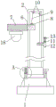
FIG. 1 is a schematic view of the overall main sectional structure of the present invention;
FIG. 2 is an enlarged schematic view of the structure at A of FIG. 1 according to the present invention;
FIG. 3 is a schematic view of the left side cut-away structure of the fixing plate and the fixture block of the present invention;
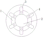
FIG. 4 is a schematic view of the connection structure of the support rod and the shift lever according to the present invention;
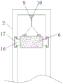
fig. 5 is a schematic view of the structure of the handle and the baffle plate of the present invention.
In the figure: 1. a base; 2. a support bar; 3. a deflector rod; 4. a first limit groove; 5. a first limit rod; 6. a fixing plate; 7. mounting a plate; 8. a connecting member; 9. pulling a rope; 10. fixing the pulley; 11. rotating the rod; 12. a handle; 13. a baffle plate; 14. a second limit groove; 15. a second limiting rod; 16. a clamping block; 17. a groove; 18. and a lamp body.
Detailed Description
The technical solutions in the embodiments of the present invention will be described clearly and completely with reference to the accompanying drawings in the embodiments of the present invention, and it is obvious that the described embodiments are only some embodiments of the present invention, not all embodiments. Based on the embodiments in the present invention, all other embodiments obtained by a person skilled in the art without creative work belong to the protection scope of the present invention.
Referring to fig. 1-5, the present invention provides a technical solution: a height-adjustable LED lamp suspension device comprises a base 1, a support rod 2, a deflector rod 3, a first limit groove 4, a first limit rod 5, a fixing plate 6, a mounting plate 7, a connecting piece 8, a pull rope 9, a fixed pulley 10, a rotary rod 11, a handle 12, a baffle plate 13, a second limit groove 14, a second limit rod 15, a fixture block 16, a groove 17 and a lamp body 18, wherein the support rod 2 is arranged above the base 1, the deflector rod 3 is fixed on the outer wall of the bottom of the support rod 2, the deflector rod 3 and the base 1 are both internally provided with the first limit groove 4, the first limit rod 5 is connected inside the first limit groove 4, the fixing plate 6 is arranged inside the support rod 2, the mounting plate 7 is connected to the left side of the fixing plate 6, the connecting piece 8 is arranged at the top of the fixing plate 6, the pull rope 9 penetrates through the connecting piece 8, and the pull rope 9 is connected with, a handle 12 is installed on the right side of the rotating rod 11, the baffle 13 is arranged above the handle 12, second limiting grooves 14 are formed in the baffle 13 and the handle 12, a second limiting rod 15 is connected to the inside of each second limiting groove 14, clamping blocks 16 are arranged on the front side and the rear side of the fixing plate 6, the clamping blocks 16 are connected with the supporting rod 2 through grooves 17, the grooves 17 are formed in the inner walls of the front side and the rear side of the supporting rod 2, and the lamp body 18 is installed below the mounting plate 7;
the connection mode of the support rod 2 and the base 1 is that a rotary bearing is connected, the deflector rod 3 on the outer wall of the support rod 2 is in equal angular distribution, and the connection mode of the deflector rod 3 and the first limiting groove 4 in the base 1 and the first limiting rod 5 is in threaded connection, so that the angle of the support rod 2 can be conveniently adjusted, the angle of the lamp body 18 can be adjusted, and the support rod 2 after the angle is adjusted can be conveniently limited;
the mounting plate 7 and the fixing plate 6 are connected in a welding mode, and the fixing plate 6 and the rotating rod 11 are always spaced, so that the mounting plate 7 and the fixing plate 6 are connected more firmly, and the phenomenon of falling in the using process is effectively prevented;
the handle 12 and the rotating rod 11 are connected through a bolt, the second limiting groove 14 in the handle 12 is distributed at equal angles, the handle 12 and the second limiting groove 14 in the baffle 13 are connected with the second limiting rod 15 in a clamping manner, the handle 12 can be limited after the handle 12 rotates to a certain angle, and the phenomenon that the handle 12 rotates automatically is effectively prevented;
The working principle is as follows: when the height-adjustable LED lamp suspension device is used, as shown in FIGS. 1-2 and 4, firstly, a worker fixes the base 1 at a corresponding position, then the lamp body 18 is powered on for illumination, if the illumination angle of the lamp body 18 needs to be adjusted in the illumination process, at this time, the worker firstly rotates the first limiting rod 5 out of the deflector rod 3 and the first limiting groove 4 in the base 1, then stirs the deflector rod 3, so that the deflector rod 3 drives the support rod 2 to rotate on the base 1, the illumination angle can be adjusted without moving the whole device, the device is very convenient, the use efficiency of the device is improved, and after the support rod 2 rotates to a certain position, the worker rotates the first limiting rod 5 into the first limiting groove 4 again to limit the support rod 2, and normal illumination of the lamp body 18 is ensured;
if the height of the lamp body 18 needs to be adjusted to be higher, as shown in fig. 5, a worker firstly takes the second limiting rod 15 out of the handle 12 and the second limiting groove 14 inside the baffle 13, then twists the handle 12 clockwise to enable the handle 12 to drive the pull rope 9 to be wound, and the other end of the pull rope 9 is connected with the connecting piece 8 on the fixing plate 6, so that the fixing plate 6 and the mounting plate 7 gradually rise along with the rotation of the handle 12, and further enable the lamp body 18 at the bottom of the mounting plate 7 to move upwards to realize the height adjustment operation of the lamp body 18, if the lamp body 18 needs to be adjusted to be lower, the handle 12 only needs to be twisted anticlockwise, and when the fixing plate 6 moves up and down, as shown in fig. 3, the clamping blocks 16 at the left side and the right side of the fixing plate 6 can slide along the grooves 17, so that the lifting of the fixing plate 6 can be more stable, after the height of the lamp body 18 is adjusted to a proper position, the worker inserts the second limiting rod 15 into the second limiting groove 14, which can effectively prevent the handle 12 from rotating by itself, and further ensure the normal use of the lamp body 18, which is the working process of the whole device.
Although the present invention has been described in detail with reference to the foregoing embodiments, it will be apparent to those skilled in the art that modifications may be made to the embodiments or portions thereof without departing from the spirit and scope of the invention.
Claims (5)
1. The utility model provides a but height-adjusting's LED lamp linkage, includes base (1), fixed plate (6), baffle (13) and lamp body (18), its characterized in that: a supporting rod (2) is arranged above the base (1), a shifting rod (3) is fixed on the outer wall of the bottom of the supporting rod (2), a first limiting groove (4) is formed in the shifting rod (3) and the base (1), a first limiting rod (5) is connected to the inside of the first limiting groove (4), the fixing plate (6) is arranged inside the supporting rod (2), a mounting plate (7) is connected to the left side of the fixing plate (6), a connecting piece (8) is installed at the top of the fixing plate (6), a pull rope (9) penetrates through the inside of the connecting piece (8), the pull rope (9) is connected with a rotating rod (11) through a fixing pulley (10), a handle (12) is installed on the right side of the rotating rod (11), a baffle plate (13) is arranged above the handle (12), and a second limiting groove (14) is formed in the baffle plate (13) and the handle (12), and the inside of the second limit groove (14) is connected with a second limit rod (15), the front side and the rear side of the fixing plate (6) are respectively provided with a fixture block (16), the fixture blocks (16) are connected with the supporting rod (2) through grooves (17), the grooves (17) are arranged on the inner walls of the front side and the rear side of the supporting rod (2), and the lamp body (18) is arranged below the mounting plate (7).
2. The LED lamp suspension device with adjustable height of claim 1, wherein: the connection mode of the support rod (2) and the base (1) is that a rotary bearing is connected, the deflector rod (3) on the outer wall of the support rod (2) is distributed at equal angles, and the connection mode of the deflector rod (3) and the first limiting groove (4) inside the base (1) and the first limiting rod (5) is in threaded connection.
3. The LED lamp suspension device with adjustable height of claim 1, wherein: the connection mode of mounting panel (7) and fixed plate (6) is welded connection, and has the interval between fixed plate (6) and rotary rod (11) all the time.
4. The LED lamp suspension device with adjustable height of claim 1, wherein: the handle (12) and the rotating rod (11) are connected through bolts, the second limiting grooves (14) in the handle (12) are distributed at equal angles, and the handle (12) and the second limiting grooves (14) in the baffle (13) are connected with the second limiting rods (15) in a clamping manner.
5. The LED lamp suspension device with adjustable height of claim 1, wherein: the fixture blocks (16) and the fixing plate (6) are of an integrated structure, the fixture blocks (16) and the supporting rod (2) form a sliding structure through the grooves (17), the number of the fixture blocks (16) is two, and meanwhile the 2 fixture blocks (16) are symmetrically distributed around the longitudinal center line of the fixing plate (6).
Priority Applications (1)
| Application Number | Priority Date | Filing Date | Title |
|---|---|---|---|
| CN201921256644.1U CN209977859U (en) | 2019-08-05 | 2019-08-05 | But height-adjusting's LED lamp linkage |
Applications Claiming Priority (1)
| Application Number | Priority Date | Filing Date | Title |
|---|---|---|---|
| CN201921256644.1U CN209977859U (en) | 2019-08-05 | 2019-08-05 | But height-adjusting's LED lamp linkage |
Publications (1)
| Publication Number | Publication Date |
|---|---|
| CN209977859U true CN209977859U (en) | 2020-01-21 |
Family
ID=69251481
Family Applications (1)
| Application Number | Title | Priority Date | Filing Date |
|---|---|---|---|
| CN201921256644.1U Expired - Fee Related CN209977859U (en) | 2019-08-05 | 2019-08-05 | But height-adjusting's LED lamp linkage |
Country Status (1)
| Country | Link |
|---|---|
| CN (1) | CN209977859U (en) |
Cited By (2)
| Publication number | Priority date | Publication date | Assignee | Title |
|---|---|---|---|---|
| CN112294040A (en) * | 2020-10-26 | 2021-02-02 | 德清圣悦传媒科技有限公司 | Lamp product display device |
| CN113523698A (en) * | 2021-06-23 | 2021-10-22 | 中国第一汽车股份有限公司 | Manual rotary positioning device and positioning system |
-
2019
- 2019-08-05 CN CN201921256644.1U patent/CN209977859U/en not_active Expired - Fee Related
Cited By (2)
| Publication number | Priority date | Publication date | Assignee | Title |
|---|---|---|---|---|
| CN112294040A (en) * | 2020-10-26 | 2021-02-02 | 德清圣悦传媒科技有限公司 | Lamp product display device |
| CN113523698A (en) * | 2021-06-23 | 2021-10-22 | 中国第一汽车股份有限公司 | Manual rotary positioning device and positioning system |
Similar Documents
| Publication | Publication Date | Title |
|---|---|---|
| CN209977859U (en) | But height-adjusting's LED lamp linkage | |
| CN210891236U (en) | Novel crane lighting device | |
| CN210291628U (en) | Combined telescopic street lamp post | |
| CN107842790A (en) | A kind of LED street lamp be easy to repair and change lamp holder | |
| CN217297980U (en) | Inverted hanging rack based on tool surface coating | |
| CN210165329U (en) | Lighting device | |
| CN205690234U (en) | A kind of collapsible street lamp | |
| CN211600524U (en) | Landscape street lamp convenient to inside cleanness of lamp shade | |
| CN109386759B (en) | Floor lamp convenient to height-adjusting | |
| CN213629736U (en) | Stable camera support for news dissemination | |
| CN209558215U (en) | A kind of height-adjustable new energy street lamp | |
| CN212005445U (en) | Landscape design landscape lamp convenient to adjust | |
| CN210075152U (en) | Install adjustable photovoltaic support on flat roof | |
| CN210050690U (en) | Ceiling lamp with split lamp bracket | |
| CN112050153A (en) | Solar street lamp capable of adjusting illumination direction and range | |
| CN208997907U (en) | A kind of rack convenient for adjusting color lamp position | |
| CN208546881U (en) | A kind of decorative engineering lighting device | |
| CN207750879U (en) | LED street lamp that is a kind of easy to repair and replacing lamp cap | |
| CN208869184U (en) | A kind of boom hoisting of gantry | |
| CN220432164U (en) | Curtain wall lifting device | |
| CN214172082U (en) | LED lamp lighting device with adjustable lighting angle | |
| CN219414607U (en) | Temporary outdoor illumination support | |
| CN106401536B (en) | Righting resigning Vertical Rack device and well workover righting resigning vertical chain pumping unit | |
| CN111156466A (en) | LED landscape lamp easy to adjust | |
| CN205592820U (en) | Controllable vertical outdoor lighting lamp pole that crouches |
Legal Events
| Date | Code | Title | Description |
|---|---|---|---|
| GR01 | Patent grant | ||
| GR01 | Patent grant | ||
| CF01 | Termination of patent right due to non-payment of annual fee | ||
| CF01 | Termination of patent right due to non-payment of annual fee |
Granted publication date: 20200121 Termination date: 20210805 |