CN209967946U - Be used for printing and dyeing in-process exhaust-gas treatment equipment - Google Patents
Be used for printing and dyeing in-process exhaust-gas treatment equipment Download PDFInfo
- Publication number
- CN209967946U CN209967946U CN201920532779.XU CN201920532779U CN209967946U CN 209967946 U CN209967946 U CN 209967946U CN 201920532779 U CN201920532779 U CN 201920532779U CN 209967946 U CN209967946 U CN 209967946U
- Authority
- CN
- China
- Prior art keywords
- wall
- box
- equipment box
- waste gas
- built
- Prior art date
- Legal status (The legal status is an assumption and is not a legal conclusion. Google has not performed a legal analysis and makes no representation as to the accuracy of the status listed.)
- Active
Links
Images


Landscapes
- Treating Waste Gases (AREA)
Abstract
The utility model relates to a waste gas treatment technical field just discloses a be used for printing and dyeing in-process exhaust-gas treatment equipment. The waste gas treatment equipment used in the printing and dyeing process comprises a flowing device and a treatment device, wherein the treatment device is fixedly arranged in the flowing device, the flowing device comprises an equipment box, and an air inlet pipeline is communicated with the outer wall of the left side of the equipment box. This be used for printing and dyeing in-process exhaust-gas treatment equipment, waste gas gets into the equipment box from the admission line under the combined action of air inlet fan and the fan of giving vent to anger, and the pipeline of giving vent to anger discharges after handling in the equipment box. In the equipment box, the solid particle to in the waste gas by the filter screen filters earlier, then shower nozzle blowout sodium hypochlorite solution disinfects waste gas, carries out drying process by the drying wire to waste gas after that, and the active carbon adsorbs the net and adsorbs waste gas at last, and the equipment box is handled waste gas through four structures for exhaust-gas treatment is thorough, thereby has improved the treatment quality of waste gas.
Description
Technical Field
The utility model belongs to the technical field of exhaust-gas treatment, specifically relate to a be used for printing and dyeing in-process exhaust-gas treatment equipment.
Background
Printing and dyeing are general terms of dyeing, printing, after finishing, washing and the like, and the development trend of the printing and dyeing industry at home and abroad at present is high efficiency, energy conservation and environmental protection, and the three aspects supplement each other and are all indispensable. Productivity is developed, and it is the most direct means to improve production efficiency, and energy saving has reached the stage where measures must be taken. Energy-saving measures are taken, productivity is developed, and meanwhile environmental awareness and pollution treatment means are required. A large amount of waste water and waste gas are usually generated in each processing link of textile printing and dyeing, particularly in a drying and shaping link, and after being soaked by various coloring agents and chemical reagents, cloth is heated to volatilize a large amount of water vapor and oil smoke containing various chemical components.
The waste gas contains a large amount of gases containing various chemical components, and also contains a large amount of solid particles such as chemical fiber particles, and the like, the existing waste gas treatment equipment only adopts simple filtration for treating the waste gas in the printing and dyeing process, so that harmful substances in the waste gas cannot be thoroughly treated, and the treatment effect is general. Therefore, the waste gas treatment equipment used in the printing and dyeing process is provided.
Disclosure of Invention
The utility model discloses solve the technical problem that above-mentioned prior art exists, provide one kind and be used for printing and dyeing in-process exhaust-gas treatment equipment.
The above technical problem of the present invention can be solved by the following technical solutions: the waste gas treatment equipment for the printing and dyeing process comprises a flowing device and a treatment device, wherein the treatment device is fixedly arranged in the flowing device.
The mobile device comprises an equipment box, a device base is fixedly mounted at the bottom of the equipment box, an air inlet pipeline is communicated with the outer wall of the left side of the equipment box, an air inlet fan is fixedly mounted inside the air inlet pipeline, an air outlet pipeline is communicated with the outer wall of the right side of the equipment box, an air outlet fan is fixedly mounted inside the air outlet pipeline, a liquid containing box is fixedly mounted at the top of the equipment box, a water pump is fixedly mounted on the outer wall of the top of the equipment box at the left side of the liquid containing box, and a connecting hose is communicated with the water outlet end of the water pump.
The treatment device comprises a built-in box, a motor is fixedly mounted at the top end of the inner wall on the left side in the built-in box, a lead screw is fixedly mounted at the output end of the motor, a bearing seat is fixedly mounted at the joint of one end of the lead screw, far away from the motor, and the inner wall on the right side of the built-in box, a screw block is movably mounted on the outer wall of the lead screw, a vertical rod is movably mounted at the bottom end of the screw block, a transverse rod is fixedly mounted on the inner walls on the left and right sides of the built-in box below the motor, a rotating shaft is fixedly mounted on the outer wall right in front of the transverse rod, a sliding groove is formed in the outer wall on the bottom of the built-in box, a booster valve is fixedly mounted at one end of the vertical rod, far away from the screw block, a spray nozzle is, the right side of the outer wall of the bottom end of the built-in box is fixedly provided with a drying net, and an activated carbon adsorption net is fixedly arranged between the outer walls of the upper end and the lower end of the equipment box on the right side of the drying net.
Preferably, the liquid holds the inside of case and holds sodium hypochlorite solution, and the inside of liquid holds the case and is linked together through the water pipe and the intake end of water pump.
Preferably, the connecting hose penetrates through the outer wall of the top of the equipment box, and the sealing performance of the connecting position is good; the connecting hose penetrates through the connecting plate and is movably connected with the connecting plate.
Preferably, the built-in box is fixedly installed on the top inner wall of the inside of the equipment box.
Preferably, the rotating shaft penetrates through the vertical rod and is movably connected with the vertical rod, and the vertical rod penetrates through the sliding groove and is movably connected with the sliding groove.
Preferably, one end of the connecting hose, which is far away from the water pump, is communicated with the water inlet end of the pressure increasing valve.
Preferably, the ends, far away from the outer wall of the built-in box, of the filter screen and the drying screen are fixedly connected with the inner wall of the equipment box.
Preferably, the contact surface of the screw block and the screw rod is provided with threads meshed with the screw block, the bottom end of the screw block is provided with a groove, a fixed shaft is arranged in the groove, and the fixed shaft penetrates through the top end of the vertical rod and is movably connected with the vertical rod.
The utility model discloses beneficial effect who has:
1. this be used for printing and dyeing in-process exhaust-gas treatment equipment, waste gas gets into the equipment box from the admission line under the combined action of air inlet fan and the fan of giving vent to anger, and the pipeline of giving vent to anger discharges after handling in the equipment box. In the equipment box, the solid particle to in the waste gas by the filter screen filters earlier, then shower nozzle blowout sodium hypochlorite solution disinfects waste gas, carries out drying process by the drying wire to waste gas after that, and the active carbon adsorbs the net and adsorbs waste gas at last, and the equipment box is handled waste gas through four structures for exhaust-gas treatment is thorough, thereby has improved the treatment quality of waste gas.
2. According to the waste gas treatment equipment used in the printing and dyeing process, the motor is started to control the motor to rotate forwards, and the screw rod drives the screw block to move rightwards, so that the vertical rod is driven to swing along the pointer by taking the rotating shaft as a center, and the spray head is driven to swing clockwise; in a similar way, the control motor rotates anticlockwise and can drive the spray head to swing anticlockwise, so that the spray head can swing left and right, the action range of the spray head is enlarged, and the working efficiency is improved.
Drawings
Fig. 1 is a schematic structural view of the present invention;
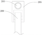
FIG. 2 is a schematic structural view of the built-in box of the present invention;
fig. 3 is a schematic structural diagram of the screw block of the present invention.
In the figure: 1. a flow device; 101. an equipment box; 102. a device base; 103. an air intake duct; 104. an air intake fan; 105. an air outlet pipe; 106. an air outlet fan; 107. a liquid containing tank; 108. a water pump; 109. a connecting hose; 2. a processing device; 201. a built-in box; 202. a motor; 203. a lead screw; 204. a bearing seat; 205. a screw block; 206. a cross bar; 207. a rotating shaft; 208. a vertical rod; 209. a chute; 210. a pressure increasing valve; 211. a spray head; 212. a connecting plate; 213. a filter screen; 214. drying the net; 215. an activated carbon adsorption net.
Detailed Description
The technical solution of the present invention is further specifically described below by way of examples and with reference to the accompanying drawings.
Example (b): an exhaust gas treatment device used in a printing and dyeing process, as shown in fig. 1-3, comprises a flow device 1 and a treatment device 2, wherein the treatment device 2 is fixedly arranged inside the flow device 1.
Flow device 1 includes equipment box 101, the bottom fixed mounting of equipment box 101 has device base 102, the intercommunication has inlet channel 103 on the left side outer wall of equipment box 101, the inside fixed mounting of inlet channel 103 has inlet fan 104, the intercommunication has pipeline 105 of giving vent to anger on the right side outer wall of equipment box 101, the inside fixed mounting of pipeline 105 of giving vent to anger has fan 106 of giving vent to anger, the top fixed mounting of equipment box 101 has liquid to hold case 107, the left side that liquid held case 107 has water pump 108 on the top outer wall of equipment box 101, the inside that liquid held case 107 has sodium hypochlorite solution, and the inside lead to pipe that liquid held case 107 is linked together with the end of intaking of water pump 108, the play water end intercommunication of water pump 108 has coupling hose 109, coupling hose 109 runs through the top outer wall of equipment box 101 and the junction leakproofness is good.
The processing device 2 comprises a built-in box 201, the built-in box 201 is fixedly arranged on the inner wall of the top inside the equipment box 101, a motor 202 is fixedly arranged at the top end of the inner wall of the left side inside the built-in box 201, a lead screw 203 is fixedly arranged on the output end of the motor 202, a bearing seat 204 is fixedly arranged at the joint of one end of the lead screw 203 far away from the motor 202 and the inner wall of the right side of the built-in box, a screw block 205 is movably arranged on the outer wall of the lead screw 203, a thread meshed with the screw block 205 is arranged on the contact surface of the screw block 205 and the lead screw 203, a vertical rod 208 is movably arranged at the bottom end of the screw block 205, a groove is formed in the bottom end of the screw block 205, a fixed shaft penetrates through and is movably connected with the top end of the vertical rod 208, a cross rod 206 is fixedly arranged on the inner walls of the left, the rotating shaft 207 penetrates through the vertical rod 208 and is movably connected with the vertical rod 208, the vertical rod 208 penetrates through the sliding groove 209 and is movably connected with the sliding groove, a pressure increasing valve 210 is fixedly installed at one end, away from the screw block 205, of the vertical rod 208, a connecting hose 109 is communicated with a water inlet end of the pressure increasing valve 210, a spray head 211 is fixedly installed at a water outlet end of the pressure increasing valve 210, a connecting plate 212 is fixedly installed at the left end of the outer wall of the bottom of the built-in box 201, the connecting hose 109 penetrates through the connecting plate 212 and is movably connected with the connecting plate 212, a filter screen 213 is fixedly installed on the outer wall of the right side of the connecting plate 212, a drying screen 214 is fixedly installed on the right side of the outer wall of the bottom of the built-in box 201, one ends, away from the outer wall of the built-in box 201, of the.
The utility model discloses a practical principle: the waste gas enters the equipment box 101 from the inlet pipeline 103 under the combined action of the inlet fan 104 and the outlet fan 106, and is discharged through the outlet pipeline 105 after being treated in the equipment box 101. In equipment box 101, by filter screen 213 filter the solid particle in the waste gas earlier, then shower nozzle 211 spouts sodium hypochlorite solution and disinfects waste gas, carries out drying process by drying net 214 to waste gas next, and activated carbon adsorbs net 215 adsorbs waste gas at last, and equipment box 101 is handled waste gas through four structures for waste gas treatment is thorough. Water pump 108 pumps the sodium hypochlorite solution in liquid holding box 107 to pressure increasing valve 210 through connecting hose 109, and shower nozzle 211 blowout sodium hypochlorite solution disinfects waste gas under pressure increasing valve 210's pressure boost effect. The motor 202 is started, the motor 202 is controlled to rotate forwards, the screw rod 203 drives the screw block 205 to move rightwards, and therefore the vertical rod 208 is driven to swing along the pointer by taking the rotating shaft 207 as the center, and the spray head 211 is driven to swing clockwise; similarly, the control motor 202 rotates counterclockwise to drive the spray head 211 to swing counterclockwise, so that the spray head 211 can swing left and right, the action range of the spray head 211 is enlarged, and the disinfection efficiency is improved.
Finally, it should be noted that the above embodiments are merely representative examples of the present invention. Obviously, the present invention is not limited to the above-described embodiments, and many modifications are possible. Any simple modification, equivalent change and modification made to the above embodiments according to the technical spirit of the present invention should be considered as belonging to the protection scope of the present invention.
Claims (8)
1. An exhaust gas treatment device used in a printing and dyeing process, comprising a flow device (1) and a treatment device (2), characterized in that: a processing device (2) is fixedly arranged in the flowing device (1);
the flowing device (1) comprises an equipment box (101), a device base (102) is fixedly mounted at the bottom of the equipment box (101), an air inlet pipeline (103) is communicated with the outer wall of the left side of the equipment box (101), an air inlet fan (104) is fixedly mounted inside the air inlet pipeline (103), an air outlet pipeline (105) is communicated with the outer wall of the right side of the equipment box (101), an air outlet fan (106) is fixedly mounted inside the air outlet pipeline (105), a liquid containing box (107) is fixedly mounted at the top of the equipment box (101), a water pump (108) is fixedly mounted on the outer wall of the top of the equipment box (101) at the left side of the liquid containing box (107), and a water outlet end of the water pump (108) is communicated with a connecting hose (109);
the processing device (2) comprises a built-in box (201), a motor (202) is fixedly mounted at the top end of the inner wall of the left side in the built-in box (201), a lead screw (203) is fixedly mounted at the output end of the motor (202), a bearing seat (204) is fixedly mounted at the joint of one end, far away from the motor (202), of the lead screw (203) and the inner wall of the right side of the built-in box (201), a screw block (205) is movably mounted on the outer wall of the lead screw (203), a vertical rod (208) is movably mounted at the bottom end of the screw block (205), a transverse rod (206) is fixedly mounted on the inner walls of the left side and the right side of the built-in box (201) below the motor (202), a rotating shaft (207) is fixedly mounted on the outer wall right in front of the transverse rod (206), a sliding groove (209) is formed in the outer wall of the bottom of the built-in box (201), fixed mounting has shower nozzle (211) on the play water end of booster valve (210), the left end fixed mounting of built-in case (201) bottom outer wall has connecting plate (212), fixed mounting has filter screen (213) on the right side outer wall of connecting plate (212), the right side fixed mounting of built-in case (201) bottom outer wall has drying net (214), the right side of drying net (214) fixed mounting has activated carbon adsorption net (215) between the upper and lower end outer wall of equipment box (101).
2. An apparatus for treating exhaust gas from a printing process according to claim 1, wherein: the inside that liquid held case (107) holds has sodium hypochlorite solution, and the inside that liquid held case (107) leads to pipe to be linked together with the end of intaking of water pump (108).
3. An apparatus for treating exhaust gas from a printing process according to claim 1, wherein: the connecting hose (109) penetrates through the outer wall of the top of the equipment box (101), and the sealing performance of the connecting position is good; the connecting hose (109) penetrates through the connecting plate (212) and is movably connected with the connecting plate.
4. An apparatus for treating exhaust gas from a printing process according to claim 1, wherein: the built-in box (201) is fixedly arranged on the inner wall of the top of the interior of the equipment box (101).
5. An apparatus for treating exhaust gas from a printing process according to claim 1, wherein: the rotating shaft (207) penetrates through the vertical rod (208) and is movably connected with the vertical rod, and the vertical rod (208) penetrates through the sliding groove (209) and is movably connected with the sliding groove.
6. An apparatus for treating exhaust gas from a printing process according to claim 1, wherein: one end of the connecting hose (109), which is far away from the water pump (108), is communicated with the water inlet end of the pressure increasing valve (210).
7. An apparatus for treating exhaust gas from a printing process according to claim 1, wherein: one ends, far away from the outer wall of the built-in box (201), of the filter screen (213) and the drying screen (214) are fixedly connected with the inner wall of the equipment box (101).
8. An apparatus for treating exhaust gas from a printing process according to claim 1, wherein: the contact surface of the screw block (205) and the screw rod (203) is provided with threads meshed with the screw block, the bottom end of the screw block (205) is provided with a groove, a fixed shaft is arranged in the groove, and the fixed shaft penetrates through the top end of the vertical rod (208) and is movably connected with the vertical rod.
Priority Applications (1)
| Application Number | Priority Date | Filing Date | Title |
|---|---|---|---|
| CN201920532779.XU CN209967946U (en) | 2019-04-18 | 2019-04-18 | Be used for printing and dyeing in-process exhaust-gas treatment equipment |
Applications Claiming Priority (1)
| Application Number | Priority Date | Filing Date | Title |
|---|---|---|---|
| CN201920532779.XU CN209967946U (en) | 2019-04-18 | 2019-04-18 | Be used for printing and dyeing in-process exhaust-gas treatment equipment |
Publications (1)
| Publication Number | Publication Date |
|---|---|
| CN209967946U true CN209967946U (en) | 2020-01-21 |
Family
ID=69258473
Family Applications (1)
| Application Number | Title | Priority Date | Filing Date |
|---|---|---|---|
| CN201920532779.XU Active CN209967946U (en) | 2019-04-18 | 2019-04-18 | Be used for printing and dyeing in-process exhaust-gas treatment equipment |
Country Status (1)
| Country | Link |
|---|---|
| CN (1) | CN209967946U (en) |
Cited By (1)
| Publication number | Priority date | Publication date | Assignee | Title |
|---|---|---|---|---|
| CN111701361A (en) * | 2020-06-08 | 2020-09-25 | 顾伟国 | Exhaust treatment device for cement production |
-
2019
- 2019-04-18 CN CN201920532779.XU patent/CN209967946U/en active Active
Cited By (1)
| Publication number | Priority date | Publication date | Assignee | Title |
|---|---|---|---|---|
| CN111701361A (en) * | 2020-06-08 | 2020-09-25 | 顾伟国 | Exhaust treatment device for cement production |
Similar Documents
| Publication | Publication Date | Title |
|---|---|---|
| CN108619866A (en) | It is a kind of for acid gas-containing, dust particles exhaust gas front-end purification unit | |
| CN211112629U (en) | Even high temperature water conservation dyeing machine of dyeing is used in knitwear printing and dyeing | |
| CN208626992U (en) | A kind of exhaust gas purification and treatment device | |
| CN208694518U (en) | Energy-saving printing and dyeing emission-control equipment | |
| CN209967946U (en) | Be used for printing and dyeing in-process exhaust-gas treatment equipment | |
| CN204656264U (en) | A kind of emission-control equipment of rinsing type | |
| CN210495902U (en) | Desulfurization dust removal treatment clarification plant | |
| CN104841234A (en) | Washing type waste gas treatment device | |
| CN208406587U (en) | A kind of chemical industry acid mist purifying tower | |
| CN216770217U (en) | Waste gas recovery device for metal waste roasting furnace | |
| CN206404577U (en) | A kind of water reducer production line waste gas treatment equipment | |
| CN212491970U (en) | Exhaust treatment device for chemical industry reation kettle convenient to particulate matter filters | |
| CN211133382U (en) | Workshop waste gas dust collector | |
| CN208678736U (en) | It is a kind of for acid gas-containing, the front-end purification unit of the exhaust gas of dust particles | |
| CN208583234U (en) | A kind of dry cell raw material agitator with purification device | |
| CN210079120U (en) | High-efficient dust collector for industrial equipment | |
| CN107051068A (en) | It is a kind of being capable of smoke-purifying, the air cleaning unit of haze | |
| CN108993088B (en) | Printing and dyeing industry exhaust treatment device | |
| CN206631368U (en) | Being capable of smoke-purifying, the air cleaning unit of haze | |
| CN219399582U (en) | Adsorption dryer convenient to clean | |
| CN220310047U (en) | Waste gas circulating water cleaning device | |
| CN221062179U (en) | Waste gas treatment device with photo-oxygen catalytic mechanism | |
| CN212790444U (en) | Environment-friendly spray drying tower exhaust treatment device | |
| CN219149737U (en) | Environment-friendly tail gas treatment tower | |
| CN216986797U (en) | Waste gas purification device capable of circularly treating |
Legal Events
| Date | Code | Title | Description |
|---|---|---|---|
| GR01 | Patent grant | ||
| GR01 | Patent grant |