CN209953595U - Spring splint reverse cutting die - Google Patents
Spring splint reverse cutting die Download PDFInfo
- Publication number
- CN209953595U CN209953595U CN201920601983.2U CN201920601983U CN209953595U CN 209953595 U CN209953595 U CN 209953595U CN 201920601983 U CN201920601983 U CN 201920601983U CN 209953595 U CN209953595 U CN 209953595U
- Authority
- CN
- China
- Prior art keywords
- die
- mould
- plate
- spring clamp
- utility
- Prior art date
- Legal status (The legal status is an assumption and is not a legal conclusion. Google has not performed a legal analysis and makes no representation as to the accuracy of the status listed.)
- Active
Links
Images


Abstract
The utility model relates to a spring clamp plate cuts mould conversely, including the mounting panel, be provided with the mould below the mounting panel, be provided with the lower mould in last mould below, be provided with the edge of a knife board below the lower mould, be provided with the cutter on the edge of a knife board, be provided with spring clamp plate between lower mould and edge of a knife board. The utility model discloses novel structure, easy and simple to handle, the security performance is high, and when not using, the blade closely laminates at the lower mould lateral wall, and no potential safety hazard, when using, and is die-cut more stable.
Description
Technical Field
The utility model relates to a spring clamp plate cuts mould conversely.
Background
As is well known, a die cutter die typically cuts from the top down. The die cutting needs to be matched up and down, and the precision requirement is high. This reality newly provides a reverse die-cut cutting die structure, goes up the mould required precision and hangs down, and die-cut convenience, the stroke is short, simultaneously because the structure has used reverse die-cut method, the blade has obtained fine protection, and the life of improvement has reduceed the required precision simultaneously.
Disclosure of Invention
In view of this, the utility model aims at providing a spring clamp board cuts mould conversely, novel structure, easy and simple to handle, the security performance is high, and when not using, the blade closely laminates at the lower mould lateral wall, does not have the potential safety hazard, and when using, and is die-cut more stable.
The technical scheme of the utility model is that: the utility model provides a spring clamp plate cuts mould conversely, includes the mounting panel, is provided with the mould below the mounting panel, is provided with the lower mould below last mould, is provided with the edge of a knife board below the lower mould, is provided with the cutter on the edge of a knife board, is provided with spring clamp plate between lower mould and edge of a knife board.
Furthermore, a workpiece is fixed between the upper die and the lower die.
Furthermore, a guide sleeve is arranged on the cutting edge plate.
Furthermore, a guide post which can be matched with the guide sleeve is arranged on the lower end face of the lower die.
Compared with the prior art, the beneficial effects of the utility model are that: the utility model discloses novel structure, easy and simple to handle, the security performance is high, and when not using, the blade closely laminates at the lower mould lateral wall, and no potential safety hazard, when using, and is die-cut more stable.
In order to make the aforementioned objects, features and advantages of the present invention comprehensible, embodiments accompanied with figures are described in detail below.
Drawings
Fig. 1 is a schematic structural diagram of an embodiment of the present invention;
fig. 2 is a front view of an embodiment of the present invention;
fig. 3 is a cross-sectional view of an embodiment of the present invention;
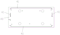
FIG. 4 is a schematic structural view of a knife-edge plate according to an embodiment of the present invention;
FIG. 5 is a top view of a blade plate according to an embodiment of the present invention;
in the figure: 10-mounting a plate; 20-upper die; 30-lower die; 40-a knife-edge plate; 41-a cutter; 50-spring clamp plate; 60-a workpiece; 70-guide sleeve; 80-guide pillar.
Detailed Description
As shown in FIG. 1 ~ 5, a spring clamp plate reverse cutting die comprises a mounting plate 10, an upper die 20 is arranged below the mounting plate 10, a lower die 30 is arranged below the upper die 20, a knife edge plate 40 is arranged below the lower die 30, a cutter 41 is arranged on the knife edge plate 40, and a spring clamp plate 50 is arranged between the lower die 30 and the knife edge plate 40. the upper end surface of the mounting plate 10 is connected with a power mechanism, such as an air cylinder or a hydraulic cylinder, the upper die 20 and the lower die 30 clamp a workpiece 60, during punching, the power mechanism drives the mounting plate 10 to move downwards and drives the upper die 20 and the lower die 30 to clamp the workpiece 60 and move downwards, and during the downward movement of the lower die 30, the spring clamp plate 50 is compressed to expose the cutter 41 on the knife edge plate 40 to punch the workpiece 60.
In the present embodiment, a workpiece 60 is fixed between the upper die 20 and the lower die 30.
In this embodiment, a guide sleeve 70 is further disposed on the knife-edge plate 40.
In this embodiment, a guide post 80 capable of cooperating with the guide sleeve 70 is disposed on the lower end surface of the lower die 30. The cooperation of the guide post 80 and the guide sleeve 70 improves the punching accuracy of the workpiece 60.
Above-mentioned operation flow and software and hardware configuration only do as the preferred embodiment of the utility model discloses a not therefore restrict the patent scope of the utility model, all utilize the utility model discloses the equivalent transform of doing of description and attached drawing content, or directly or indirectly use in relevant technical field, all the same reason is included in the patent protection scope of the utility model.
Claims (4)
1. The utility model provides a spring splint undercut mould which characterized in that: the cutting tool comprises a mounting plate, wherein an upper die is arranged below the mounting plate, a lower die is arranged below the upper die, a cutting edge plate is arranged below the lower die, a cutting tool is arranged on the cutting edge plate, and a spring clamping plate is arranged between the lower die and the cutting edge plate.
2. The spring clamp plate undercut die of claim 1, wherein: a workpiece is fixed between the upper die and the lower die.
3. The spring clamp plate undercut die of claim 1, wherein: the knife edge plate is also provided with a guide sleeve.
4. The spring clamp plate undercut die of claim 3, wherein: and a guide post which can be matched with the guide sleeve is arranged on the lower end face of the lower die.
Priority Applications (1)
| Application Number | Priority Date | Filing Date | Title |
|---|---|---|---|
| CN201920601983.2U CN209953595U (en) | 2019-04-29 | 2019-04-29 | Spring splint reverse cutting die |
Applications Claiming Priority (1)
| Application Number | Priority Date | Filing Date | Title |
|---|---|---|---|
| CN201920601983.2U CN209953595U (en) | 2019-04-29 | 2019-04-29 | Spring splint reverse cutting die |
Publications (1)
| Publication Number | Publication Date |
|---|---|
| CN209953595U true CN209953595U (en) | 2020-01-17 |
Family
ID=69242875
Family Applications (1)
| Application Number | Title | Priority Date | Filing Date |
|---|---|---|---|
| CN201920601983.2U Active CN209953595U (en) | 2019-04-29 | 2019-04-29 | Spring splint reverse cutting die |
Country Status (1)
| Country | Link |
|---|---|
| CN (1) | CN209953595U (en) |
-
2019
- 2019-04-29 CN CN201920601983.2U patent/CN209953595U/en active Active
Similar Documents
| Publication | Publication Date | Title |
|---|---|---|
| CN204819692U (en) | Artifical lawn plastic pad cutting device that punches a hole | |
| CN103639524A (en) | Plate shearer capable of positioning plates accurately | |
| CN209953595U (en) | Spring splint reverse cutting die | |
| CN204353293U (en) | A kind of aluminium section bar punch press | |
| CN203541681U (en) | Novel plate shearing machine | |
| CN204892675U (en) | Automatic corner cut mould is managed in accuracy side | |
| CN210547643U (en) | A cut foot device for optical device integrated into one piece | |
| CN104438587A (en) | Base frame sheet laminating and punching die | |
| CN207271965U (en) | A kind of upper plate suspension hole reinforcing plate cutting piercing die | |
| CN205270526U (en) | Portable fine blanking die of terrace die | |
| CN203330226U (en) | Secondary scrap cutting off device of trimming die | |
| CN104525708A (en) | Side hole punching die of cylinder-shaped workpiece | |
| CN206170212U (en) | Blanking experiment mould | |
| CN212733751U (en) | Punching and cutting die | |
| CN202893908U (en) | Rapidly combined-type bending device | |
| CN203725577U (en) | Level punching machine | |
| CN204799753U (en) | Multipurpose cut -out press | |
| CN209408671U (en) | Glue film punching press mold | |
| CN218015900U (en) | Machining device for installation hole of microporous cutter | |
| CN220574470U (en) | Punching die for material belt | |
| CN216575307U (en) | Shearing mechanism is used in production of high accuracy spring wire | |
| CN215467444U (en) | Punching equipment for cutting in flange production | |
| CN220840520U (en) | Perforating device for self-adhesive paper | |
| CN204353282U (en) | Taper work blanking die | |
| CN216540366U (en) | PCB punching tool |
Legal Events
| Date | Code | Title | Description |
|---|---|---|---|
| GR01 | Patent grant | ||
| GR01 | Patent grant |