CN209942922U - Generating set linkage heat abstractor - Google Patents
Generating set linkage heat abstractor Download PDFInfo
- Publication number
- CN209942922U CN209942922U CN201920974700.9U CN201920974700U CN209942922U CN 209942922 U CN209942922 U CN 209942922U CN 201920974700 U CN201920974700 U CN 201920974700U CN 209942922 U CN209942922 U CN 209942922U
- Authority
- CN
- China
- Prior art keywords
- heat dissipation
- air
- generator set
- generating set
- spring
- Prior art date
- Legal status (The legal status is an assumption and is not a legal conclusion. Google has not performed a legal analysis and makes no representation as to the accuracy of the status listed.)
- Active
Links
- 230000017525 heat dissipation Effects 0.000 claims abstract description 44
- 239000000428 dust Substances 0.000 claims abstract description 35
- XLYOFNOQVPJJNP-UHFFFAOYSA-N water Substances O XLYOFNOQVPJJNP-UHFFFAOYSA-N 0.000 claims abstract description 26
- 238000009413 insulation Methods 0.000 claims description 8
- 238000003466 welding Methods 0.000 claims description 6
- 229910052782 aluminium Inorganic materials 0.000 claims description 3
- XAGFODPZIPBFFR-UHFFFAOYSA-N aluminium Chemical compound [Al] XAGFODPZIPBFFR-UHFFFAOYSA-N 0.000 claims description 3
- 229920005549 butyl rubber Polymers 0.000 claims description 3
- 239000002131 composite material Substances 0.000 claims description 3
- 239000011888 foil Substances 0.000 claims description 3
- 229910052751 metal Inorganic materials 0.000 claims description 3
- 239000002184 metal Substances 0.000 claims description 3
- 210000003437 trachea Anatomy 0.000 abstract description 3
- 230000002093 peripheral effect Effects 0.000 abstract 1
- 230000000694 effects Effects 0.000 description 5
- 238000004140 cleaning Methods 0.000 description 3
- 239000007789 gas Substances 0.000 description 3
- 230000009286 beneficial effect Effects 0.000 description 1
- 238000010586 diagram Methods 0.000 description 1
- 239000002283 diesel fuel Substances 0.000 description 1
- 230000008030 elimination Effects 0.000 description 1
- 238000003379 elimination reaction Methods 0.000 description 1
- 239000002737 fuel gas Substances 0.000 description 1
- 239000003502 gasoline Substances 0.000 description 1
- 238000009434 installation Methods 0.000 description 1
- 230000004048 modification Effects 0.000 description 1
- 238000012986 modification Methods 0.000 description 1
Images


Abstract
The utility model discloses a generating set linkage heat abstractor, including heat dissipation case, dust screen, fan, generating set body and air-blower, the gas outlet has been seted up to the upper end of heat dissipation case, the inside of recess is provided with the spring, the fixed surface of gas outlet has the fixed block, the delivery port has been seted up to the upper surface of heat dissipation case, and the inside of heat dissipation case is provided with generating set body, the surface mounting of generating set body has the water pipe, the inside upper surface mounting of heat dissipation case has the trachea, and the tracheal surface has seted up the air jet, the surface of air jet has been seted up the gas pocket, the air-blower is installed to tracheal right-hand member, the inside surface mounting of heat dissipation case has the pu. This generating set linkage heat abstractor is provided with trachea, air jet and gas pocket, makes the peripheral air flow rate of generating set accelerate to the heat that makes generating set work produce is taken away, and the use of cooperation water pipe has ensured generating set's security more.
Description
Technical Field
The utility model relates to a generating set equipment technical field specifically is a generating set linkage heat abstractor.
Background
The generator set is a device which converts other energy sources such as diesel oil, gasoline, fuel gas and the like into electric energy by the generator in a working mode after being combusted, and the generator set is easy to generate a large amount of heat when working, and the heat is easy to cause danger if not discharged in time.
Most generator set linkage heat dissipation devices have the following problems:
firstly, the dust screen is troublesome to disassemble, the dust screen of most of the existing generator set linkage heat dissipation devices is integrated with the whole device, and the steps of disassembling and cleaning the dust screen are complicated after the dust screen is used for a long time;
secondly, the heat dissipation effect is not good, the heat is only taken out of the generator set in the horizontal direction through the fan, the heat moves upwards, the heat dissipation amount in the horizontal direction is slow, and the temperature at the upper end of the generator set is reduced for a long time.
Therefore, a heat dissipation device for a generator set linkage is provided to solve the above problems.
SUMMERY OF THE UTILITY MODEL
An object of the utility model is to provide a generating set linkage heat abstractor to solve above-mentioned background art and propose present most generating set linkage heat abstractor dust screen and dismantle trouble and the not good problem of radiating effect.
In order to achieve the above object, the utility model provides a following technical scheme: the utility model provides a generating set linkage heat abstractor, includes heat dissipation case, dust screen, fan, generating set body and air-blower, the gas outlet has been seted up to the upper end of heat dissipation case, and the inside of gas outlet sets up flutedly, the inside of recess is provided with the spring, and the right side of spring is provided with the dust screen, the fixed surface of gas outlet has the fixed block, and the lower surface mounting of fixed block has the fan, the delivery port has been seted up to the upper surface of heat dissipation case, and the inside of heat dissipation case is provided with the generating set body, the surface mounting of generating set body has the water pipe, the inside upper surface mounting of heat dissipation case has the trachea, and tracheal surface has seted up the air jet, the surface of air jet is seted up porosely, the air-blower is installed.
Preferably, the diameter of the spring is equal to the diameter of the groove, the spring and the dust screen are connected in a welding mode, and the two groups of springs are symmetrically arranged around the center of the dust screen.
Preferably, the dust screen is connected with the air outlet in a clamping manner through a spring, and the diameter of the dust screen is larger than that of the fan.
Preferably, the connection mode between generating set body and the heat dissipation case is the welding, and the connection mode between generating set body and the water pipe is the block connection.
Preferably, the sound insulation layer is connected with the heat dissipation box in an adhesion mode, and the sound insulation layer is made of a butyl rubber composite metal aluminum foil.
Preferably, the air nozzles are in a gyro shape, are uniformly arranged on the air pipe and are uniformly provided with air holes.
Compared with the prior art, the beneficial effects of the utility model are that: the generator set linkage heat dissipation device;
(1) the spring and the groove are arranged, so that the dust screen can be easily detached and cleaned, the dust-proof function of the dust screen is not influenced, meanwhile, the heat dissipation effect of the whole device cannot be influenced by accumulated dust, and the safety of the generator set is protected;
(2) the water pipe is arranged, and the heat generated by the generator set during working can be directly taken away by the circularly flowing water, so that the generator set cannot be in danger due to overhigh heat generated during working;
(3) the air pipe, the air nozzle and the air hole are arranged, so that the air flow rate around the generator set is accelerated, heat generated by the work of the generator set is taken away, and the safety of the generator set is further ensured by matching with the use of the water pipe;
(4) be provided with the puigging, can give the elimination with a large amount of noises that generating set during operation produced to avoided the staff near generating set during operation for a long time, the condition that a large amount of noises can harm staff's hearing takes place.
Drawings
FIG. 1 is a schematic front sectional view of the present invention;
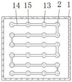
FIG. 2 is a schematic view of the top view of the air tube of the present invention;
FIG. 3 is a schematic view of the fan of the present invention;
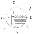
fig. 4 is a schematic structural diagram of a portion a in fig. 1 according to the present invention.
In the figure: 1. a heat dissipation box; 2. an air outlet; 3. a spring; 4. a fixed block; 5. a dust screen; 6. a fan; 7. a water outlet; 8. a groove; 9. a generator set body; 10. a sound insulating layer; 11. a blower; 12. a water pipe; 13. an air jet; 14. an air tube; 15. and (4) air holes.
Detailed Description
The technical solutions in the embodiments of the present invention will be described clearly and completely with reference to the accompanying drawings in the embodiments of the present invention, and it is obvious that the described embodiments are only some embodiments of the present invention, not all embodiments. Based on the embodiments in the present invention, all other embodiments obtained by a person skilled in the art without creative work belong to the protection scope of the present invention.
Referring to fig. 1-4, the present invention provides a technical solution: a generator set linkage heat dissipation device comprises a heat dissipation box 1, an air outlet 2, a spring 3, a fixed block 4, a dustproof net 5, a fan 6, a water outlet 7, a groove 8, a generator set body 9, a sound insulation layer 10, an air blower 11, a water pipe 12, an air jet 13, an air pipe 14 and an air hole 15, wherein the air outlet 2 is formed in the upper end of the heat dissipation box 1, the groove 8 is formed in the air outlet 2, the spring 3 is arranged in the groove 8, the dustproof net 5 is arranged on the right side of the spring 3, the fixed block 4 is fixed on the surface of the air outlet 2, the fan 6 is arranged on the lower surface of the fixed block 4, the water outlet 7 is formed in the upper surface of the heat dissipation box 1, the generator set body 9 is arranged in the heat dissipation box 1, the water pipe 12 is arranged on the surface of the generator set body 9, the surface of the air jet 13 is provided with an air hole 15, the right end of the air pipe 14 is provided with an air blower 11, and the inner surface of the heat dissipation box 1 is provided with a sound insulation layer 10.
The diameter of spring 3 equals with the diameter size of recess 8, and the connected mode between spring 3 and the dust screen 5 is the welding to spring 3 is provided with two sets ofly about 5 centrosymmetric of dust screen, makes things convenient for the dismantlement and the installation of dust screen 5.
The dust screen 5 is connected with the air outlet 2 in a clamping mode through the spring 3, the diameter of the dust screen 5 is larger than that of the fan 6, and dust can be prevented from entering the heat dissipation box 1.
The generator set body 9 and the heat dissipation box 1 are connected by welding, and the generator set body 9 and the water pipe 12 are connected by clamping, so that the temperature of the generator set body 9 can be reduced.
The sound-proof layer 10 and the heat dissipation box 1 are connected in a bonding mode, the sound-proof layer 10 is made of a butyl rubber composite metal aluminum foil, and noise generated during working of the generator set body 9 can be reduced.
The air jet 13 is in a gyro shape, the air jet 13 is uniformly arranged on the air pipe 14, and the air holes 15 are uniformly formed in the air jet 13, so that air around the generator set body 9 can be accelerated, and heat can be taken away.
The working principle is as follows: firstly, as shown in fig. 1 and 4, after the dust screen 5 works for a period of time, the dust screen 5 needs to be taken down from the whole device for cleaning, the dust screen 5 only needs to be pushed leftwards or rightwards, the spring 3 on the left side or the right side starts to be compressed, the spring 3 on the right side or the left side slides out of the groove 8, and then the dust screen 5 is taken down, when the dust screen 5 needs to be installed, the steps are opposite to the above steps, so that the purpose of conveniently disassembling and cleaning the dust screen 5 is achieved, the dust-proof effect of the dust screen 5 cannot be influenced, and meanwhile, the poor heat dissipation effect of the generator set body 9 caused by too much dust accumulated on the dust screen 5 cannot be caused;
as shown in fig. 1-3, when the generator set body 9 is in operation, firstly, the water pipe 12 is externally connected to an external water source, so that water flows through the water pipe 12 and flows out of the water outlet 7, because the connection mode of the water pipe 12 and the generator set body 9 is a clamping connection, and the water in the water pipe 12 is flowing water, so that a large amount of heat generated by the generator set body 9 during operation is taken away, meanwhile, the blower 11 is turned on, the blower 11 blows external air into the air pipe 14, and the air is blown out from the air holes 15 through the air outlets 13, because the aperture of the air holes 15 is small, the wind speed of the wind escaping from the air holes 15 is higher, the air speed around the generator set body 9 is higher, the heat of the generator set body 9 is taken out from the air outlets 2 more quickly, and meanwhile, the sound insulation layer 10 absorbs most of noise of the generator set body, this is the operation of the heat sink device in conjunction with the generator set, and the details not described in detail in this specification belong to the prior art known to those skilled in the art.
Although the present invention has been described in detail with reference to the foregoing embodiments, it will be apparent to those skilled in the art that modifications may be made to the embodiments or portions thereof without departing from the spirit and scope of the invention.
Claims (6)
1. The utility model provides a generating set linkage heat abstractor, includes heat dissipation case (1), dust screen (5), fan (6), generating set body (9) and air-blower (11), its characterized in that: the air outlet (2) is formed in the upper end of the heat dissipation box (1), a groove (8) is formed in the air outlet (2), a spring (3) is arranged in the groove (8), a dust screen (5) is arranged on the right side of the spring (3), a fixed block (4) is fixed on the surface of the air outlet (2), a fan (6) is arranged on the lower surface of the fixed block (4), a water outlet (7) is formed in the upper surface of the heat dissipation box (1), a generator set body (9) is arranged in the heat dissipation box (1), a water pipe (12) is arranged on the surface of the generator set body (9), an air pipe (14) is arranged on the upper surface of the inner portion of the heat dissipation box (1), an air nozzle (13) is formed in the surface of the air pipe (14), an air hole (15) is formed in the surface of the air nozzle (13), and an air hole (, and a sound insulation layer (10) is arranged on the inner surface of the heat dissipation box (1).
2. The generator set linkage heat dissipation device of claim 1, wherein: the diameter of the spring (3) is equal to that of the groove (8), the spring (3) and the dust screen (5) are connected in a welding mode, and the spring (3) is symmetrically provided with two groups relative to the center of the dust screen (5).
3. The generator set linkage heat dissipation device of claim 1, wherein: the dustproof net (5) is connected with the air outlet (2) in a clamping mode through the spring (3), and the diameter of the dustproof net (5) is larger than that of the fan (6).
4. The generator set linkage heat dissipation device of claim 1, wherein: the generator set body (9) and the heat dissipation box (1) are connected in a welding mode, and the generator set body (9) and the water pipe (12) are connected in a clamping mode.
5. The generator set linkage heat dissipation device of claim 1, wherein: the sound insulation layer (10) is connected with the heat dissipation box (1) in an adhesion mode, and the sound insulation layer (10) is made of butyl rubber composite metal aluminum foil.
6. The generator set linkage heat dissipation device of claim 1, wherein: the air nozzles (13) are in a top shape, the air nozzles (13) are uniformly arranged on the air pipe (14), and the air holes (15) are uniformly formed in the air nozzles (13).
Priority Applications (1)
| Application Number | Priority Date | Filing Date | Title |
|---|---|---|---|
| CN201920974700.9U CN209942922U (en) | 2019-06-26 | 2019-06-26 | Generating set linkage heat abstractor |
Applications Claiming Priority (1)
| Application Number | Priority Date | Filing Date | Title |
|---|---|---|---|
| CN201920974700.9U CN209942922U (en) | 2019-06-26 | 2019-06-26 | Generating set linkage heat abstractor |
Publications (1)
| Publication Number | Publication Date |
|---|---|
| CN209942922U true CN209942922U (en) | 2020-01-14 |
Family
ID=69135884
Family Applications (1)
| Application Number | Title | Priority Date | Filing Date |
|---|---|---|---|
| CN201920974700.9U Active CN209942922U (en) | 2019-06-26 | 2019-06-26 | Generating set linkage heat abstractor |
Country Status (1)
| Country | Link |
|---|---|
| CN (1) | CN209942922U (en) |
Cited By (1)
| Publication number | Priority date | Publication date | Assignee | Title |
|---|---|---|---|---|
| CN112502831A (en) * | 2020-11-16 | 2021-03-16 | 无锡柏鹏科技有限公司 | Sound-insulation heat dissipation equipment for engine of bird-repelling spreading vehicle |
-
2019
- 2019-06-26 CN CN201920974700.9U patent/CN209942922U/en active Active
Cited By (1)
| Publication number | Priority date | Publication date | Assignee | Title |
|---|---|---|---|---|
| CN112502831A (en) * | 2020-11-16 | 2021-03-16 | 无锡柏鹏科技有限公司 | Sound-insulation heat dissipation equipment for engine of bird-repelling spreading vehicle |
Similar Documents
| Publication | Publication Date | Title |
|---|---|---|
| CN209942922U (en) | Generating set linkage heat abstractor | |
| CN210141234U (en) | Dustproof plastic top cover with sound insulation function | |
| CN208656250U (en) | A kind of distribution tank current action protecting device | |
| CN207439645U (en) | A kind of long-distance transport pipes optical fiber leakage monitoring device | |
| CN216016108U (en) | Ceramic equipment control cabinet with good heat dissipation effect | |
| CN202611867U (en) | Air inlet structure of diesel engine generator set | |
| CN213928825U (en) | Noise reduction type sound insulation protective cover for fan | |
| CN204783466U (en) | Air all -in -one that can generate electricity | |
| CN211737590U (en) | Noise reduction auxiliary device for tunnel fan | |
| CN210223056U (en) | Heat dissipation traffic signal lamp | |
| CN208907383U (en) | A kind of diesel generating set heat dissipation noise reduction smoke removing device | |
| CN206206287U (en) | Silencing means | |
| CN207634258U (en) | A kind of sound absorbing air pump device | |
| CN109830362A (en) | A kind of heat dissipation noise reducing apparatus of transformer | |
| CN108194195A (en) | A kind of generator protection system with alarm feedback function for water generating | |
| CN220268010U (en) | Fan protection component of power plant | |
| CN210007106U (en) | Negative ion emission head assembly and sleeve for mounting negative ion emission head | |
| CN207363951U (en) | A kind of wind turbine ventilating duct of structure optimization | |
| CN213845254U (en) | Semiconductor with protection function | |
| CN211693367U (en) | Damping device with fixing function for building construction equipment | |
| CN209838726U (en) | Static adjusting draught fan | |
| CN219034867U (en) | Novel noise reduction generator set | |
| CN210239852U (en) | Noise reduction base of generator | |
| CN210939345U (en) | Robot internal element heat radiation structure | |
| CN216056561U (en) | Heat dissipation and noise reduction assembly and cleaning robot |
Legal Events
| Date | Code | Title | Description |
|---|---|---|---|
| GR01 | Patent grant | ||
| GR01 | Patent grant | ||
| PE01 | Entry into force of the registration of the contract for pledge of patent right | ||
| PE01 | Entry into force of the registration of the contract for pledge of patent right |
Denomination of utility model: A generator set linked heat dissipation device Effective date of registration: 20231117 Granted publication date: 20200114 Pledgee: Bank of China Limited Fu'an sub branch Pledgor: FUJIAN YIHUA ELECTRICAL MACHINERY Co.,Ltd. Registration number: Y2023350000238 |