CN209936776U - Clamp for connecting communication cables - Google Patents
Clamp for connecting communication cables Download PDFInfo
- Publication number
- CN209936776U CN209936776U CN201920784890.8U CN201920784890U CN209936776U CN 209936776 U CN209936776 U CN 209936776U CN 201920784890 U CN201920784890 U CN 201920784890U CN 209936776 U CN209936776 U CN 209936776U
- Authority
- CN
- China
- Prior art keywords
- fixedly connected
- lead screw
- communication cable
- rod
- slider
- Prior art date
- Legal status (The legal status is an assumption and is not a legal conclusion. Google has not performed a legal analysis and makes no representation as to the accuracy of the status listed.)
- Active
Links
Images


Abstract
The utility model discloses an anchor clamps are used in communication cable connection belongs to technical field, the on-line screen storage device comprises a base, two shock attenuation connecting device of base top left side fixedly connected with, shock attenuation connecting device top fixedly connected with lower plate, the base top just is located shock attenuation connecting device's right side fixedly connected with bracing piece, bracing piece middle part outside swing joint has the sliding sleeve, first spout has been seted up along vertical direction to bracing piece inside, the inside slip of first spout is equipped with first slider even, the inside rotation of first spout is equipped with the lead screw even, lead screw top fixed mounting has first rim plate, the lead screw run through first slider and with through threaded connection between the first slider, sliding sleeve left side fixed mounting has the connecting rod, connecting rod bottom fixed mounting has the connecting block, has solved through setting up the frictional force that anti-skidding rubber circle increases anchor clamps and is held between the thing and has easily broken away from by the cramped, And damage to the object to be clamped.
Description
Technical Field
The utility model relates to the field of communication technology, more specifically are communication cable connects and uses anchor clamps.
Background
A device for fixing the object to be processed to a correct position for receiving construction or inspection in the machine manufacturing process, which is also called a fixture (qi a/j ǜ). In a broad sense, any device used to quickly, conveniently and safely mount a workpiece at any stage in a process may be referred to as a jig. Such as welding jigs, inspection jigs, assembly jigs, machine tool jigs, and the like. Among them, the machine tool clamp is the most common, and is often referred to as a clamp for short.
The clamping device of the traditional clamp for connecting the communication cable is poor in clamping effect, the cable is easy to break away in working, the surface of the cable is often damaged due to overlarge force caused by the working of the traditional clamp for connecting the communication cable, the clamp is very inconvenient to use, and the clamp for connecting the communication cable is designed for solving the problem.
SUMMERY OF THE UTILITY MODEL
1. Technical problem to be solved
To the problem that exists among the prior art, the utility model aims to provide a communication cable is connected and is used anchor clamps possesses that the centre gripping is effectual, prevents that the cable from damaging, and convenient to use's advantage has solved that traditional anchor clamps centre gripping effect is poor, during operation cable fragile, awkward problem.
2. Technical scheme
In order to solve the above problems, the utility model adopts the following technical proposal.
A clamp for connecting communication cables comprises a base, wherein two shock absorption connecting devices are fixedly connected to the left side of the top of the base, a lower clamping plate is fixedly connected to the top of each shock absorption connecting device, a supporting rod is fixedly connected to the top of the base and positioned on the right side of each shock absorption connecting device, a sliding sleeve is movably connected to the outer side of the middle of the supporting rod, a first sliding groove is formed in the supporting rod in the vertical direction, a first sliding block is arranged in the first sliding groove in a sliding mode, a lead screw is rotatably connected to the inner part of the first sliding groove, a first wheel disc is fixedly arranged at the top of the lead screw, the lead screw penetrates through the first sliding block and is connected with the first sliding block through threads, a connecting rod is fixedly arranged on the left side of the sliding sleeve, a connecting block is fixedly arranged at the, the threaded rod bottom swing joint has the second slider, second slider bottom fixedly connected with punch holder.
Preferably, a rotating block is movably mounted at the joint of the threaded rod and the connecting rod, a threaded groove is formed in the inner side of the rotating block, a bearing is fixedly connected inside the rotating block, and the threaded rod is in threaded connection with the rotating block through the threaded groove.
Preferably, the equal fixed mounting in the left and right sides of the relative one side of punch holder and lower plate has the bolt, bolt and punch holder and lower plate outer wall handing-over department movable mounting respectively have screw, gasket, the one end that the screw was kept away from to the bolt runs through punch holder and lower plate and fixedly connected with anti-skidding rubber circle respectively, the inside wall that anti-skidding rubber circle passes through bolt fixed mounting and punch holder and lower plate.
Preferably, a limiting plate is fixedly mounted at the top of the supporting rod, and the screw rod penetrates through the limiting plate and is in threaded connection with the limiting plate.
Preferably, the threaded sleeves are mounted at the outer side of the screw rod and located at the upper end and the lower end of the first sliding groove.
Preferably, the damping connecting device is internally and fixedly provided with a damping spring.
Preferably, the left side and the right side of the first sliding block are fixedly provided with support plates, and one side of each support plate, which is far away from the first sliding block, is fixedly connected to the inner wall of the sliding sleeve.
3. Advantageous effects
Compared with the prior art, the utility model has the advantages of:
(1) put into lower plate department with the communication cable, lower plate bottom fixed mounting has the shock attenuation connecting device to be used for fixing the lower plate and has improved the stability of anchor clamps on the base, the inside fixed mounting of shock attenuation connecting device has the spring can play the shock attenuation effect simultaneously, then it drives the slider that the lead screw rotates inside messenger's sliding sleeve and removes along vertical direction to rotate first rim plate, sliding sleeve left side fixedly connected with connecting rod, the height that the connecting rod just can be adjusted to the rotation lead screw, rotate the turning block after that, it rotates to drive the threaded rod through the turning block, threaded rod threaded connection has the second slider, second slider bottom fixedly connected with punch holder, the purpose of highly reacing the centre gripping through rotating the turning block just can adjust the punch holder.
(2) The friction force between the clamp and the clamped object in the clamping process can be increased by arranging the anti-slip rubber ring, and the situation that the clamped object is separated from the clamp is avoided.
(3) The height of the sliding sleeve is limited by installing a limiting plate.
(4) The screw rod is positioned by installing the threaded sleeve, so that the situation that the screw rod deviates during working is avoided.
(5) The damping connecting device is internally provided with a spring, and can play a damping effect
Drawings
Fig. 1 is a schematic structural view of the clamping device of the present invention;
FIG. 2 is a schematic view of the entire structure of FIG. 1 at B according to the present invention;
FIG. 3 is a schematic view of the overall structure of the utility model at A in FIG. 1;
FIG. 4 is a cross-sectional view of the support rod of the present invention;
FIG. 5 is a cross-sectional view of the upper clamp plate and the connecting rod of the present invention;
fig. 6 is a schematic cross-sectional structure view of the support rod of the present invention.
The reference numbers in the figures illustrate:
1. a base; 2. a support bar; 3. a shock-absorbing connecting device; 4. a lower splint; 5. an upper splint; 6. connecting blocks; 7. a connecting rod; 8. rotating the block; 9. a thread groove; 10. a bearing; 11. a threaded rod; 12. a first wheel disc; 13. a lead screw; 14. a limiting plate; 15. a sliding sleeve; 16. an anti-slip rubber ring; 17. a bolt; 18. a screw; 19. a gasket; 20. a first slider; 21. a first chute; 22. a second chute; 23. a second slider; 24. a spring.
Detailed Description
The technical solution in the embodiment of the present invention will be clearly and completely described below with reference to the accompanying drawings in the embodiment of the present invention; obviously, the described embodiments are only a part of the embodiments of the present invention, and not all embodiments, and all other embodiments obtained by those skilled in the art without any inventive work are within the scope of the present invention based on the embodiments of the present invention.
In the description of the present invention, it should be noted that the terms "upper", "lower", "inner", "outer", "top/bottom", and the like indicate orientations or positional relationships based on the orientations or positional relationships shown in the drawings, and are only for convenience of description and simplification of description, but do not indicate or imply that the device or element referred to must have a specific orientation, be constructed in a specific orientation, and be operated, and thus, should not be construed as limiting the present invention. Furthermore, the terms "first" and "second" are used for descriptive purposes only and are not to be construed as indicating or implying relative importance.
In the description of the present invention, it is to be noted that, unless otherwise explicitly specified or limited, the terms "mounted", "provided", "sleeved/connected", "connected", and the like are to be understood in a broad sense, such as "connected", which may be fixedly connected, detachably connected, or integrally connected; can be mechanically or electrically connected; they may be connected directly or indirectly through intervening media, or they may be interconnected between two elements. The specific meaning of the above terms in the present invention can be understood in specific cases to those skilled in the art.
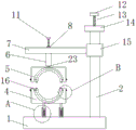
Referring to fig. 1-6, a clamp for connecting a communication cable comprises a base 1, two shock absorption connecting devices 3 are fixedly connected to the left side of the top of the base 1, a lower clamp plate 4 is fixedly connected to the top of the shock absorption connecting device 3, the situation that the lower clamp plate 4 is damaged due to overweight of a clamped object can be avoided by arranging the shock absorption connecting device 3, a support rod 2 is fixedly connected to the right side of the top of the base 1 and positioned on the shock absorption connecting device 3, a sliding sleeve 15 is movably connected to the outer side of the middle of the support rod 2, a first sliding groove 21 is formed in the support rod 2 along the vertical direction, a first sliding block 20 is slidably connected to the inner portion of the first sliding groove 21, a lead screw 13 is rotatably connected to the inner portion of the first sliding groove 21, a first wheel disc 12 is fixedly installed at the top of the lead screw 13, the lead screw 13, through setting up lead screw 13 in first spout 21 is inside, can make first slider 20 drive sliding sleeve 15 and carry out vertical direction and remove, thereby the height of adjustment connecting rod 7, connecting rod 7 bottom fixed mounting has connecting block 6, second spout 22 has been seted up along vertical direction in connecting block 6 is inside, connecting rod 7 middle part threaded connection has threaded rod 11, 11 bottom swing joint of threaded rod has second slider 23, 23 bottom fixedly connected with punch holder of second slider, set up second slider 23 at 22 inside and fixed connection punch holder 5 of second spout through 11 threaded connection of threaded rod that set up in second spout 22 is inside, come to adjust the vertical height of punch holder 5.
Further, threaded rod 11 and connecting rod 7 junction movable mounting have a turning block 8, thread groove 9 has been seted up to the inboard of turning block 8, the inside fixedly connected with bearing 10 of turning block 8, threaded rod 11 passes through thread groove 9 and 8 threaded connection of turning block, can make threaded rod 11 operate more conveniently through setting up turning block 8 and seting up thread groove 9 on turning block 8, can reduce the frictional force operation between turning block 8 and the threaded rod 11 through installation bearing 10 and get up more laborsavingly.
Further, the equal fixed mounting in the left and right sides of the relative one side of punch holder 5 and lower plate 4 has bolt 17, bolt 17 and punch holder 5 and the handing-over punishment of 4 outer walls of lower plate do not have movable mounting screw 18, gasket 19, the one end that screw 18 was kept away from to bolt 17 runs through punch holder 5 and lower plate 4 and fixedly connected with anti-skidding rubber circle 16 respectively, anti-skidding rubber circle 16 passes through the inside wall of bolt 17 fixed mounting and punch holder 5 and lower plate 4, can increase the frictional force of centre gripping in-process through setting up anti-skidding rubber circle 16, avoids being broken away from by the circumstances that the centre gripping thing breaks away from.
Further, 2 top fixed mounting of bracing piece has limiting plate 14, lead screw 13 run through limiting plate 14 and with limiting plate 14 threaded connection, can restrict the height that sliding sleeve 15 reciprocated through setting up limiting plate 14.
Further, the outside of lead screw 13 and both ends all install threaded sleeve about being located first spout 21, can confirm the position of lead screw 13 through installing threaded sleeve, lead screw 13 skew's the condition when can avoiding using simultaneously.
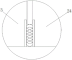
Further, the damping connecting device 3 is fixedly provided with a damping spring 24 inside, and the situation that the lower clamping plate 4 is damaged by an overweight clamped object can be avoided by installing the damping spring 24.
The working principle is as follows: during the use, at first put into the inside wall of lower plate 4 by the centre gripping cable, then rotate lead screw 13, it removes to carry out vertical direction to drive connecting rod 7 through lead screw 13, adjust the height of punch holder 5, then make turning block 8 rotate, thereby it solves the problem that traditional centre gripping instrument operation is complicated to drive the purpose that punch holder 5 moved to reach the centre gripping through turning block 8, increase anchor clamps and solved easily to break away from by the centre gripping thing by the frictional force between the centre gripping thing through setting up anti-skidding rubber circle 16 simultaneously, the condition that is fragile by the centre gripping thing.
The above description is only the preferred embodiment of the present invention; the scope of the present invention is not limited thereto. Any person skilled in the art should also be able to cover the technical scope of the present invention by replacing or changing the technical solution and the improvement concept of the present invention with equivalents and modifications within the technical scope of the present invention.
Claims (7)
1. The utility model provides a communication cable is anchor clamps for connection, includes base (1), its characterized in that: the shock absorption connecting device is characterized in that two shock absorption connecting devices (3) are fixedly connected to the left side of the top of the base (1), a lower clamping plate (4) is fixedly connected to the top of the shock absorption connecting device (3), a supporting rod (2) is fixedly connected to the right side of the top of the base (1) and located on the shock absorption connecting device (3), a sliding sleeve (15) is movably connected to the outer side of the middle of the supporting rod (2), a first sliding groove (21) is formed in the supporting rod (2) along the vertical direction, a first sliding block (20) is slidably connected to the inner portion of the first sliding groove (21), a lead screw (13) is rotatably connected to the inner portion of the first sliding groove (21), a first wheel disc (12) is fixedly installed at the top of the lead screw (13), the lead screw (13) penetrates through the first sliding block (20) and is connected with the first, connecting rod (7) bottom fixed mounting has connecting block (6), second spout (22) have been seted up along vertical direction to connecting block (6) inside, connecting rod (7) middle part threaded connection has threaded rod (11), threaded rod (11) bottom swing joint has second slider (23), second slider (23) bottom fixedly connected with punch holder (5).
2. The jig for connecting a communication cable according to claim 1, wherein: threaded rod (11) and connecting rod (7) junction movable mounting have turning block (8), thread groove (9) have been seted up to the inboard of turning block (8), the inside fixedly connected with bearing (10) of turning block (8), threaded rod (11) are through thread groove (9) and turning block (8) threaded connection.
3. The jig for connecting a communication cable according to claim 1, wherein: the utility model discloses a novel anti-skidding rubber ring, including punch holder (5), lower plate (4), bolt (17), four bolts (17) and punch holder (5) and lower plate (4) outer wall handing-over department respectively movable mounting have screw (18), gasket (19), the one end that screw (18) were kept away from in bolt (17) runs through punch holder (5) and lower plate (4) and fixedly connected with anti-skidding rubber ring (16) respectively, anti-skidding rubber ring (16) are through bolt (17) fixed mounting in the inside wall of punch holder (5) and lower plate (4).
4. The jig for connecting a communication cable according to claim 1, wherein: a limiting plate (14) is fixedly mounted at the top of the supporting rod (2), and the lead screw (13) penetrates through the limiting plate (14) and is in threaded connection with the limiting plate (14).
5. The jig for connecting a communication cable according to claim 1, wherein: threaded sleeves are mounted at the outer side of the lead screw (13) and the upper end and the lower end of the lead screw, which are positioned on the first sliding groove (21).
6. The jig for connecting a communication cable according to claim 1, wherein: and a damping spring (24) is fixedly connected inside the damping connecting device (3).
7. The jig for connecting a communication cable according to claim 1, wherein: supporting plates are fixedly mounted on the left side and the right side of the first sliding block (20), and one side, far away from the first sliding block (20), of each supporting plate is fixedly connected to the inner wall of the sliding sleeve (15).
Priority Applications (1)
| Application Number | Priority Date | Filing Date | Title |
|---|---|---|---|
| CN201920784890.8U CN209936776U (en) | 2019-05-28 | 2019-05-28 | Clamp for connecting communication cables |
Applications Claiming Priority (1)
| Application Number | Priority Date | Filing Date | Title |
|---|---|---|---|
| CN201920784890.8U CN209936776U (en) | 2019-05-28 | 2019-05-28 | Clamp for connecting communication cables |
Publications (1)
| Publication Number | Publication Date |
|---|---|
| CN209936776U true CN209936776U (en) | 2020-01-14 |
Family
ID=69134371
Family Applications (1)
| Application Number | Title | Priority Date | Filing Date |
|---|---|---|---|
| CN201920784890.8U Active CN209936776U (en) | 2019-05-28 | 2019-05-28 | Clamp for connecting communication cables |
Country Status (1)
| Country | Link |
|---|---|
| CN (1) | CN209936776U (en) |
Cited By (4)
| Publication number | Priority date | Publication date | Assignee | Title |
|---|---|---|---|---|
| CN111283575A (en) * | 2020-01-16 | 2020-06-16 | 中科海拓(无锡)科技有限公司 | Adjustable clamping fixing device for industrial detection and operation method thereof |
| CN112936142A (en) * | 2021-03-26 | 2021-06-11 | 安徽德亚电池有限公司 | Frock clamp is used in production of electricity core pole piece |
| CN113042442A (en) * | 2021-03-29 | 2021-06-29 | 安徽宝立华机械设备有限公司 | Auxiliary device for machining threads of petroleum drill rod |
| CN114069354A (en) * | 2021-10-27 | 2022-02-18 | 安徽九工电子设备有限公司 | Terminal machine capable of simultaneously processing multiple wire bundles and using method thereof |
-
2019
- 2019-05-28 CN CN201920784890.8U patent/CN209936776U/en active Active
Cited By (4)
| Publication number | Priority date | Publication date | Assignee | Title |
|---|---|---|---|---|
| CN111283575A (en) * | 2020-01-16 | 2020-06-16 | 中科海拓(无锡)科技有限公司 | Adjustable clamping fixing device for industrial detection and operation method thereof |
| CN112936142A (en) * | 2021-03-26 | 2021-06-11 | 安徽德亚电池有限公司 | Frock clamp is used in production of electricity core pole piece |
| CN113042442A (en) * | 2021-03-29 | 2021-06-29 | 安徽宝立华机械设备有限公司 | Auxiliary device for machining threads of petroleum drill rod |
| CN114069354A (en) * | 2021-10-27 | 2022-02-18 | 安徽九工电子设备有限公司 | Terminal machine capable of simultaneously processing multiple wire bundles and using method thereof |
Similar Documents
| Publication | Publication Date | Title |
|---|---|---|
| CN209936776U (en) | Clamp for connecting communication cables | |
| CN211305608U (en) | But anchor clamps based on angle regulation for machinery | |
| CN215616680U (en) | Automatic change anchor clamps positioning device | |
| CN104308732B (en) | Positioning clamping device and method for positioning and clamping for major axis inner hole grinding | |
| CN218170115U (en) | Finish machining clamp for mounting bracket of machine tool spare and accessory parts | |
| CN209943687U (en) | Fixing device for indoor pipelines | |
| CN213858729U (en) | Clamp assembly for rapid clamping mesopore extrusion grinding machine tool | |
| CN210189079U (en) | Clamping device is used in bearing production of adjustable elasticity | |
| CN210999521U (en) | Diamond fixing and processing equipment | |
| CN211728785U (en) | Piston rod polishes and uses fixing device | |
| CN209811790U (en) | Fine boring clamp for motor shell | |
| CN209919640U (en) | Clamp | |
| CN212794701U (en) | Clamp for valve pipeline | |
| CN210550685U (en) | Clamping device for special aluminum machine | |
| CN213380393U (en) | Spline pitch self-centering lathe fixture | |
| CN211697531U (en) | Fixture for workpiece visual inspection | |
| CN219616872U (en) | Gear machining clamp | |
| CN218837522U (en) | Clamping auxiliary device for machining driven wheel mounting seat | |
| CN220481511U (en) | Auxiliary fixing device with protection architecture | |
| CN216398984U (en) | Cylindrical grinder anchor clamps | |
| CN215787289U (en) | Reversible fixture for wire feeding machine with adjustable upper and lower heights | |
| CN219336923U (en) | Curb plate processing fixed establishment | |
| CN216542728U (en) | Polishing fixing mechanism for hydraulic fittings | |
| CN219380354U (en) | Work piece fixture of cylindrical grinder | |
| CN216802639U (en) | Lathe fixture for matched bolt |
Legal Events
| Date | Code | Title | Description |
|---|---|---|---|
| GR01 | Patent grant | ||
| GR01 | Patent grant |