CN209898675U - Computer rotating cabinet - Google Patents
Computer rotating cabinet Download PDFInfo
- Publication number
- CN209898675U CN209898675U CN201821396963.8U CN201821396963U CN209898675U CN 209898675 U CN209898675 U CN 209898675U CN 201821396963 U CN201821396963 U CN 201821396963U CN 209898675 U CN209898675 U CN 209898675U
- Authority
- CN
- China
- Prior art keywords
- cabinet body
- cabinet
- rotating frame
- display screen
- movable door
- Prior art date
- Legal status (The legal status is an assumption and is not a legal conclusion. Google has not performed a legal analysis and makes no representation as to the accuracy of the status listed.)
- Expired - Fee Related
Links
Images


Landscapes
- Devices For Indicating Variable Information By Combining Individual Elements (AREA)
Abstract
The utility model provides a computer rotary cabinet, which comprises a rectangular first cabinet body and second cabinet bodies arranged at the left side and the right side of the first cabinet body; one side of the second cabinet body is provided with a semicircular part; a rotating frame movably connected with the second cabinet body is arranged in the second cabinet body; the rotating frame is connected with the second cabinet body through a connecting shaft and rotates around the axis of the semicircular part; the outer surface of the rotating frame is matched with the second cabinet body; the first cabinet body and the second cabinet body are separated by a partition plate; three sections of ball sliding rails are arranged on one side of the partition board close to the first cabinet body, and a baffle is arranged on one side close to the second cabinet body; the baffle plate limits the position of the rotating frame; two movable door plates connected with the three sections of ball sliding rails are arranged on the front side of the first cabinet body; the upper end surface of the first cabinet body is provided with a through hole; a display screen lifting device is installed in the first cabinet body and is correspondingly arranged at the position of the through hole; the upper end surface of the display screen lifting device is level with the upper end surface of the first cabinet body; embodies the utility model discloses simple structure, convenient to use saves space, and the structure is unique.
Description
Technical Field
The utility model relates to the field of furniture, in particular to computer rotating cabinet.
Background
The computer cabinet is widely applied to places such as families, companies and the like, the requirements of people on the computer cabinet are higher and higher along with the improvement of the living standard of people, and in order to protect the display screen, a display screen lifting device is designed, so that the display screen can be taken into the cabinet body when not used; however, most of the existing computer cabinets are designed with common storage cabinets for storing articles for daily use, sundries and the like without freshness, and the storage mode generally adopts drawer type or door plates are opened for placing articles, so that space is wasted, a plurality of people can select some pieces of furniture with novel and unique appearance and functions when selecting the furniture, and the storage cabinet is also convenient to use, saves space and is the same when selecting the computer cabinet.
SUMMERY OF THE UTILITY MODEL
The utility model aims at providing a simple structure, convenient to use saves space, the rotatory cabinet of computer of unique structure.
In order to achieve the above object, the present invention provides the following technical solutions:
a computer rotary cabinet comprises a rectangular first cabinet body and second cabinet bodies which are respectively and symmetrically connected to the left side and the right side of the first cabinet body; one side of the second cabinet body, which is far away from the first cabinet body, is provided with a semicircular part; a rotating frame movably connected with the second cabinet body is arranged in the second cabinet body; the rotating frame is connected with the second cabinet body through a connecting shaft and rotates around the axis of the semicircular part; the outer surface of the rotating frame is matched with the second cabinet body; the first cabinet body and the second cabinet body are separated by a partition plate; three sections of ball sliding rails are arranged on one side, close to the first cabinet body, of the partition plate, and a baffle plate is arranged on one side, close to the second cabinet body, of the partition plate; the baffle plate limits the position of the rotating frame; two movable door plates are arranged on the front side of the first cabinet body; the movable door plate is connected with the three sections of ball sliding rails; the upper end surface of the first cabinet body is provided with a rectangular through hole; a display screen lifting device is installed in the first cabinet body and is correspondingly arranged at the position of the through hole; the upper end face of the display screen lifting device is level with the upper end face of the first cabinet body.
For further description of the present invention, the front side of the second cabinet body and the peripheral side of the semicircular portion have openings; the rotating frame comprises a semicircular frame body and a protruding part extending to one side of the frame body; the extending part corresponds to the opening at the front side of the second cabinet body; the extension portion has a handle thereon.
For further description of the present invention, a circular object placing table is fixed in the frame body; the connecting shaft passes through the upper end face and the lower end face of the rack body and the object placing table.
To describe the present invention, a hand pull ring is provided on the movable door plate.
The utility model has the advantages that:
the utility model discloses a set up display screen elevating gear in the first cabinet body, can be when not needing to use the display screen from the first cabinet body to receive down, can protect the display screen, also make the desktop broader, can read and write on the desktop, do more things, the front side of the first cabinet body sets up the movable door plant and is connected with next door through three sections ball slide rails, make the movable door plant can rotate and stretch out and draw back in the second cabinet body in a flexible way, it is more convenient to use; in addition, the second cabinet bodies are arranged on two sides of the first cabinet body, each second cabinet body is provided with a semicircular part, the rotating frame can rotate around the axis of the semicircular part, the rotating frame is sealed in the original state after being installed on the second cabinet body and has no opening, after the rotating frame is rotated by pulling the handle, the frame body of the rotating frame is rotated into the second cabinet body and is limited and blocked by the baffle plate, and at the moment, the opening is formed in the front side of the second cabinet body, so that articles can be placed into the rotating frame for storage, and the space can be saved; the whole structure is unique and novel and is popular.
Drawings
Fig. 1 is a top view of the present invention;
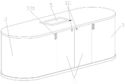
FIG. 2 is an overall structure of the present invention;
fig. 3 is a schematic view of the rotary frame of the present invention being opened;
FIG. 4 is a schematic view of the present invention with the movable door panel opened;
fig. 5 is a structural view of the rotating frame of the present invention.
Detailed Description
The invention is further explained below with reference to the drawings:
as shown in fig. 1 to 5, a computer rotary cabinet comprises a rectangular first cabinet body 1 and second cabinet bodies 2 respectively and symmetrically connected to the left and right sides of the first cabinet body 1; the second cabinet body 2 is provided with a semicircular part 21 at one side far away from the first cabinet body 1; a rotating frame 3 movably connected with the second cabinet body 2 is arranged in the second cabinet body; the rotating frame 3 is connected with the second cabinet body 2 through a connecting shaft 31 and rotates around the axis of the semicircular part 21; the outer surface of the rotating frame 3 is matched with the second cabinet body 2; the front side of the second cabinet 2 and the peripheral side of the semicircular part 21 are provided with openings; the rotating frame 3 comprises a semicircular frame body 32 and a protruding part 33 extending to one side of the frame body 32; the extending part 33 corresponds to the opening at the front side of the second cabinet 2; the protruding part 33 is provided with a handle; a circular object placing table 34 is fixed in the frame body 32; the connecting shaft 31 passes through the upper end surface and the lower end surface of the frame body 32 and the object placing table 34; the interiors of the first cabinet body 1 and the second cabinet body 2 are isolated by a partition plate 4; three sections of ball slide rails 42 are arranged on one side of the partition plate 4 close to the first cabinet body 1, and a baffle plate 41 is arranged on one side close to the second cabinet body 2; the baffle plate 41 limits the position of the rotating frame 3; two movable door panels 11 are arranged on the front side of the first cabinet body 1; the movable door plate 11 is connected with the three sections of ball sliding rails 42; a hand pull ring is arranged on the movable door plate 11; the hand pull ring is convenient to pull out and push in the movable door plate 11; the upper end surface of the first cabinet body 1 is provided with a rectangular through hole; a display screen lifting device 5 is installed in the first cabinet body 1 and is correspondingly arranged at the position of the through hole; the upper end surface of the display screen lifting device 5 is level with the upper end surface of the first cabinet body 1; the display screen lifting device 5 is arranged in the first cabinet body 1, the display screen lifting device 5 is provided with a control button, when the display screen lifting device is not needed to be used, the display screen can be folded downwards from the first cabinet body 1 by pressing the control button, so that the display screen can be protected, the desktop is wider, the desktop can be used for reading and writing and doing more things, the movable door plate 11 is arranged on the front side of the first cabinet body 1 and is connected with the partition wall through the three sections of ball sliding rails 42, the movable door plate 11 can flexibly rotate and stretch in the second cabinet body 2, and the use is more convenient; in addition, set up the second cabinet body 2 in the both sides of the first cabinet body 1, the second cabinet body 2 has semi-circular portion 21, swivel mount 3 can rotate round the axle center of semi-circular portion 21, swivel mount 3 is airtight under the initial condition after installing on the second cabinet body 2, there is not the opening, the pulling handle rotates behind the swivel mount 3, make the support body 32 of swivel mount 3 change over into the second cabinet body 2 in and carry out spacing blockking through baffle 41, the front side of the second cabinet body 2 then has the opening this moment, can put into the support body 32 of swivel mount 3 or put on the thing platform 34 with the thing and save, can save space.
The working principle of the embodiment is as follows:
the display screen lifting device 5 is arranged in the first cabinet body 1, when the display screen lifting device is not needed to be used, the display screen can be folded downwards from the first cabinet body 1 by pressing the control button, so that the display screen can be protected, the desktop is wider, reading and writing can be performed on the desktop, more things can be done, the movable door plate 11 is arranged on the front side of the first cabinet body 1 and is connected with the partition wall through the three sections of ball slide rails 42, the movable door plate 11 can flexibly rotate and can stretch out and draw back in the second cabinet body 2, and the use is more convenient; set up the second cabinet body 2 in the both sides of the first cabinet body 1, the second cabinet body 2 has semi-circular portion 21, swivel mount 3 can rotate round the axle center of semi-circular portion 21, swivel mount 3 is airtight under the initial condition after installing on the second cabinet body 2, there is not the opening, the pulling handle rotates behind the swivel mount 3, make the support body 32 of swivel mount 3 change over into the second cabinet body 2 in and carry out spacing blockking through baffle 41, the front side of the second cabinet body 2 then has the opening this moment, can put into the support body 32 of swivel mount 3 or put and save on the thing platform 34 with the thing pendulum. The above description is not intended to limit the technical scope of the present invention, and any modification, equivalent change and modification made to the above embodiments according to the technical spirit of the present invention are still within the scope of the technical solution of the present invention.
Claims (4)
1. A computer rotating cabinet is characterized in that: the cabinet comprises a rectangular first cabinet body and second cabinet bodies which are symmetrically connected to the left side and the right side of the first cabinet body respectively; one side of the second cabinet body, which is far away from the first cabinet body, is provided with a semicircular part; a rotating frame movably connected with the second cabinet body is arranged in the second cabinet body; the rotating frame is connected with the second cabinet body through a connecting shaft and rotates around the axis of the semicircular part; the outer surface of the rotating frame is matched with the second cabinet body; the first cabinet body and the second cabinet body are separated by a partition plate; three sections of ball sliding rails are arranged on one side, close to the first cabinet body, of the partition plate, and a baffle plate is arranged on one side, close to the second cabinet body, of the partition plate; the baffle plate limits the position of the rotating frame; two movable door plates are arranged on the front side of the first cabinet body; the movable door plate is connected with the three sections of ball sliding rails; the upper end surface of the first cabinet body is provided with a rectangular through hole; a display screen lifting device is installed in the first cabinet body and is correspondingly arranged at the position of the through hole; the upper end face of the display screen lifting device is level with the upper end face of the first cabinet body.
2. The rotary computer cabinet according to claim 1, wherein: the front side of the second cabinet body and the peripheral side of the semicircular part are provided with openings; the rotating frame comprises a semicircular frame body and a protruding part extending to one side of the frame body; the extending part corresponds to the opening at the front side of the second cabinet body; the extension portion has a handle thereon.
3. A computer rotary cabinet according to claim 2, wherein: a round object placing table is fixed in the rack body; the connecting shaft passes through the upper end face and the lower end face of the rack body and the object placing table.
4. The rotary computer cabinet according to claim 1, wherein: the movable door plate is provided with a hand pull ring.
Priority Applications (1)
| Application Number | Priority Date | Filing Date | Title |
|---|---|---|---|
| CN201821396963.8U CN209898675U (en) | 2018-08-27 | 2018-08-27 | Computer rotating cabinet |
Applications Claiming Priority (1)
| Application Number | Priority Date | Filing Date | Title |
|---|---|---|---|
| CN201821396963.8U CN209898675U (en) | 2018-08-27 | 2018-08-27 | Computer rotating cabinet |
Publications (1)
| Publication Number | Publication Date |
|---|---|
| CN209898675U true CN209898675U (en) | 2020-01-07 |
Family
ID=69027981
Family Applications (1)
| Application Number | Title | Priority Date | Filing Date |
|---|---|---|---|
| CN201821396963.8U Expired - Fee Related CN209898675U (en) | 2018-08-27 | 2018-08-27 | Computer rotating cabinet |
Country Status (1)
| Country | Link |
|---|---|
| CN (1) | CN209898675U (en) |
-
2018
- 2018-08-27 CN CN201821396963.8U patent/CN209898675U/en not_active Expired - Fee Related
Similar Documents
| Publication | Publication Date | Title |
|---|---|---|
| CN209898675U (en) | Computer rotating cabinet | |
| CN203493132U (en) | Rotatable drawer cabinet | |
| CN206062544U (en) | A kind of multifunctional storage tea table | |
| CN201668245U (en) | Simple sliding storage rack | |
| CN202919405U (en) | Multimedia platform | |
| CN104873000A (en) | Human engineering teaching equipment and control method thereof | |
| CN210809805U (en) | Novel double-drawer computer desk with multilayer structure | |
| CN204450483U (en) | Combined tool cabinet | |
| CN203646796U (en) | Desk-chest | |
| CN203004933U (en) | Four-foot paint box | |
| CN209983895U (en) | Cabinet is accomodate to multi-functional cashier | |
| CN213282133U (en) | Rotatable wall type storage rack | |
| CN201127452Y (en) | Turnover type display cabinet | |
| CN206238665U (en) | Parcel tray | |
| CN211323802U (en) | Multifunctional desktop office storage box | |
| CN203986735U (en) | A kind of multi-media platform | |
| CN202653586U (en) | Multifunctional tea table | |
| CN211673228U (en) | TV bench of rotatable storing | |
| CN209171678U (en) | Mobile whole kitchen furniture | |
| CN201403798Y (en) | Convenience desk | |
| CN204378349U (en) | A kind of office desk | |
| CN218683245U (en) | Storage mechanism of learning table for children | |
| CN214759967U (en) | Environment-friendly solid wood bookshelf | |
| CN219537798U (en) | Teaching material strorage device | |
| CN219645331U (en) | Household combined cabinet |
Legal Events
| Date | Code | Title | Description |
|---|---|---|---|
| GR01 | Patent grant | ||
| GR01 | Patent grant | ||
| CP01 | Change in the name or title of a patent holder |
Address after: No.2 Tangdu Road, songbotang village, Changping Town, Dongguan City, Guangdong Province 523000 Patentee after: Dongguan Yipeng Smart Home Co.,Ltd. Address before: No.2 Tangdu Road, songbotang village, Changping Town, Dongguan City, Guangdong Province 523000 Patentee before: DONGGUAN YIPENG INTELLIGENT TECHNOLOGY Co.,Ltd. |
|
| CP01 | Change in the name or title of a patent holder | ||
| CF01 | Termination of patent right due to non-payment of annual fee |
Granted publication date: 20200107 Termination date: 20210827 |
|
| CF01 | Termination of patent right due to non-payment of annual fee |