CN209896820U - Dust removal motor fan housing - Google Patents
Dust removal motor fan housing Download PDFInfo
- Publication number
- CN209896820U CN209896820U CN201921039257.2U CN201921039257U CN209896820U CN 209896820 U CN209896820 U CN 209896820U CN 201921039257 U CN201921039257 U CN 201921039257U CN 209896820 U CN209896820 U CN 209896820U
- Authority
- CN
- China
- Prior art keywords
- fan housing
- dust removal
- clamping
- housing body
- movable plate
- Prior art date
- Legal status (The legal status is an assumption and is not a legal conclusion. Google has not performed a legal analysis and makes no representation as to the accuracy of the status listed.)
- Active
Links
Images


Abstract
The utility model discloses a dust removal motor fan housing, the inner chamber of fan housing body is equipped with the dust removal board, the draw-in groove has all been seted up to the top and the bottom of dust removal board, the right side of fan housing body top and bottom all is equipped with the card case, the equal fixedly connected with slide bar in both sides of card incasement chamber, the surface cover of slide bar is equipped with the movable plate, the spout with the movable plate looks adaptation is all seted up to the both sides of card incasement chamber, the top of movable plate is equipped with the spring with the junction cover of card case, the bottom of movable plate is equipped with the kelly, the bottom of kelly runs through card case and fan housing body and extends to the inner chamber of fan housing body and the draw-in. The utility model discloses a fan housing body, dust removal board, card case, spring, spout, movable plate, slide bar, handle, swivel nut, screw rod, movable base, kelly and draw-in groove mutually support, can be when dismantling at the dust removal net in the motor fan housing, can play convenient to detach's effect to the dust removal net.
Description
Technical Field
The utility model relates to a motor fan housing technical field specifically is a dust removal motor fan housing.
Background
An Electric machine (also known as "motor") refers to an electromagnetic device that converts or transmits Electric energy according to the law of electromagnetic induction. Denoted in the circuit by the letter M (old standard by D). Its main function is to generate driving torque as power source of electric appliance or various machines. The generator is denoted in the circuit by the letter G. The main function of the generator is to convert mechanical energy into electric energy, and the most common generator at present utilizes heat energy, water energy and the like to drive a generator rotor to generate electricity.
When the motor is used, the motor fan housing needs to be installed for dust removal, when the motor fan housing is used for a long time, the dust removal net in the fan housing needs to be detached and cleaned, however, when the existing dust removal net on the current market is detached, the detaching process of the dust removal net is complex, and therefore the motor fan housing is not convenient for a user to detach the cleaned state.
SUMMERY OF THE UTILITY MODEL
The utility model aims at providing a dust removal motor fan housing possesses the advantage of playing convenient to detach to the net that removes dust, has solved the loaded down with trivial details problem of flow when dismantling of current net that removes dust.
In order to achieve the above object, the utility model provides a following technical scheme: a dust removal motor fan cover comprises a fan cover body, wherein a dust removal plate is arranged in an inner cavity of the fan cover body, clamping grooves are formed in the top and the bottom of the dust removal plate, a clamping box is arranged on the right side of the top and the right side of the bottom of the fan cover body, sliding rods are fixedly connected to the two sides of the inner cavity of the clamping box, a moving plate is sleeved on the surface of each sliding rod, sliding grooves matched with the moving plates are formed in the two sides of the inner cavity of the clamping box, springs are sleeved at the joints of the top of the moving plate and the clamping box, a clamping rod is arranged at the bottom of the moving plate, the bottom of the clamping rod penetrates through the clamping box and the fan cover body and extends to the inner cavity of the fan cover body to be clamped with the clamping grooves in the dust removal plate, a movable base is arranged at the top of the moving plate, a screw rod is movably connected to the inner cavity of, the top of the screw is fixedly connected with a handle.
Preferably, the joint of the bottom of the moving plate and the clamping rod is fixedly connected through a connecting block, and the clamping rod is located at the center of the bottom of the moving plate.
Preferably, the surface of the handle is sleeved with an anti-skidding sleeve, and an inner cavity of the anti-skidding sleeve is fixedly connected with the handle through an adhesive.
Preferably, the joints of the two ends of the spring, the clamping box and the moving plate are fixedly connected in a welding mode.
Preferably, the number of the sliding grooves is two, and the two sliding grooves are symmetrical about the center of the card box.
Compared with the prior art, the beneficial effects of the utility model are as follows:
1. the utility model discloses a fan housing body, dust removal board, card case, spring, spout, movable plate, slide bar, handle, swivel nut, screw rod, activity base, kelly and draw-in groove mutually support, can be when dismantling the dust removal net in the motor fan housing, can play convenient to detach's effect to the dust removal net, avoided current dust removal net when dismantling, the dust removal net is dismantled the flow loaded down with trivial details to the not convenient to use person dismantles abluent situation, is fit for using widely.
2. The utility model can play a role of skid resistance to the handle through the skid-proof sleeve, so that the effect is better when the user uses the utility model, and the falling-off situation of the user when the user uses the utility model is avoided;
through the connecting block, can play fixed effect to the kelly, the kelly effect is better when using like this, has avoided the kelly not hard up situation to appear when using to lead to the kelly situation that drops to appear when using.
Drawings
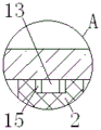
FIG. 1 is a schematic structural view of the present invention;
FIG. 2 is a schematic view of the inner cavity structure of the card box of the present invention;
fig. 3 is a schematic view of a part of an enlarged structure at a in fig. 1 according to the present invention.
In the figure: the wind shield comprises a wind shield body 1, a dust removing plate 2, a clamping box 3, a spring 4, a sliding groove 5, a moving plate 6, a sliding rod 7, an anti-skidding sleeve 8, a handle 9, a threaded sleeve 10, a screw rod 11, a movable base 12, a connecting block 13, a clamping rod 14 and a clamping groove 15.
Detailed Description
The technical solutions in the embodiments of the present invention will be described clearly and completely with reference to the accompanying drawings in the embodiments of the present invention, and it is obvious that the described embodiments are only some embodiments of the present invention, not all embodiments. Based on the embodiments in the present invention, all other embodiments obtained by a person skilled in the art without creative work belong to the protection scope of the present invention.
In the description of the present invention, it should be noted that the terms "upper", "lower", "inner", "outer", "front end", "rear end", "both ends", "one end", "the other end", and the like indicate orientations or positional relationships based on the orientations or positional relationships shown in the drawings, and are only for convenience of description and simplification of description, but do not indicate or imply that the device or element to be referred must have a specific orientation, be constructed in a specific orientation, and be operated, and thus, should not be construed as limiting the present invention. Furthermore, the terms "first" and "second" are used for descriptive purposes only and are not to be construed as indicating or implying relative importance.
In the description of the present invention, it is to be noted that, unless otherwise explicitly specified or limited, the terms "mounted", "provided", "connected", and the like are to be construed broadly, such as "connected", which may be fixedly connected, detachably connected, or integrally connected; can be mechanically or electrically connected; they may be connected directly or indirectly through intervening media, or they may be interconnected between two elements. The specific meaning of the above terms in the present invention can be understood in specific cases to those skilled in the art.
The standard parts used in the application document can be purchased from the market, and can be customized according to the description of the specification and the description of the attached drawings, the specific connection mode of each part adopts conventional means such as mature bolts, rivets, welding and the like in the prior art, and machines, parts and equipment adopt conventional models in the prior art.
The utility model discloses a fan housing body 1, dust removal board 2, card case 3, spring 4, spout 5, movable plate 6, slide bar 7, antiskid cover 8, handle 9, swivel nut 10, screw rod 11, movable base 12, connecting block 13, kelly 14 and draw-in groove 15 part are the parts that general standard spare or technical personnel in the field know, and its structure and principle all are that this technical personnel all can learn through the technical manual or learn through conventional test method.
Referring to fig. 1-3, a dust removal motor fan housing comprises a fan housing body 1, a dust removal plate 2 is arranged in an inner cavity of the fan housing body 1, a slot 15 is formed in the top and the bottom of the dust removal plate 2, a clamping box 3 is arranged on the right side of the top and the bottom of the fan housing body 1, slide bars 7 are fixedly connected to both sides of the inner cavity of the clamping box 3, a moving plate 6 is sleeved on the surface of each slide bar 7, the connection part between the bottom of the moving plate 6 and a clamping rod 14 is fixedly connected through a connecting block 13, and the clamping rod 14 can be fixed through the connecting block 13, so that the clamping rod 14 has a better effect when in use, the situation that the clamping rod 14 is loosened when in use is avoided, the clamping rod 14 falls off when in use, the clamping rod 14 is located at the center of the bottom of the moving plate 6, two sliding grooves 5 matched with the moving plate 6 are formed in both sides of the inner cavity of, and two chutes 5 are centrosymmetric about the card box 3, the joint between the top of the moving plate 6 and the card box 3 is sleeved with a spring 4, the two ends of the spring 4 and the joint between the card box 3 and the moving plate 6 are fixedly connected in a welding manner, the bottom of the moving plate 6 is provided with a clamping rod 14, the bottom of the clamping rod 14 penetrates through the card box 3 and the air hood body 1 and extends to the inner cavity of the air hood body 1 to be clamped with a clamping groove 15 on the dust removing plate 2, the top of the moving plate 6 is provided with a movable base 12, the inner cavity of the movable base 12 is movably connected with a screw rod 11, the top of the screw rod 11 penetrates through and extends to the top of the card box 3, the surface of the screw rod 11 and the joint between the card box 3 are in threaded connection with a threaded sleeve 10, and the top of the screw rod 11 is fixedly connected with a handle 9, the utility model discloses a fan hood body 1, a dust removing plate, Screw rod 11, movable base 12, kelly 14 and draw-in groove 15 mutually support, can be when dismantling the dust removal net in the motor fan housing, can play convenient to detach's effect to the dust removal net, avoided current dust removal net when dismantling, the dust removal net is dismantled the flow loaded down with trivial details, thereby the abluent situation is dismantled to the person of not being convenient for, be fit for using widely, the surperficial cover of handle 9 is equipped with antiskid cover 8, and antiskid cover 8's inner chamber passes through adhesive and handle 9 fixed connection, the utility model discloses an antiskid cover 8 can play skid-proof effect to handle 9, and the user is better when using like this, has avoided the situation that the user appears droing when using.
During the use, rotate handle 9, drive screw rod 11 through handle 9 and rotate, rotate through movable base 12 cooperation screw rod 11, drive screw rod 11 upward movement through swivel nut 10, drive movable plate 6 upward movement through screw rod 11, carry out spacing removal to movable plate 6 through spout 5, move through slide bar 7 cooperation movable plate 6, drive kelly 14 upward movement through movable plate 6, kelly 14 shifts out in the draw-in groove 15 on the dust removal board 2, can dismantle the washing to dust removal board 2, after the washing is accomplished, place the assigned position to dust removal board 2, handle 9 reverses, it can to reset through spring 4 cooperation above-mentioned structure.
In summary, the following steps: this dust removal motor fan housing through fan housing body 1, dust removal board 2, card case 3, spring 4, spout 5, movable plate 6, slide bar 7, handle 9, swivel nut 10, screw rod 11, movable base 12, kelly 14 and draw-in groove 15, has solved the loaded down with trivial details problem of flow when dismantling of current dust removal net.
Although embodiments of the present invention have been shown and described, it will be appreciated by those skilled in the art that changes, modifications, substitutions and alterations can be made in these embodiments without departing from the principles and spirit of the invention, the scope of which is defined in the appended claims and their equivalents.
Claims (5)
1. The utility model provides a dust removal motor fan housing, includes fan housing body (1), its characterized in that: the dust removal fan is characterized in that a dust removal plate (2) is arranged in an inner cavity of the fan housing body (1), clamping grooves (15) are formed in the top and the bottom of the dust removal plate (2), a clamping box (3) is arranged on the right side of the top and the right side of the bottom of the fan housing body (1), sliding rods (7) are fixedly connected to the two sides of the inner cavity of the clamping box (3), a movable plate (6) is sleeved on the surface of each sliding rod (7), sliding grooves (5) matched with the movable plate (6) are formed in the two sides of the inner cavity of the clamping box (3), a spring (4) is sleeved at the joint of the top of the movable plate (6) and the clamping box (3), a clamping rod (14) is arranged at the bottom of the movable plate (6), the bottom of the clamping rod (14) penetrates through the clamping box (3) and the fan housing body (1) and extends to the inner cavity of the fan housing body (1) to be connected with the, the inner chamber swing joint of activity base (12) has screw rod (11), the top of screw rod (11) is run through and is extended to the top of card case (3), the junction threaded connection of the surface of screw rod (11) and card case (3) has swivel nut (10), the top fixedly connected with handle (9) of screw rod (11).
2. The dust removal motor fan housing according to claim 1, wherein: the connecting part of the bottom of the moving plate (6) and the clamping rod (14) is fixedly connected through a connecting block (13), and the clamping rod (14) is positioned at the center of the bottom of the moving plate (6).
3. The dust removal motor fan housing according to claim 1, wherein: the surface of the handle (9) is sleeved with an anti-slip sleeve (8), and the inner cavity of the anti-slip sleeve (8) is fixedly connected with the handle (9) through an adhesive.
4. The dust removal motor fan housing according to claim 1, wherein: the two ends of the spring (4) are fixedly connected with the joints of the clamping box (3) and the moving plate (6) in a welding mode.
5. The dust removal motor fan housing according to claim 1, wherein: the number of the sliding grooves (5) is two, and the two sliding grooves (5) are symmetrical about the center of the clamping box (3).
Priority Applications (1)
| Application Number | Priority Date | Filing Date | Title |
|---|---|---|---|
| CN201921039257.2U CN209896820U (en) | 2019-07-05 | 2019-07-05 | Dust removal motor fan housing |
Applications Claiming Priority (1)
| Application Number | Priority Date | Filing Date | Title |
|---|---|---|---|
| CN201921039257.2U CN209896820U (en) | 2019-07-05 | 2019-07-05 | Dust removal motor fan housing |
Publications (1)
| Publication Number | Publication Date |
|---|---|
| CN209896820U true CN209896820U (en) | 2020-01-03 |
Family
ID=69001872
Family Applications (1)
| Application Number | Title | Priority Date | Filing Date |
|---|---|---|---|
| CN201921039257.2U Active CN209896820U (en) | 2019-07-05 | 2019-07-05 | Dust removal motor fan housing |
Country Status (1)
| Country | Link |
|---|---|
| CN (1) | CN209896820U (en) |
Cited By (1)
| Publication number | Priority date | Publication date | Assignee | Title |
|---|---|---|---|---|
| WO2021248806A1 (en) * | 2020-06-12 | 2021-12-16 | 苏州迎乐机电自动化科技有限公司 | Direct drive motor convenient for speed regulation |
-
2019
- 2019-07-05 CN CN201921039257.2U patent/CN209896820U/en active Active
Cited By (1)
| Publication number | Priority date | Publication date | Assignee | Title |
|---|---|---|---|---|
| WO2021248806A1 (en) * | 2020-06-12 | 2021-12-16 | 苏州迎乐机电自动化科技有限公司 | Direct drive motor convenient for speed regulation |
Similar Documents
| Publication | Publication Date | Title |
|---|---|---|
| CN209896820U (en) | Dust removal motor fan housing | |
| CN114079118B (en) | Layout and signal acquisition equipment for substation storage battery pack | |
| CN210222852U (en) | Office entrance guard equipment convenient to dismantle | |
| CN210798458U (en) | Semicircle cross arm staple bolt that electric power laid usefulness | |
| CN111228906A (en) | Dust cover convenient to wash | |
| CN208158786U (en) | A kind of interchanger of installation easy to disassemble | |
| CN215613310U (en) | Shell water-cooling testing arrangement of motor production usefulness | |
| CN110356506B (en) | PHM-based main engine mounting structure of ship health management equipment | |
| CN212716402U (en) | Hydraulic engineering's emergency ladder of dismouting of being convenient for | |
| CN213561919U (en) | Diamond grinding wheel mounting structure convenient to operation | |
| CN212434774U (en) | Booster battery mounting structure | |
| CN211790923U (en) | Dustproof construction for UPS | |
| CN110854745B (en) | Power distribution network salvagees and uses foreign matter clearing device | |
| CN210171046U (en) | Bellows with dustproof function | |
| CN212660040U (en) | Wiper motor of loader | |
| CN108919909B (en) | Computer machine case convenient to dismantle and wash | |
| CN209599173U (en) | A kind of portable electric machine fault diagnostic tool case | |
| CN211980993U (en) | Socket core piece convenient to dismantle | |
| CN208850758U (en) | Electric power storage hair dryer | |
| CN212660029U (en) | Automobile warm-air motor | |
| CN211422402U (en) | Security door convenient to maintenance | |
| CN215388249U (en) | Convenient sack pulsed dust remover of clearance | |
| CN212138063U (en) | Intelligent switch with electric leakage alarm function | |
| CN209910143U (en) | Ventilation energy-saving equipment of green building | |
| CN212440406U (en) | Dust cover convenient to wash |
Legal Events
| Date | Code | Title | Description |
|---|---|---|---|
| GR01 | Patent grant | ||
| GR01 | Patent grant |