CN209895478U - Quick alarm device for photovoltaic system - Google Patents
Quick alarm device for photovoltaic system Download PDFInfo
- Publication number
- CN209895478U CN209895478U CN201920701144.8U CN201920701144U CN209895478U CN 209895478 U CN209895478 U CN 209895478U CN 201920701144 U CN201920701144 U CN 201920701144U CN 209895478 U CN209895478 U CN 209895478U
- Authority
- CN
- China
- Prior art keywords
- photovoltaic system
- alarm device
- shell main
- installation
- leakage detection
- Prior art date
- Legal status (The legal status is an assumption and is not a legal conclusion. Google has not performed a legal analysis and makes no representation as to the accuracy of the status listed.)
- Expired - Fee Related
Links
Images


Landscapes
- Emergency Alarm Devices (AREA)
- Burglar Alarm Systems (AREA)
Abstract
The utility model discloses a photovoltaic system uses quick alarm device, including shell main part, electric leakage detection probe, singlechip, speaker and light source alarm, electric leakage detection probe is installed to the inside left end of shell main part, and electric leakage detection probe's right side is fixed with the singlechip to the light source alarm is installed to the right-hand member of singlechip, the top of singlechip is fixed with the speaker, and the top of speaker is provided with the dust cover. This quick alarm device for photovoltaic system is provided with two-way lead screw and movable block, and the rotation through two-way lead screw drives the movable block of 2 equal threaded connection in the outside and removes to make the fine drive connecting rod of 2 movable blocks promote the mounting panel, and then be convenient for adjust the high position of mounting panel, so that whole device fine carries out the regulation of height according to the installation region when the installation, the convenient operation to whole device installation work.
Description
Technical Field
The utility model relates to a photovoltaic system technical field specifically is a photovoltaic system uses quick alarm device.
Background
Photovoltaic system refers to the collective name of a series of activities that photovoltaic power generation related to, can use the solar photovoltaic board to carry out the conversion of light energy and electric energy at photovoltaic power generation's in-process, need use quick alarm device at this in-process, whether there is electric leakage phenomenon through the fine detection entire system of quick alarm device, report to the police and handle when having that electric leakage phenomenon can be fine, avoid taking place great loss from this, although the type of quick alarm device on the existing market is various, but still have some weak points, for example:
1. the traditional quick alarm device cannot well adjust the installation height of the whole device in the installation process, and needs to be paved by an external auxiliary device, so that the installation work of the whole device is influenced;
2. when the whole rapid alarm device is used, impurities are easy to accumulate in the dust cover for a period of time, and cannot be cleaned in time, so that the sound transmission of a loudspeaker is influenced;
therefore, the rapid alarm device for the photovoltaic system can well solve the problems.
SUMMERY OF THE UTILITY MODEL
An object of the utility model is to provide a photovoltaic system is with quick alarm device to solve the high position that traditional quick alarm device can not be fine on the existing market that above-mentioned background art provided and adjust the installation according to the installation region, can not be fine dismantle the problem of clearance to the dust cover.
In order to achieve the above object, the utility model provides a following technical scheme: a quick alarm device for a photovoltaic system comprises a shell main body, an electric leakage detection probe, a single chip microcomputer, a loudspeaker and a light source alarm, wherein the electric leakage detection probe is installed at the left end inside the shell main body, the single chip microcomputer is fixed on the right side of the electric leakage detection probe, the light source alarm is installed at the right end of the single chip microcomputer, the loudspeaker is fixed above the single chip microcomputer, a dustproof cover is arranged above the loudspeaker, installation blocks are fixed on two sides of the bottom end of the dustproof cover, installation grooves are formed in the outer sides of the installation blocks, the shell main body is fixed on the outer sides of the installation grooves, limiting rods are arranged inside the installation blocks, connecting ropes are installed on the outer sides of the limiting rods, rotating rods are wound on the bottom ends of the connecting ropes, a bidirectional lead screw is installed inside the bottom end of the shell main body, a moving block is, the bottom of connecting rod is connected with the mounting panel, the outside of light source alarm is provided with the riser, and the right-hand member of riser installs the diaphragm to the left end of riser passes through torsion spring and is connected with the shell bulk phase, the inside wall of diaphragm is installed and is cleaned the pad, reset spring is installed in the outside of gag lever post, and reset spring's the outside is fixed with the shell bulk phase.
Preferably, the gag lever post is provided with 2, and the gag lever post passes through reset spring and constitutes sliding construction with the shell main part to the connected mode of gag lever post and installation piece is the block connection.
Preferably, the middle part of the mounting groove is hollow, and the length of the mounting groove is equal to the longest distance between the 2 mounting blocks.
Preferably, the dust cover is arc-shaped, the inside of the dust cover is mesh-shaped, and the dust cover forms a detachable structure with the mounting groove through the mounting block.
Preferably, the number of the moving blocks is 2, the thread directions in the 2 moving blocks are opposite, and the 2 moving blocks are connected with the bidirectional screw rod in a threaded manner.
Preferably, the connecting rod is connected with the moving block and the mounting plate through movable shafts, and the length of the connecting rod is less than half of that of the connecting rod.
Compared with the prior art, the beneficial effects of the utility model are that: the photovoltaic system uses the rapid alarm device;
(1) the bidirectional screw rod and the moving blocks are arranged, and the two-way screw rod rotates to drive the 2 moving blocks which are in threaded connection at the outer side to move, so that the 2 moving blocks well drive the connecting rods to push the mounting plate, and further the height position of the mounting plate is convenient to adjust, so that the whole device can be well adjusted in height according to the mounting area during mounting, and the operation of mounting work of the whole device is convenient;
(2) the dust cover is fixed with the mounting block and the mounting groove, the mounting block is inserted into the mounting groove, and then the limiting rod is driven to be inserted into the through hole in the mounting block through the force storage of the reset spring, so that the dust cover is conveniently fixed, and similarly, the dust cover can be well disassembled through reverse operation;
(3) install the riser, the riser passes through torsion spring and constitutes reciprocal rotation with the shell main part, and the rotation through the riser drives the diaphragm and cleans the lateral surface of pad to the light source alarm of being convenient for fine is luminous.
Drawings
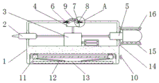
FIG. 1 is a schematic view of the overall main sectional structure of the present invention;
FIG. 2 is an enlarged schematic view of the structure at A of FIG. 1 according to the present invention;
FIG. 3 is a schematic view of the connection between the connection rope and the main body of the housing;
FIG. 4 is a right-view structural diagram of the connection between the vertical plate and the transverse plate of the present invention;
FIG. 5 is an enlarged schematic view of the structure of FIG. 3B according to the present invention;
fig. 6 is the schematic view of the sectional structure of the connection between the vertical plate and the housing body of the present invention.
In the figure: 1. a housing main body; 2. a leakage detection probe; 3. a single chip microcomputer; 4. a speaker; 5. a light source alarm; 6. a limiting rod; 7. mounting grooves; 8. mounting blocks; 9. a dust cover; 10. a bidirectional screw rod; 11. a moving block; 12. a connecting rod; 13. mounting a plate; 14. a vertical plate; 15. a transverse plate; 16. a wiping pad; 17. connecting ropes; 18. a return spring; 19. a rotating rod; 20. a torsion spring.
Detailed Description
The technical solutions in the embodiments of the present invention will be described clearly and completely with reference to the accompanying drawings in the embodiments of the present invention, and it is obvious that the described embodiments are only some embodiments of the present invention, not all embodiments. Based on the embodiments in the present invention, all other embodiments obtained by a person skilled in the art without creative work belong to the protection scope of the present invention.
Referring to fig. 1-6, the present invention provides a technical solution: a quick alarm device for a photovoltaic system comprises a shell main body 1, an electric leakage detection probe 2, a single chip microcomputer 3, a loudspeaker 4, a light source alarm 5, a limiting rod 6, a mounting groove 7, a mounting block 8, a dust cover 9, a bidirectional screw rod 10, a moving block 11, a connecting rod 12, a mounting plate 13, a vertical plate 14, a transverse plate 15, a wiping pad 16, a connecting rope 17, a reset spring 18, a rotating rod 19 and a torsion spring 20, wherein the electric leakage detection probe 2 is mounted at the left end inside the shell main body 1, the single chip microcomputer 3 is fixed on the right side of the electric leakage detection probe 2, the light source alarm 5 is mounted at the right end of the single chip microcomputer 3, the loudspeaker 4 is fixed above the single chip microcomputer 3, the dust cover 9 is arranged above the loudspeaker 4, the mounting block 8 is fixed on both sides of the bottom end of the dust cover 9, the mounting groove 7 is arranged, the inside of installation piece 8 is provided with gag lever post 6, and the outside of gag lever post 6 is installed and is connected rope 17, and the bottom of connecting rope 17 all twines bull stick 19, the bottom internally mounted of shell main part 1 has two-way lead screw 10, and the outside of two-way lead screw 10 is connected with movable block 11, and the bottom of movable block 11 is connected with connecting rod 12, the bottom of connecting rod 12 is connected with mounting panel 13, the outside of light source alarm 5 is provided with riser 14, and riser 14's right-hand member installs diaphragm 15, and riser 14's left end is connected with shell main part 1 through torque spring 20, the inside wall of diaphragm 15 is installed and is cleaned pad 16, reset spring 18 is installed in the outside of gag lever post 6, and reset spring 18's the outside is fixed.
2 limiting rods 6 are arranged, the limiting rods 6 and the shell main body 1 form a sliding structure through a return spring 18, the limiting rods 6 are connected with the mounting block 8 in a clamping mode, and the limiting rods 6 are separated from the mounting block 8 well through sliding of the limiting rods 6, so that the mounting block 8 and the mounting groove 7 can be detached conveniently;
the middle part of the mounting groove 7 is hollow, and the length of the mounting groove 7 is equal to the longest distance between the 2 mounting blocks 8, so that the mounting groove 7 can mount the mounting blocks 8 and the dust cover 9 well;
the dustproof cover 9 is arc-shaped, the inner part of the dustproof cover 9 is in a mesh shape, and the dustproof cover 9 forms a dismounting structure through the mounting block 8 and the mounting groove 7, so that the dustproof cover 9 can be dismounted and cleaned conveniently, and the dustproof cover can be used in the later period conveniently;
the number of the moving blocks 11 is 2, the thread directions in the 2 moving blocks 11 are opposite, and the 2 moving blocks 11 are in threaded connection with the bidirectional lead screw 10, so that the 2 moving blocks 11 can well move inwards or outwards at the same time, and the connecting rod 12 can be pushed conveniently;
the connecting rod 12 is connected with the moving block 11 and the mounting plate 13 through movable shafts, the length of the connecting rod 12 is smaller than one half of the length of the connecting rod 12, and the height position of the mounting plate 13, which is well pushed by the connecting rod 12, is adjusted, so that the whole device is well mounted.
The working principle is as follows: when the rapid alarm device for the photovoltaic system is used, firstly, the whole device is moved into a working area as shown in the attached drawings 1 and 3, after the device reaches the working area, when the whole device needs to be installed, the bidirectional screw rod 10 is manually rotated, the bidirectional screw rod 10 drives the 2 moving blocks 11 which are in threaded connection at the outer side to simultaneously move towards the inner side in the rotating process, the 2 moving blocks 11 push the connecting rod 12 connected with the movable shaft at the bottom end in the moving process, thereby well adjusting the height of the whole device, when the whole device is adjusted to a proper height position, the electric leakage detection probe 2 is fixed with the part to be detected on the outer side, then, the mounting plate 13 and the working area are fixedly mounted through an external tool, so that the whole device can be well mounted and used in different working areas;
after the device is installed, the whole device provides electricity for detection through an internal storage battery, when an electric leakage phenomenon occurs in the whole photovoltaic system, at this time, as shown in figure 1, the electric leakage detection probe 2 well detects the electric leakage phenomenon, then, the electric leakage detection probe 2 transmits the signal to the single chip microcomputer 3, the signal is processed by the single chip microcomputer 3 and is simultaneously transmitted to the loudspeaker 4 and the light source alarm 5, then, the loudspeaker 4 gives out alarm sound, the light source alarm 5 emits light while being opened, so that the light and sound are well matched with each other to give out a quick alarm, when impurities are adhered to the outer side of the light source alarm 5, a worker manually rotates the transverse plate 15, the transverse plate 15 drives the vertical plate 14 to rotate in the rotating process, as shown in figure 1, figure 4 and figure 5, the force is accumulated on the torsion spring 20 through the rotation of the vertical plate 14, then the transverse plate 15 is loosened, at this time, the transverse plate 15 and the vertical plate 14 are driven to rotate reversely together through the accumulated force of the torsion spring 20, so that the transverse plate 15 well drives the wiping pad 16 fixed on the inner wall to wipe the outer wall of the light source alarm 5;
when the dust cover 9 needs to be disassembled and cleaned, as shown in fig. 1-3, the rotating rod 19 is rotated, the rotating rod 19 drives the winding disc on the outer side to simultaneously pull and wind the connecting rope 17 on the side 2 in the rotating process, so that the 2 connecting ropes 17 on the side 2 pull the limiting rod 6, the limiting rod 6 is separated from the mounting block 8, then the dust cover 9 is well taken out from the mounting groove 7 to be cleaned, the electric leakage detection probe 2, the single chip microcomputer 3, the loudspeaker 4 and the light source alarm 5 all belong to the existing mature technologies in the market, and therefore detailed description is not provided in the specification, and the content which is not described in detail in the specification belongs to the existing technology known by professionals in the field.
Although the present invention has been described in detail with reference to the foregoing embodiments, it will be apparent to those skilled in the art that modifications may be made to the embodiments or portions thereof without departing from the spirit and scope of the invention.
Claims (6)
1. The utility model provides a photovoltaic system is with quick alarm device, includes shell main part (1), electric leakage detection probe (2), singlechip (3), speaker (4) and light source alarm (5), its characterized in that: the leakage detection device is characterized in that the leakage detection probe (2) is installed at the left end inside the shell main body (1), the single chip microcomputer (3) is fixed on the right side of the leakage detection probe (2), the light source alarm (5) is installed at the right end of the single chip microcomputer (3), the loudspeaker (4) is fixed above the single chip microcomputer (3), the dustproof cover (9) is arranged above the loudspeaker (4), the installation blocks (8) are fixed on two sides of the bottom end of the dustproof cover (9), the installation groove (7) is formed in the outer side of each installation block (8), the shell main body (1) is fixed on the outer side of each installation groove (7), the limiting rod (6) is arranged inside each installation block (8), the connecting rope (17) is installed on the outer side of each limiting rod (6), the rotating rod (19) is wound on the bottom end of each connecting rope (17), and the bidirectional screw rod (10) is, and the outside of two-way lead screw (10) is connected with movable block (11) to the bottom of movable block (11) is connected with connecting rod (12), the bottom of connecting rod (12) is connected with mounting panel (13), the outside of light source alarm (5) is provided with riser (14), and the right-hand member of riser (14) installs diaphragm (15), and the left end of riser (14) is connected with shell main part (1) through torsion spring (20), the inside wall of diaphragm (15) is installed and is cleaned pad (16), reset spring (18) are installed in the outside of gag lever post (6), and the outside of reset spring (18) is fixed with shell main part (1).
2. The quick alarm device for the photovoltaic system according to claim 1, wherein: the limiting rod (6) is provided with 2, the limiting rod (6) forms a sliding structure with the shell main body (1) through a return spring (18), and the limiting rod (6) is connected with the mounting block (8) in a clamping mode.
3. The quick alarm device for the photovoltaic system according to claim 1, wherein: the middle part of mounting groove (7) is hollow form, and the length of mounting groove (7) equals the longest distance between 2 installation pieces (8).
4. The quick alarm device for the photovoltaic system according to claim 1, wherein: the dustproof cover (9) is arc-shaped, the inner part of the dustproof cover (9) is in a mesh shape, and the dustproof cover (9) forms a dismounting structure with the mounting groove (7) through the mounting block (8).
5. The quick alarm device for the photovoltaic system according to claim 1, wherein: the number of the moving blocks (11) is 2, the thread directions in the 2 moving blocks (11) are opposite, and the 2 moving blocks (11) are in threaded connection with the bidirectional screw rod (10).
6. The quick alarm device for the photovoltaic system according to claim 1, wherein: the connecting rods (12) are connected with the moving blocks (11) and the mounting plates (13) in a movable shaft connection mode, and the length of each connecting rod (12) is less than one half of that of each connecting rod (12).
Priority Applications (1)
| Application Number | Priority Date | Filing Date | Title |
|---|---|---|---|
| CN201920701144.8U CN209895478U (en) | 2019-05-15 | 2019-05-15 | Quick alarm device for photovoltaic system |
Applications Claiming Priority (1)
| Application Number | Priority Date | Filing Date | Title |
|---|---|---|---|
| CN201920701144.8U CN209895478U (en) | 2019-05-15 | 2019-05-15 | Quick alarm device for photovoltaic system |
Publications (1)
| Publication Number | Publication Date |
|---|---|
| CN209895478U true CN209895478U (en) | 2020-01-03 |
Family
ID=69020816
Family Applications (1)
| Application Number | Title | Priority Date | Filing Date |
|---|---|---|---|
| CN201920701144.8U Expired - Fee Related CN209895478U (en) | 2019-05-15 | 2019-05-15 | Quick alarm device for photovoltaic system |
Country Status (1)
| Country | Link |
|---|---|
| CN (1) | CN209895478U (en) |
-
2019
- 2019-05-15 CN CN201920701144.8U patent/CN209895478U/en not_active Expired - Fee Related
Similar Documents
| Publication | Publication Date | Title |
|---|---|---|
| CN210724646U (en) | Support for solar panel | |
| CN209895478U (en) | Quick alarm device for photovoltaic system | |
| CN209470719U (en) | A kind of super energy saving building monitoring device | |
| CN218492901U (en) | A solar protection devices for green building curtain | |
| CN214475548U (en) | Solar energy indicating lamp for road traffic | |
| CN214038960U (en) | Heat supply new forms of energy equipment convenient to adjusting position | |
| CN211718364U (en) | Production site electric quantity monitoring system | |
| CN212109969U (en) | Protection mechanism of flywheel surface flatness intelligent detector | |
| CN212727238U (en) | Network surveillance camera head convenient to overhaul | |
| CN211232341U (en) | Intelligent energy-saving monitoring equipment | |
| CN210293450U (en) | Portable wind-powered electricity generation noise detection device | |
| CN211293013U (en) | Remote control three-phase electric energy meter based on GPRS communication | |
| CN220625418U (en) | High-protection type portable internet of things water meter | |
| CN214097421U (en) | Water environment ecological heavy metal pollution monitoring equipment | |
| CN218039435U (en) | Novel automobile storage battery | |
| CN221177582U (en) | Air compression device with high-efficiency energy-saving function | |
| CN220869011U (en) | Safety protection device for electric overhaul | |
| CN214767141U (en) | On-site monitoring system for weak current engineering | |
| CN219875653U (en) | Solar cell module | |
| CN217503522U (en) | Photovoltaic power generation LED street lamp subassembly | |
| CN220307595U (en) | Intelligent household photoelectric transducer based on photovoltaic system | |
| CN216592321U (en) | Air source heat pump capable of self-adapting to temperature difference change | |
| CN215060814U (en) | Remote monitoring device for operation of solar photovoltaic power generation equipment | |
| CN212226537U (en) | Monitoring device with waterproof dustproof function | |
| CN217406481U (en) | Energy-saving device for fabricated building |
Legal Events
| Date | Code | Title | Description |
|---|---|---|---|
| GR01 | Patent grant | ||
| GR01 | Patent grant | ||
| CF01 | Termination of patent right due to non-payment of annual fee |
Granted publication date: 20200103 Termination date: 20210515 |
|
| CF01 | Termination of patent right due to non-payment of annual fee |