CN2063243U - Projector for uniform-speed circular motion - Google Patents
Projector for uniform-speed circular motion Download PDFInfo
- Publication number
- CN2063243U CN2063243U CN 90202586 CN90202586U CN2063243U CN 2063243 U CN2063243 U CN 2063243U CN 90202586 CN90202586 CN 90202586 CN 90202586 U CN90202586 U CN 90202586U CN 2063243 U CN2063243 U CN 2063243U
- Authority
- CN
- China
- Prior art keywords
- movement
- movement display
- mechanical driving
- uniform
- circular motion
- Prior art date
- Legal status (The legal status is an assumption and is not a legal conclusion. Google has not performed a legal analysis and makes no representation as to the accuracy of the status listed.)
- Withdrawn
Links
- 230000004438 eyesight Effects 0.000 claims description 3
- 238000005096 rolling process Methods 0.000 claims description 3
- 230000000694 effects Effects 0.000 abstract description 3
- 230000000007 visual effect Effects 0.000 abstract description 3
- 238000000926 separation method Methods 0.000 abstract 1
- 239000011324 bead Substances 0.000 description 3
- 238000010586 diagram Methods 0.000 description 3
- 229910000831 Steel Inorganic materials 0.000 description 2
- 239000010959 steel Substances 0.000 description 2
- 230000001360 synchronised effect Effects 0.000 description 2
- 230000004913 activation Effects 0.000 description 1
- 239000000853 adhesive Substances 0.000 description 1
- 230000001070 adhesive effect Effects 0.000 description 1
- 230000007812 deficiency Effects 0.000 description 1
- 238000004519 manufacturing process Methods 0.000 description 1
- 230000001105 regulatory effect Effects 0.000 description 1
- 238000009877 rendering Methods 0.000 description 1
- 230000000087 stabilizing effect Effects 0.000 description 1
Images

Landscapes
- Toys (AREA)
Abstract
The utility model relates to a projector for uniform-speed circular movement, which comprises a movement display portion, a mechanical driving portion and an image drawing portion. The movement display portion and the mechanical driving portion are respectively arranged on the front side and the back side of a middle separation board. An indicating needle is connected with a guiding board by a connection board. A disk gear drives the guiding board to conduct translatory movement by a deflector rod. Meanwhile, the indicating needle synchronously conducts translatory movement. The indicating needle, the disc, the single pendulum ball and the luminous tube of the movement display portion are arranged on the same flat surface of movement visual sense. A hair pencil is arranged on the connection board which can conduct translatory movement. A paper conveying roller is driven by a belt to drive a recording paper belt to act. The simple harmonic vibration of the hair pen and the uniform-speed advancement of the paper belt are combined to draw sine curves. The projector has intuitional demonstration effect and is an ideal tool for class teaching.
Description
The utility model belongs to the instruments used for education field, particularly relates to a kind of instrument of demonstration uniform circular motion lateral projection.
Existing uniform circular motion projector, as the product of the same name that Qianjiang City, Hubei produces, motion is vertically to be placed on the disc level face, the single pendulum bead is periodically controlled by electromagnet, only reflects the swing of one-period and the relative motion relation of circular motion.The weak point of She Zhiing is like this: when the movable body on the disk moved in a circle, its projection was experienced by people's eyesight, and projection is not directly perceived.Simultaneously, can not realize the continuous synchronization motion of single pendulum bead and movable body lateral projection ideally.Do not have image to draw mechanism in addition, can't draw motion video, thereby just can not do quantitatively measuring and calculating and analysis yet.Above-mentioned these factor affecting teaching efficiency.
The purpose of this utility model overcomes the deficiencies in the prior art just, and it is directly perceived to manufacture a kind of observation motion projection, the demonstration teaching aid of single pendulum bead and motion of pointer continuous synchronization and additional visual rendering enginer structure.
The purpose of this utility model is to realize like this.This device comprises that movement display part, mechanical driving part and image describe part.Movement display partly comprises pointer, disk, single pendulum ball and luminotron.Mechanical driving part comprises motor, turbine worm, gear, belt pulley, guide rail and guide plate.Image drawing section branch comprises paper feed roller, paintbrush, recording paper strip.Movement display part and mechanical driving part are separated by median septum.Carousel gear drives guide plate by driving lever and moves as horizontal translation along guide rail, and pointer joins by web joint and guide plate.When the guide plate translation motion, the pointer of front is translation motion synchronously also.Pointer, disk, single pendulum ball and luminotron are in same movement vision plane.Single pendulum is stone-dead when doing, and locatees by electromagnetic actuation.When pointer moves to the relevant position, the outage of control electromagnet, the single pendulum ball just can be synchronized with the movement in company with pointer.Electromagnet is arranged on the accessible solstics of the beat of pointer.Disk is coaxial with carousel gear, and when carousel gear was rotated, disk rotated simultaneously.The intersection point of radius and circumference is positioned on the vertical plane at pointer place all the time on the disk.But paintbrush is installed on the web joint of translation motion, and paper feed roller is by belt gear, and the activation record paper tape moves.Harmonic motion between paintbrush (being synchronized with the movement with luminotron, pointer) and paper tape at the uniform velocity advance and combine, and just can draw out sinusoidal curve.
The utlity model has following advantage:
1. each part of movement display part places in the same visual plane, and pointer (projection line), luminotron (subpoint), paintbrush and single pendulum ball all swing continuously by sinusoidal rule, and the demonstration effect is directly perceived, and classroom teaching effect is good.
2. describe part owing to be provided with image, can write down the sine line of a harmonic motion, this figure line can be for the essence of measuring and calculating and reflection sine principle.
Embodiment of the present utility model is illustrated in conjunction with the accompanying drawings.
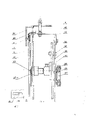
Fig. 1 is a schematic appearance of the present utility model.
Fig. 2 is that image of the present utility model is described structural scheme of mechanism.
Fig. 3 is a machine inner structure synoptic diagram of the present utility model.
Fig. 4 is mechanical drive of the present utility model and movement display parts relationship synoptic diagram.
Fig. 5 is that guide plate of the present utility model and driving lever position concern synoptic diagram.
As shown in the figure, the utility model comprises that movement display part, mechanical driving part and image describe part.Movement display partly comprises pointer [ 1 ], disk [ 2 ], single pendulum ball [ 3 ] and luminotron [ 4 ].Mechanical driving part comprises motor [ 30 ], belt pulley [ 31 ], worm screw [ 21 ], worm gear [ 22 ], mesomerism gear [ 33 ], carousel gear [ 36 ], guide plate [ 34 ] and guide rail [ 37 ].Image drawing section branch comprises that paper feed roller [ 5 ], platen roll [ 6 ], paintbrush [ 7 ], recording paper strip [ 15 ], frame paper bar [ 16 ], roll frame axle [ 17 ] and roll frame [ 18 ].Movement display part and mechanical driving part place the both sides, front and back of median septum [ 27 ] respectively.Disk [ 2 ] is installed in the front end of axle [ 25 ], and axle [ 25 ] passes median septum [ 27 ], on the carousel gear [ 36 ] that the rear end is fixed.Axle sleeve [ 25-1 ] is positioned between disk [ 2 ] and the median septum [ 27 ].Pointer [ 1 ] is connected with guide plate [ 34 ] by web joint [ 26 ], and luminotron [ 4 ] is fixed on the web joint [ 26 ], and guide plate [ 34 ] is placed on the guide rail [ 37 ] by steel ball jackscrew [ 35 ] and steel ball [ 42 ].Mechanical drive is closed: motor [ 30 ]-→ worm screw [ 21 ]-→ worm gear [ 22 ]-→ belt pulley [ 31 ]-→ mesomerism gear [ 33 ]-→ carousel gear [ 36 ].One guide groove [ 34-1 ] is arranged on the guide plate [ 34 ], and the driving lever on the carousel gear [ 40 ] places guide groove [ 34-1 ], and carousel gear [ 36 ] can drive guide plate [ 34 ] by driving lever [ 40 ] and do the horizontal translation motion along guide rail [ 37 ].Web joint [ 26 ] that is connected with guide plate [ 34 ] and the pointer [ 1 ] on the web joint and paintbrush [ 7 ] are done the horizontal translation motion in company with guide plate [ 34 ].Single pendulum ball [ 3 ] is hung on the cable hanger [ 8 ] by cycloid, and cable hanger [ 8 ] is installed on the adjusting lever [ 11 ], by regulating the position of adjusting lever, the height of cable hanger [ 8 ] is met the requirements.The location adhesive of single pendulum ball [ 3 ] realizes by electromagnet [ 13 ].Above the casing [ 28 ] image is housed and describes mechanism.Rolling frame [ 18 ] is installed on the axle [ 17 ].Paper feed roller [ 5 ] is connected with belt pulley [ 31 ] by belt [ 10 ].Belt pulley [ 31 ] rotates, and drives paper feed roller [ 5 ] action, and recording paper strip [ 15 ] places paper feed roller [ 5 ] and platen to roll between [ 6 ] through rolling frame [ 18 ], frame paper bar [ 16 ], paintbrush [ 7 ].Other parts of the present utility model are: electro-magnet switch [ 12 ], motor switch [ 14 ], frame [ 19 ], panel [ 20 ], electromagnet is adjusted screw [ 23 ], transparent window plate [ 24 ], casing [ 28 ], adjusting knob [ 29 ], binding post [ 32 ], back shroud [ 38 ], lead [ 39 ], ring flange [ 41 ].The electronics speed stabilizing that is used for drive motor, electrodeless variable-speed circuit, its wiring board are fixed on (figure part omitted) on the back cabinet.
Claims (3)
1, a kind of uniform circular motion projector, comprise movement display part and mechanical driving part, it is characterized in that casing [28] top is provided with image and describes mechanism, the pointer [1] of movement display part links to each other with guide plate [34] by web joint [26], guide groove [34-1] is arranged on the guide plate [34], and the driving lever [40] on the carousel gear of mechanical driving part [36] is arranged in guide groove [34-1].
2, uniform circular motion projector according to claim 1, it is characterized in that movement display partly comprises pointer [ 1 ], disk [ 2 ], single pendulum ball [ 3 ] and luminotron [ 4 ], they are in same movement vision plane, and movement display part and mechanical driving part place the both sides, front and back of median septum [ 27 ] respectively.
3, uniform circular motion projector according to claim 1, it is characterized in that image describes mechanism and comprise that paper feed roller [ 5 ], platen roll [ 6 ], paintbrush [ 7 ], recording paper strip [ 15 ], frame paper bar [ 16 ], axle [ 17 ], roll frame [ 18 ], rolling frame [ 18 ] is installed on the axle [ 17 ], paintbrush [ 7 ] is installed on the web joint [ 26 ], and paper feed roller [ 5 ] is connected with belt pulley [ 31 ] by belt [ 10 ].
Priority Applications (1)
| Application Number | Priority Date | Filing Date | Title |
|---|---|---|---|
| CN 90202586 CN2063243U (en) | 1990-03-06 | 1990-03-06 | Projector for uniform-speed circular motion |
Applications Claiming Priority (1)
| Application Number | Priority Date | Filing Date | Title |
|---|---|---|---|
| CN 90202586 CN2063243U (en) | 1990-03-06 | 1990-03-06 | Projector for uniform-speed circular motion |
Publications (1)
| Publication Number | Publication Date |
|---|---|
| CN2063243U true CN2063243U (en) | 1990-10-03 |
Family
ID=4883955
Family Applications (1)
| Application Number | Title | Priority Date | Filing Date |
|---|---|---|---|
| CN 90202586 Withdrawn CN2063243U (en) | 1990-03-06 | 1990-03-06 | Projector for uniform-speed circular motion |
Country Status (1)
| Country | Link |
|---|---|
| CN (1) | CN2063243U (en) |
-
1990
- 1990-03-06 CN CN 90202586 patent/CN2063243U/en not_active Withdrawn
Similar Documents
| Publication | Publication Date | Title |
|---|---|---|
| CN105835571B (en) | A kind of electronic blackboard with automatic blackboard eraser | |
| CN106205224A (en) | A kind of distance for dais of imparting knowledge to students rotatable integration projector structure | |
| US3348320A (en) | Phonetic teaching device | |
| CN2063243U (en) | Projector for uniform-speed circular motion | |
| CN214279196U (en) | Novel demonstration device for multimedia | |
| CN201224281Y (en) | Dust-absorbing blackboard eraser apparatus | |
| CN109109520A (en) | Strengthened glass blackboard is used in a kind of teaching | |
| CN106128235B (en) | Vibration and wave motion demonstrator | |
| CN214332234U (en) | A curriculum display device based on pharmacy curriculum | |
| CN207925077U (en) | A kind of ideological and political education propaganda board | |
| CN209183074U (en) | Magnetic Rotation Vector and Simple Harmonic Vibration Demonstrator | |
| CN2565103Y (en) | Electrocontrolled multi-face advertisement lampbox | |
| CN209657588U (en) | A kind of Accounting Course apparatus | |
| CN201526792U (en) | Movable bracket of wall mounting type integrated type multi-media equipment | |
| CN206179332U (en) | Undulant demonstration appearance of vibration | |
| CN108492725A (en) | A kind of product intelligent demonstration instrument of conveniently fast disassembling and installation | |
| CN208848597U (en) | A kind of interaction exhibition equipment | |
| CN223272969U (en) | Integrated force and motion demonstration model display window | |
| CN207711948U (en) | A kind of farm machinery navigation display screen driving mechanism | |
| CN221304114U (en) | Rolling recitation auxiliary device | |
| CN221466251U (en) | Wall-mounted billboard | |
| CN218350700U (en) | Projection transparent display mobile device | |
| CN2346021Y (en) | Simple harmonic oscillation projection demonstration instrument | |
| CN215244015U (en) | Computer software engineering teaching display device | |
| CN215962061U (en) | Broadcasting and hosting is with synthesizing trainer |
Legal Events
| Date | Code | Title | Description |
|---|---|---|---|
| C06 | Publication | ||
| PB01 | Publication | ||
| C14 | Grant of patent or utility model | ||
| GR01 | Patent grant | ||
| C19 | Lapse of patent right due to non-payment of the annual fee | ||
| CF01 | Termination of patent right due to non-payment of annual fee |