CN203690574U - NGFF (Next Generation Form Factor) connector assembly and NGFF connector structure - Google Patents
NGFF (Next Generation Form Factor) connector assembly and NGFF connector structure Download PDFInfo
- Publication number
- CN203690574U CN203690574U CN201420039606.1U CN201420039606U CN203690574U CN 203690574 U CN203690574 U CN 203690574U CN 201420039606 U CN201420039606 U CN 201420039606U CN 203690574 U CN203690574 U CN 203690574U
- Authority
- CN
- China
- Prior art keywords
- ngff
- circuit board
- contact site
- pair
- towards
- Prior art date
- Legal status (The legal status is an assumption and is not a legal conclusion. Google has not performed a legal analysis and makes no representation as to the accuracy of the status listed.)
- Expired - Lifetime
Links
- 238000003032 molecular docking Methods 0.000 claims description 38
- 238000010276 construction Methods 0.000 claims description 30
- 238000005452 bending Methods 0.000 claims description 24
- 230000008878 coupling Effects 0.000 claims description 17
- 238000010168 coupling process Methods 0.000 claims description 17
- 238000005859 coupling reaction Methods 0.000 claims description 17
- 230000000712 assembly Effects 0.000 claims 7
- 238000000429 assembly Methods 0.000 claims 7
- 238000009434 installation Methods 0.000 abstract description 4
- 238000009413 insulation Methods 0.000 abstract 1
- 239000007787 solid Substances 0.000 description 4
- 238000000465 moulding Methods 0.000 description 2
- 230000002787 reinforcement Effects 0.000 description 2
- 230000005540 biological transmission Effects 0.000 description 1
- 238000006243 chemical reaction Methods 0.000 description 1
- 230000000694 effects Effects 0.000 description 1
- 238000005516 engineering process Methods 0.000 description 1
- 238000000034 method Methods 0.000 description 1
- 230000000007 visual effect Effects 0.000 description 1
Images


Abstract
The utility model relates to an NGFF (Next Generation Form Factor) connector assembly and an NGFF connector structure. The NGFF connector structure is used in a circuit board having a pair of positioning holes. The NGFF connector structure comprises an NGFF specification socket which has an insulation body that has a first face and a second face which are facing each other, wherein the first face is provided with a plugging groove and the second face corresponds to the connection of the circuit board, so that the NGFF specification socket is mounted on the circuit board, and the direction of an groove opening of the plugging groove is configured to be perpendicular to a surface of the circuit board. In such a manner, the circuit board can has much area for the installation of electronic parts, and improved use efficiency of the circuit board is thus achieved.
Description
Technical field
The utility model has about a kind of connector, espespecially a kind of NGFF connector assembly and structure thereof.
Background technology
M.2 or claim NGFF (Next Generation Form Factor), it is the new standard standard of solid state hard disc (Solid State Drive, SSD) custom-made in conjunction with many electronics dealers, and can support SATA and PCIe interface.In addition, the volume of NGFF (claim again M.2) standard is compact, power saving and transmission speed fast, and the standard design of different size, can allow SSD application more apply in a flexible way.
Therefore, in electronic installation, be equiped with at present NGFF (claiming M.2 again) connector, peg graft for SSD card (abbreviation of solid state hard disc expansion board), to allow the data acess method of electronic installation evolve as volume is less, speed solid state hard disc (SSD) faster from traditional rigid disk.
But, the notch direction of the inserting groove of NGFF (claiming M.2 again) connector and the surface of circuit board are configured in parallel on the market, allow the SSD card being plugged on NGFF (claiming M.2 again) connector also be configured in parallel with the surface of circuit board, causing circuit board must reserve area is installed with to SSD card, the area that circuit board can mounting electronic parts thus also can reduce, and then affects the service efficiency of circuit board.
Utility model content
The purpose of this utility model, be to provide a kind of NGFF connector assembly and structure thereof, it utilizes the notch direction of inserting groove and the surface of circuit board to be arranged perpendicular, make NGFF connector circuit board around there is the more long-pending energy of multiaspect supplied for electronic part and install, to reach the service efficiency that promotes circuit board.
In order to achieve the above object, the utility model provides a kind of NGFF connector construction, and for a circuit board, this NGFF connector construction comprises:
One NGFF specification socket, there is an insulating body, this insulating body has a relative first surface and one second, this first surface is provided with an inserting groove, the described circuit board of this second correspondence connects, to make this NGFF specification socket be installed on described circuit board, and the notch direction of this inserting groove and the surface of described circuit board are arranged perpendicular.
Further, wherein said circuit board has a pair of location hole, and this second mask has towards a pair of angle extending away from this first surface direction, and corresponding a pair of this location hole of a pair of this angle plugs.
Further, wherein said circuit board has a pair of fixing hole, and this second mask has towards the pair of upright fixed leg extending away from this first surface direction, and the corresponding a pair of described fixing hole of a pair of this upright fixed leg plugs.
Further, wherein this second mask has four jiaos of coupling ends, and a pair of this angle and a pair of this upright fixed leg are disposed at this four jiaos of coupling ends with diagonal way respectively.
Further, wherein in this inserting groove, have one first relative inwall and one second inwall, this NGFF specification socket has along a plurality of the first terminals of this first inner wall arrangement and along a plurality of second terminals of this second inner wall arrangement.
Further, wherein each this first terminal one end has one first contact site, each this second terminal one end has one second contact site, respectively this first contact site and respectively this second contact site be formed in this inserting groove and be opposite each other, each this first contact site has towards one the one V font section of this second contact site bending, and each this second contact site has towards one the 2nd V font section of this first contact site bending.
Further, wherein said circuit board has a plurality of terminal connection parts, each this first terminal other end has one first docking section, each this second terminal other end has one second docking section, respectively this first docking section and respectively this second docking section be exposed to this second, these second both sides has one first ora terminalis of parallel and contiguous this first inwall and one second ora terminalis of parallel and contiguous this second inwall, each this first docking section has towards one the one L font section of this first ora terminalis bending, each this second docking section has towards one the 2nd L font section of this second ora terminalis bending, respectively a L font section and respectively the corresponding described terminal connection part weldering of the 2nd L font section establish.
Further, wherein this inserting groove is offered to this second from this first surface.
The utility model also provides a kind of NGFF connector assembly, comprising:
One circuit board; And
A plurality of NGFF specification sockets, each this NGFF specification socket has an insulating body, this insulating body has a relative first surface and one second, this first surface is provided with an inserting groove, this is second in the face of should circuit board connecting, with order respectively this NGFF specification socket be installed on this circuit board with arrangement mode arranged side by side, and the notch direction of each this inserting groove and the surface of this circuit board are arranged perpendicular.
Further, the plural number that wherein this circuit board has arrangement arranged side by side is to location hole, and each this second mask has towards a pair of angle extending away from this first surface direction, respectively this to angle correspondence, respectively this plugs location hole.
Further, the plural number that wherein this circuit board has arrangement arranged side by side is to fixing hole, and each this second mask has towards the pair of upright fixed leg extending away from this first surface direction, respectively this to upright fixed leg correspondence, respectively this plugs fixing hole.
Further, wherein each this second mask has four jiaos of coupling ends, and a pair of this angle and a pair of this upright fixed leg are disposed at this four jiaos of coupling ends with diagonal way respectively.
Further, wherein in each this inserting groove, have one first relative inwall and one second inwall, each this NGFF specification socket has along a plurality of the first terminals of this first inner wall arrangement and along a plurality of second terminals of this second inner wall arrangement.
Further, wherein each this first terminal one end has one first contact site, each this second terminal one end has one second contact site, respectively this first contact site and respectively this second contact site be formed in this inserting groove and be opposite each other, each this first contact site has towards one the one V font section of this second contact site bending, and each this second contact site has towards one the 2nd V font section of this first contact site bending.
Further, wherein this circuit board has the plural groups terminal connection part of arrangement arranged side by side, each this first terminal other end has one first docking section, each this second terminal other end has one second docking section, respectively this first docking section and respectively this second docking section be exposed to this second, each these second both sides has one first ora terminalis of parallel and contiguous this first inwall and one second ora terminalis of parallel and contiguous this second inwall, each this first docking section has towards one the one L font section of this first ora terminalis bending, each this second docking section has towards one the 2nd L font section of this second ora terminalis bending, respectively a L font section and respectively the 2nd L font section correspondence respectively the weldering of this terminal connection part establish.
Further, wherein each this inserting groove is offered to this second from this first surface.
Further, wherein respectively this NGFF specification socket is arranged in this circuit board with mode longitudinally arranged side by side or mode laterally arranged side by side.
The utility model also has following effect:
The first, the notch direction of inserting groove and the surface of circuit board are arranged perpendicular, make SSD card also be arranged perpendicular with the surface of circuit board, so M.2 NGFF(claims again) specification socket circuit board around need not reserve area and be installed with to SSD card, and then circuit board can mounting electronic parts area change, to promote the service efficiency of circuit board.
The second, the second mask has four jiaos of coupling ends, angle and upright fixed leg are disposed on four jiaos of coupling ends with diagonal way respectively, M.2 NGFF(is claimed again) specification socket can firmly be installed on circuit board by four jiaos of coupling ends, and then the binding ability of reinforcement NGFF connector construction and circuit board.
Three, each first docking section has towards a L font section of the first ora terminalis bending, each second docking section has towards the 2nd L font section of the second ora terminalis bending, the corresponding each terminal connection part weldering of each L font section and each the 2nd L font section is established, to allow NGFF(claim again M.2) weldering of specification socket and circuit board establishes more convenient convenience, and the moulding of a L font section and each the 2nd L font section can stably be supported NGFF(and be claimed again M.2) weight of specification socket, and then promote the structural strength of NGFF connector construction.
Four, M.2 each NGFF(of NGFF connector assembly claims again) specification socket with arrangement mode arranged side by side when the circuit board, because M.2 NGFF(claims again) specification socket circuit board around need not reserve area and be installed with to SSD card, and M.2 each SSD card and each NGFF(claim again) the required space of grafting of specification socket can not overlap each other, certainly also can not influence each other, M.2 each NGFF(is claimed again) specification socket can select used alone or together, to reach the service efficiency that promotes NGFF connector assembly.
Accompanying drawing explanation
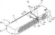
Fig. 1 is the three-dimensional exploded view of the utility model NGFF connector construction.
Fig. 2 is the three-dimensional combination figure of the utility model NGFF connector construction.
Fig. 3 is the generalized section of the utility model NGFF connector construction.
Fig. 4 is another generalized section of the utility model NGFF connector construction.
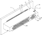
Fig. 5 is the three-dimensional exploded view of the utility model NGFF connector construction and circuit board.
Fig. 6 is the three-dimensional combination figure of the utility model NGFF connector construction and circuit board.
Fig. 7 is the assembled sectional view of the utility model NGFF connector construction and circuit board.
Fig. 8 is the use view of the utility model NGFF connector construction.
Fig. 9 is another use view of the utility model NGFF connector construction.
Figure 10 is the use view of the utility model NGFF connector assembly.
In figure, 10 ... NGFF connector assembly
20 ... NGFF connector construction
1 ... circuit board
11 ... location hole
12 ... fixing hole
13 ... terminal connection part
2 ... NGFF specification socket
21 ... insulating body
22 ... first surface
221 ... inserting groove
222 ... the first inwall
223 ... the second inwall
23 ... second
231 ... angle
232 ... upright fixed leg
233 ... four jiaos of coupling ends
234 ... the first ora terminalis
235 ... the second ora terminalis
24 ... the first terminal
241 ... the first contact site
242 ... the first docking section
243 ... the one V font section
244 ... the one L font section
25 ... the second terminal
251 ... the second contact site
252 ... the second docking section
253 ... the 2nd V font section
254 ... the 2nd L font section
100 ... SSD card
D ... notch direction
S ... surface.
Embodiment
Below in conjunction with the drawings and specific embodiments, the utility model is described in further detail, so that those skilled in the art can better understand the utility model being implemented, but illustrated embodiment is not as to restriction of the present utility model.
Please refer to shown in Fig. 1 to Figure 10, the utility model provides a kind of NGFF connector assembly and structure thereof, and this NGFF connector assembly 10 mainly comprises that M.2 a circuit board 1 and a plurality of NGFF(claim again) specification socket 2; NGFF connector construction 20 comprises that M.2 a NGFF(claims again) specification socket 2.
As shown in Figures 5 to 9, this circuit board 1 is for NGFF connector construction 20, circuit board 1 has a pair of location hole 11, a pair of fixing hole 12 and 13, two location holes 11 of a plurality of terminal connection part and two fixing holes 12 and is configured in the both sides of each group terminal connection part 13.
As shown in Figures 1 to 9, the utility model NGFF connector construction 20, M.2 this NGFF(claims again) quantity of specification socket 2 is one, M.2 NGFF(claims again) specification socket 2 has an insulating body 21, insulating body 21 has a relative first surface 22 and one second 23, first surface 22 is provided with an inserting groove 221, second 23 corresponding circuits plate 1 connects, to make NGFF(claim again M.2) specification socket 2 is installed on circuit board 1, and the notch direction d of each inserting groove 221 and the surperficial s of circuit board 1 are arranged perpendicular.
Further illustrate as follows, second 23 have towards away from first surface 22 directions extend a pair of angle 231, pair of upright fixed leg 232, this plugs the corresponding each location hole 11 of angle 231, this plugs the corresponding each fixing hole 12 of upright fixed leg 232.
Wherein, second 23 has four jiaos of coupling ends 233, and this is disposed on four jiaos of coupling ends 233 with diagonal way respectively upright fixed leg 232 angle 231 and this.
Moreover, in inserting groove 221, have one first relative inwall 222 and one second inwall 223, M.2 NGFF(claims again) specification socket 2 has a plurality of the first terminals 24 that configure along the first inwall 222 and a plurality of the second terminals 25 that configure along the second inwall 223.
Be described in detail as follows, one end of each the first terminal 24 has one first contact site 241, and the other end has one first docking section 242; Each second terminal 25 one end has one second contact site 251, and the other end has one second docking section 252.
Wherein, each the first contact site 241 and each the second contact site 251 are formed in inserting groove 221 also opposite each other, each first contact site 241 has one the one V font section 243 bending towards the second contact site 251, and each second contact site 251 has one the 2nd V font section 253 bending towards the first contact site 241.
Again, each the first docking section 242 and each the second docking section 252 are exposed to second 23, each second 23 both sides has one first ora terminalis 234 of parallel and contiguous the first inwall 222 and one second ora terminalis 235 of parallel and contiguous the second inwall 223, each first docking section 242 has one the one L font section 244 bending towards the first ora terminalis 234, each second docking section 252 has one the 2nd L font section 254 bending towards the second ora terminalis 235, and each L font section 244 and corresponding each terminal connection part 12 welderings of each the 2nd L font section 254 are established.
In addition, inserting groove 221 is for to offer the groove to second 23 from first surface 22, but not as restriction, its visual actual conditions are adjusted voluntarily.Therefore, inserting groove 221 also can be from first surface 22 and offers a groove of offering to inside.
As shown in Figure 5 to Figure 6, the utility model is the combination of connector construction 20 M.2, it utilizes NGFF(to claim again M.2) specification socket 2, there is insulating body 21, insulating body 21 has relative first surface 22 and second 23, and first surface 22 is provided with 221, the second 23 corresponding circuits plates 1 of inserting groove and connects, to make NGFF(claim again M.2) specification socket 2 is installed on circuit board 1, and the notch direction d of inserting groove 221 and the surperficial s of circuit board 1 are arranged perpendicular.With this, the notch direction d of inserting groove 221 and the surperficial s of circuit board 1 are arranged perpendicular, make M.2 connector 2 circuit board 1 around have the more long-pending energy of multiaspect supplied for electronic part installation, to reach the service efficiency that promotes circuit board 1.
As shown in Figures 5 to 9, the use state of the utility model NGFF connector construction 20, first, as shown in figure five to figure seven, this plugs the corresponding each location hole 11 of angle 231, this plugs the corresponding each fixing hole 12 of upright fixed leg 232, and each the first docking section 242 and each the second docking section 252 are exposed to second 23 and 12 welderings of corresponding each terminal connection part are established, and M.2 NGFF(is claimed again) specification socket 2 is installed on circuit board 1; In addition, as shown in Fig. 8 to Fig. 9, the corresponding inserting groove 221 of SSD card 100 plugs and is electrically connected, because the notch direction d of inserting groove 221 and the surperficial s of circuit board 1 are arranged perpendicular, make SSD card 100 also be arranged perpendicular with the surperficial s of circuit board 1, so M.2 NGFF(claims again) specification socket 2 circuit board 1 around need not reserve area and be installed with to SSD card 100, and then circuit board 1 can mounting electronic parts area change, to promote the service efficiency of circuit board.
In addition, there are four jiaos of coupling ends 233 for second 23, this is disposed on four jiaos of coupling ends 233 with diagonal way respectively upright fixed leg 232 angle 231 and this, M.2 NGFF(is claimed again) specification socket 2 can firmly be installed on circuit board 1 by four jiaos of coupling ends 233, and then the binding ability of reinforcement NGFF connector construction 20 and circuit board 1.
Moreover, each first docking section 242 has the L font section 244 bending towards the first ora terminalis 234, each second docking section 252 has the 2nd L font section 254 bending towards the second ora terminalis 235, each L font section 244 and corresponding each terminal connection part 12 welderings of each the 2nd L font section 254 are established, to allow NGFF(claim again M.2) specification socket 2 establishes more convenient convenience with the weldering of circuit board 1, and the moulding of a L font section 244 and each the 2nd L font section 254 can stably be supported NGFF(and be claimed again M.2) weight of specification socket 2, and then the structural strength of lifting NGFF connector construction 20.
As shown in figure 10, the utility model NGFF connector assembly 10, this NGFF connector assembly 10 comprises a circuit board 1 and a plurality ofly claims again M.2 as the NGFF(of Fig. 1 to Fig. 9) specification socket 2.
The combination of the utility model NGFF connector assembly 10, it utilizes each NGFF(to claim again M.2) specification socket 2 has insulating body 21, insulating body 21 has relative first surface 22 and second 23, first surface 22 is provided with inserting groove 221, second 23 corresponding circuits plate 1 connects, to make each NGFF(claim again M.2) specification socket 2 is installed on circuit board 1 with arrangement mode arranged side by side, and the notch direction d of each inserting groove 221 and the surperficial s of circuit board 1 are arranged perpendicular.Wherein, M.2 each NGFF(claims again) specification socket 2 with longitudinal side by side mode or laterally side by side mode be arranged in circuit board 1.
With this, the notch direction d of each inserting groove 221 and the surperficial s of circuit board 1 are arranged perpendicular, so M.2 each NGFF(claims again) specification socket 2 is in longitudinal side by side mode or when laterally mode is arranged in circuit board 1 side by side, because M.2 NGFF(claims again) specification socket 2 circuit board 1 around need not reserve area and be installed with to SSD card 100, and M.2 each SSD card 100 claims again with each NGFF() the required space of grafting of specification socket 2 can not overlap each other, certainly also can not influence each other, M.2 each NGFF(is claimed again) specification socket 2 can select used alone or together, to reach the service efficiency that promotes NGFF connector assembly 10.
The above embodiment is only the preferred embodiment for absolutely proving that the utility model is lifted, and protection range of the present utility model is not limited to this.What those skilled in the art did on the utility model basis is equal to alternative or conversion, all within protection range of the present utility model.Protection range of the present utility model is as the criterion with claims.
Claims (17)
1. a NGFF connector construction, for a circuit board, is characterized in that, this NGFF connector construction comprises:
One NGFF specification socket, there is an insulating body, this insulating body has a relative first surface and one second, this first surface is provided with an inserting groove, the described circuit board of this second correspondence connects, to make this NGFF specification socket be installed on described circuit board, and the notch direction of this inserting groove and the surface of described circuit board are arranged perpendicular.
2. NGFF connector construction as claimed in claim 1, is characterized in that, wherein said circuit board has a pair of location hole, and this second mask has towards a pair of angle extending away from this first surface direction, and corresponding a pair of this location hole of a pair of this angle plugs.
3. NGFF connector construction as claimed in claim 2, it is characterized in that, wherein said circuit board has a pair of fixing hole, and this second mask has towards the pair of upright fixed leg extending away from this first surface direction, and the corresponding a pair of described fixing hole of a pair of this upright fixed leg plugs.
4. NGFF connector construction as claimed in claim 3, is characterized in that, wherein this second mask has four jiaos of coupling ends, and a pair of this angle and a pair of this upright fixed leg are disposed at this four jiaos of coupling ends with diagonal way respectively.
5. NGFF connector construction as claimed in claim 1, it is characterized in that, wherein in this inserting groove, have one first relative inwall and one second inwall, this NGFF specification socket has along a plurality of the first terminals of this first inner wall arrangement and along a plurality of second terminals of this second inner wall arrangement.
6. NGFF connector construction as claimed in claim 5, it is characterized in that, wherein each this first terminal one end has one first contact site, each this second terminal one end has one second contact site, respectively this first contact site and respectively this second contact site be formed in this inserting groove and be opposite each other, each this first contact site has towards one the one V font section of this second contact site bending, and each this second contact site has towards one the 2nd V font section of this first contact site bending.
7. NGFF connector construction as claimed in claim 5, it is characterized in that, wherein said circuit board has a plurality of terminal connection parts, each this first terminal other end has one first docking section, each this second terminal other end has one second docking section, respectively this first docking section and respectively this second docking section be exposed to this second, these second both sides has one first ora terminalis of parallel and contiguous this first inwall and one second ora terminalis of parallel and contiguous this second inwall, each this first docking section has towards one the one L font section of this first ora terminalis bending, each this second docking section has towards one the 2nd L font section of this second ora terminalis bending, respectively a L font section and respectively the corresponding described terminal connection part weldering of the 2nd L font section establish.
8. NGFF connector construction as claimed in claim 1, is characterized in that, wherein this inserting groove is offered to this second from this first surface.
9. a NGFF connector assembly, comprising:
One circuit board; And
A plurality of NGFF specification sockets, each this NGFF specification socket has an insulating body, this insulating body has a relative first surface and one second, this first surface is provided with an inserting groove, this is second in the face of should circuit board connecting, with order respectively this NGFF specification socket be installed on this circuit board with arrangement mode arranged side by side, and the notch direction of each this inserting groove and the surface of this circuit board are arranged perpendicular.
10. NGFF connector assembly as claimed in claim 9, it is characterized in that, the plural number that wherein this circuit board has arrangement arranged side by side is to location hole, and each this second mask has towards a pair of angle extending away from this first surface direction, respectively this to angle correspondence, respectively this plugs location hole.
11. NGFF connector assemblies as claimed in claim 10, it is characterized in that, the plural number that wherein this circuit board has arrangement arranged side by side is to fixing hole, and each this second mask has towards the pair of upright fixed leg extending away from this first surface direction, respectively this to upright fixed leg correspondence, respectively this plugs fixing hole.
12. NGFF connector assemblies as claimed in claim 11, is characterized in that, wherein each this second mask has four jiaos of coupling ends, and a pair of this angle and a pair of this upright fixed leg are disposed at this four jiaos of coupling ends with diagonal way respectively.
13. NGFF connector assemblies as claimed in claim 9, it is characterized in that, wherein in each this inserting groove, have one first relative inwall and one second inwall, each this NGFF specification socket has along a plurality of the first terminals of this first inner wall arrangement and along a plurality of second terminals of this second inner wall arrangement.
14. NGFF connector assemblies as claimed in claim 13, it is characterized in that, wherein each this first terminal one end has one first contact site, each this second terminal one end has one second contact site, respectively this first contact site and respectively this second contact site be formed in this inserting groove and be opposite each other, each this first contact site has towards one the one V font section of this second contact site bending, and each this second contact site has towards one the 2nd V font section of this first contact site bending.
15. NGFF connector assemblies as claimed in claim 13, it is characterized in that, wherein this circuit board has the plural groups terminal connection part of arrangement arranged side by side, each this first terminal other end has one first docking section, each this second terminal other end has one second docking section, respectively this first docking section and respectively this second docking section be exposed to this second, each these second both sides has one first ora terminalis of parallel and contiguous this first inwall and one second ora terminalis of parallel and contiguous this second inwall, each this first docking section has towards one the one L font section of this first ora terminalis bending, each this second docking section has towards one the 2nd L font section of this second ora terminalis bending, respectively a L font section and respectively the 2nd L font section correspondence respectively the weldering of this terminal connection part establish.
16. NGFF connector assemblies as claimed in claim 9, is characterized in that, wherein each this inserting groove is offered to this second from this first surface.
17. NGFF connector assemblies as claimed in claim 9, is characterized in that, wherein respectively this NGFF specification socket is arranged in this circuit board with mode longitudinally arranged side by side or mode laterally arranged side by side.
Priority Applications (1)
| Application Number | Priority Date | Filing Date | Title |
|---|---|---|---|
| CN201420039606.1U CN203690574U (en) | 2014-01-22 | 2014-01-22 | NGFF (Next Generation Form Factor) connector assembly and NGFF connector structure |
Applications Claiming Priority (1)
| Application Number | Priority Date | Filing Date | Title |
|---|---|---|---|
| CN201420039606.1U CN203690574U (en) | 2014-01-22 | 2014-01-22 | NGFF (Next Generation Form Factor) connector assembly and NGFF connector structure |
Publications (1)
| Publication Number | Publication Date |
|---|---|
| CN203690574U true CN203690574U (en) | 2014-07-02 |
Family
ID=51012443
Family Applications (1)
| Application Number | Title | Priority Date | Filing Date |
|---|---|---|---|
| CN201420039606.1U Expired - Lifetime CN203690574U (en) | 2014-01-22 | 2014-01-22 | NGFF (Next Generation Form Factor) connector assembly and NGFF connector structure |
Country Status (1)
| Country | Link |
|---|---|
| CN (1) | CN203690574U (en) |
Cited By (3)
| Publication number | Priority date | Publication date | Assignee | Title |
|---|---|---|---|---|
| TWI594108B (en) * | 2016-06-30 | 2017-08-01 | 廣達電腦股份有限公司 | Raiser card and method for supporting an apparatus with two interfaces |
| US10095648B2 (en) | 2016-04-04 | 2018-10-09 | Hewlett-Packard Development Company, L.P. | Cantilevered network interface card assembly having port connector accessible from region outside of computing device |
| US10483673B2 (en) | 2015-01-28 | 2019-11-19 | Hewlett-Packard Development Company, L.P. | Interposer device |
-
2014
- 2014-01-22 CN CN201420039606.1U patent/CN203690574U/en not_active Expired - Lifetime
Cited By (4)
| Publication number | Priority date | Publication date | Assignee | Title |
|---|---|---|---|---|
| US10483673B2 (en) | 2015-01-28 | 2019-11-19 | Hewlett-Packard Development Company, L.P. | Interposer device |
| US10095648B2 (en) | 2016-04-04 | 2018-10-09 | Hewlett-Packard Development Company, L.P. | Cantilevered network interface card assembly having port connector accessible from region outside of computing device |
| TWI594108B (en) * | 2016-06-30 | 2017-08-01 | 廣達電腦股份有限公司 | Raiser card and method for supporting an apparatus with two interfaces |
| US10289588B2 (en) | 2016-06-30 | 2019-05-14 | Quanta Computer Inc. | Riser card |
Similar Documents
| Publication | Publication Date | Title |
|---|---|---|
| CN102315532B (en) | Electric connector | |
| CN103825122B (en) | Power connector | |
| JP6081236B2 (en) | Connector with guide | |
| CN203690574U (en) | NGFF (Next Generation Form Factor) connector assembly and NGFF connector structure | |
| WO2015165416A1 (en) | Usb plug capable of being plugged in positive and negative directions | |
| CN203760722U (en) | Electric connector | |
| CN201285809Y (en) | Electric connector, docking electric connector and combination thereof | |
| TWM479541U (en) | M.2 connector assembly and structure thereof | |
| CN102684020A (en) | Electric connector and butt joint electric connector thereof | |
| CN102544872A (en) | Power connector | |
| CN202917676U (en) | Power connector | |
| CN205122861U (en) | USB connector and mobile terminal | |
| CN102201252A (en) | Connection structure of storage device | |
| JP3198372U (en) | Electrical connector | |
| CN105375177A (en) | USB 3.1 type plug connector | |
| CN202259844U (en) | Micro universal serial bus (USB) 3.0 connector | |
| CN102201251B (en) | Storage apparatus connection structure and composite connector thereof | |
| CN201515033U (en) | Connecting structure of hollow inner conductor cable | |
| CN201576801U (en) | Electric connector | |
| CN203134996U (en) | Multi-cable electric coupler | |
| CN202888460U (en) | Plug | |
| CN201336485Y (en) | Matrix socket and matrix electric connector | |
| CN203721980U (en) | Rapid connector assembly with magnetic-controlled bending probes | |
| CN203277835U (en) | Wire-to-plate electric connector | |
| CN203850469U (en) | Rectangular printed circuit connector |
Legal Events
| Date | Code | Title | Description |
|---|---|---|---|
| C14 | Grant of patent or utility model | ||
| GR01 | Patent grant | ||
| CX01 | Expiry of patent term | ||
| CX01 | Expiry of patent term |
Granted publication date: 20140702 |