CN203686661U - Light source - Google Patents
Light source Download PDFInfo
- Publication number
- CN203686661U CN203686661U CN201320868312.5U CN201320868312U CN203686661U CN 203686661 U CN203686661 U CN 203686661U CN 201320868312 U CN201320868312 U CN 201320868312U CN 203686661 U CN203686661 U CN 203686661U
- Authority
- CN
- China
- Prior art keywords
- light
- reflection part
- reflecting surface
- lens
- light source
- Prior art date
- Legal status (The legal status is an assumption and is not a legal conclusion. Google has not performed a legal analysis and makes no representation as to the accuracy of the status listed.)
- Expired - Fee Related
Links
Images


Abstract
The utility model relates to a light source. The light source comprises an LED (light emitting diode), a lens and a reflecting part, wherein the reflecting part comprises a reflecting surface; the light of the LED is emitted to the reflecting part after being subjected to light distribution by the lens, and then is emitted to a predetermined direction after being reflected by the reflecting surface of the reflecting part. Compared with the prior art, the light source provided by the utility model has the advantages that the light ray can be emitted to the predetermined direction in a controllable mode, and the lighting effect is higher.
Description
Technical field
The utility model relates to lighting field, relates in particular to a kind of light source.
Background technology
The light of LED is lambert's shape and distributes, very strong at low-angle direction light, wide-angle direction light a little less than, if do not used control optical element, its light can not be controllably to predetermined direction transmitting, can not meet specific lighting demand.Therefore,, in order to make light to predetermined direction outgoing, control optical element is absolutely necessary.For example, in order to strengthen the light intensity of wide-angle direction, some manufacturers are by the following technical solutions: make light guide member with transparent material, one end of this light guide member is provided with incidence surface, its other end is provided with reflecting surface, the light of LED is irradiated to reflecting surface from incidence surface enters light guide member again, after reflecting surface reflection from the side outgoing of light guide member.Although this technology can make the light of LED launch to predetermined direction, the part light of LED can be between the reflecting surface of light guide member, side and incidence surface Circulated reflection, consume in light guide member, cause the reduction of light efficiency.
Utility model content
Technical problem to be solved in the utility model is to provide a kind of light source.
In order to solve above technical problem, light source of the present utility model comprises LED, lens and reflection part, and described reflection part comprises reflecting surface; The light of described LED reflection part described in directive after described lens luminous intensity distribution, then through the backward predetermined direction outgoing of reflecting surface reflection of described reflection part.
Preferably, the reflecting surface of described reflection part is diffuse surface.
Preferably, the reflecting surface of described reflection part is relative with the exiting surface of described lens.
Preferably, the reflecting surface of described reflection part is towards the proceeds posterolateral of described LED.
Preferably, the reflecting surface of described reflection part is the reflecting surface that makes the reflecting part transmission of light part, and the part light that is irradiated to the LED of described reflecting surface passes described reflection part outgoing.
Preferably, the reflecting surface of described reflection part is made the coating of part light transmissive portion light reflection and is formed by the surface setting at described reflection part.
Preferably, the reflecting surface of described reflection part is provided with protuberance or recess.
Preferably, described reflection part and described lens are two independently parts.
Preferably, the reflecting surface of described reflection part is back taper.
Preferably, described LED, described lens and described reflection part are arranged in order along the optical axis direction of described LED.
Preferably, described lens are that condenser lens is so that the light of described LED converges to the reflecting surface of described reflection part.
Preferably, described lens are TIR lens or Fresnel Lenses.
Preferably, described reflection part flare.
Preferably, described lens-ring is around described reflection part.
Preferably, described lens be spreadlight lens so that the light of described LED to the reflecting surface deviation of described reflection part.
Preferably, the reflecting surface of described reflection part and the exiting surface of described lens are every Kongxiang pair.
Compare with prior art, the light of light source of the present utility model not only can be controllably to predetermined direction outgoing, and light efficiency is higher.
Brief description of the drawings
Fig. 1 is the cutaway view of a kind of embodiment of light source of the present utility model;
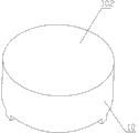
Fig. 2 is the schematic perspective view of reflection part in Fig. 1;
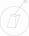
Fig. 3 is the enlarged drawing of the local A of reflection part in Fig. 2;
Fig. 4 is the schematic perspective view at a visual angle of lens in Fig. 1;
Fig. 5 is the schematic perspective view at another visual angle of lens in Fig. 4;
Fig. 6 is the light path schematic diagram of light source in Fig. 1;
Fig. 7 is the schematic perspective view at a visual angle of Fresnel Lenses;
Fig. 8 is the schematic perspective view at another visual angle of the Fresnel Lenses in Fig. 7;
Fig. 9 is the cutaway view of the another kind of embodiment of light source of the present utility model;
Figure 10 is the schematic perspective view at a visual angle of reflection part in Fig. 9;
Figure 11 is the schematic perspective view at another visual angle of reflection part in Fig. 9;
Figure 12 is the schematic perspective view at a visual angle of the lens in Fig. 9;
Figure 13 is the schematic perspective view at another visual angle of the lens in Fig. 9;
Figure 14 is the cutaway view of the lens in Fig. 9;
Figure 15 is the light path schematic diagram of light source in Fig. 9.
Detailed description of the invention
First it should be noted that, the utility model taking candle bubble lamp as example, steeps lamp but specific implementation form of the present utility model is not limited to candle in description process, also comprises the light sources such as bulb lamp.For the ease of the utility model is described, at this, orientation is defined: the direction of extending along the optical axis of LED or light source is the front of LED or light source, particularly, in Fig. 1, the direction straight up taking LED or light source as starting point is the front of LED or light source; The direction contrary with front is rear, and particularly, the direction straight down taking LED or light source as starting point in Fig. 1 is the rear of LED or light source; Direction taking LED or light source as the optical axis perpendicular to LED or light source of starting point is as side; Wei Ce front, region between aforesaid front and side; Region between aforesaid rear and side is proceeds posterolateral.
Embodiment 1:
Below in conjunction with Fig. 1 to Fig. 6, a kind of embodiment of the present utility model is elaborated.The light source of the present embodiment comprises LED 1, lens 2 and reflection part 3.Described reflection part 3 comprises reflecting surface 31; The light of described LED 1 reflection part 3 described in directive after described lens 2 luminous intensity distributions, then reflect backward predetermined direction outgoing through the reflecting surface 31 of described reflection part 3.Described light source also comprises lamp holder 9, lamp body 8 and cell-shell 7.Described LED 1, lens 2 and reflection part 3 are arranged in the space that described lamp body 8 and cell-shell 7 surround, and these parts can be installed in the mode of mechanical field routine, and these are all the common practise of this area, are not repeated herein.In this light source, described lens 2 and described reflection part 3 match, play the effect of directed control light, particularly, described lens 2 make the light of described LED 1 by reflection part 3 described in predetermined angle and light distribution directive, and reflection part 3 makes the light of its reflecting surface 31 of directive distribute to predetermined direction outgoing by predetermined angle and light.The concrete angle parameter of beam projecting and light distributed constant depend on the concrete structure of described lens 2 and described reflection part 3 and both relative position relations.That is to say, by changing the concrete structure of described lens 2 and described reflection part 3 and both relative position relations, the light of described LED 1 finally can be according to actual needs with different angles and light distribution outgoing.For example, in order to strengthen the light intensity of light source side and proceeds posterolateral, make in the present embodiment following design: described LED 1, described lens 2 and described reflection part 3 are arranged in order along the optical axis direction of described LED 1; Described lens 2 are for to make the light of described LED 1 converge to the TIR lens of described reflecting surface 31; The reflecting surface 31 of described reflection part 3 is back taper, and reflecting surface 31 is towards the proceeds posterolateral of LED 1 like this; Thereby make the side of light source described in the part light directive of LED 1, make the proceeds posterolateral of light source described in part light directive, strengthened the light intensity of this both direction, improve the light intensity of light source in wide-angle direction, meet specific lighting demand.Particularly, as depicted in figs. 1 and 2, described reflection part 3 entirety are back taper, and the side of its back taper is set to reflecting surface 31.As shown in Figure 1, Figure 4 and Figure 5, described lens 2 comprise the first incidence surface 22, the second incidence surface 21, reflecting surface 23, the first exiting surface 25 and the second exiting surface 26, the concrete structure of these lens 2 and light distribution characteristic are the common practise of this area, and its light distribution characteristic as shown in Figure 6, is not repeated herein.Compare with prior art, the light of light source of the present utility model not only can be controllably to predetermined direction outgoing; And because the light of LED 1 is from described lens 2 outgoing, do not need through light transmission mediums such as glass directly reflection part described in directive, fiber-loss is less, and light efficiency is higher.In the present embodiment, the reflecting surface 31 of described reflection part 3 is diffuse surface, like this, can make the beam projecting angle of light source larger, and light is also more even.The reflecting surface 31 of described reflection part 3 and the exiting surface 25 of described lens 2, exiting surface 26 are relative, like this, light is from described lens 2 outgoing, without through the material medium of described reflection part 3 and described in can direct irradiation on reflecting surface 31, avoid the fiber-loss of LED 1 in described reflection part 3, thereby further improved the light efficiency of light source.In the present embodiment, the reflecting surface 31 of described reflection part 3 is for making the reflecting surface of light part reflecting part transmission, the part light that is irradiated to the LED 1 of described reflecting surface 31 passes described reflection part 3 outgoing, like this, the light of LED 1 also can be irradiated in He Ce front, the front of LED 1, thereby makes the irradiating angle of light source become larger.The reflecting surface 31 of described reflection part 3 is made the coating of part light transmissive portion light reflection and is formed by the surface setting at described reflection part 3, particularly, the material of coating can be metal material, for example silver or aluminium, can control reflection of light rate and transmissivity by controlling the thickness of described coating.Reflectivity or the transmissivity of described reflection part 3 are selected according to actual needs, and in the present embodiment, reflectivity is 70%, and transmissivity is 30%.As shown in Figures 2 and 3, the reflecting surface 31 of described reflection part 3 is provided with recess 32, the quantity of described recess 32 is multiple, and each recess 32 spaces arrange, by recess 32 is set, change the local shape of reflecting surface 31, thereby broken the reflexive property of reflecting surface 32 at this regional area, form with the different reflecting effect in other regions at this regional area, intersperse decoration function thereby play.The local surfaces 321 of described recess 32 is towards the rear of described light source, thereby also can strengthen the light intensity of the proceeds posterolateral that is irradiated to this light source.Described reflection part 3 and described lens 2 are two independently parts.The reflecting surface 31 of described reflection part 3 and the exiting surface 25 of described lens 2 and exiting surface 26 are every Kongxiang pair, be not have solid-state light transmission medium between reflecting surface 31 and exiting surface 25 and exiting surface 26, can avoid light, in solid transparent medium, total reflection occurs and consume in solid transparent medium, thereby further improving light efficiency.Below in conjunction with Fig. 6, the light path of this light source is schematically described: the reflecting surface 31 of the light of LED 1 directive reflection part 3 after lens 2 luminous intensity distributions, after reflecting surface 31 reflections, form the light s of directive side and the light b of directive proceeds posterolateral, light f sees through reflection part 3 outgoing, distribute thereby form the light that irradiating angle is larger, met the lighting demand of wide-angle.
Compare with prior art, the light of light source of the present utility model not only can be controllably to predetermined direction outgoing, and light efficiency is higher.
As the simple deformation of the present embodiment, described lens also can adopt the Fresnel Lenses 10 shown in Fig. 7 to Fig. 8, these lens 10 comprise zigzag incidence surface 101 and exiting surface 102, and the concrete structure of these lens 10 and light distribution characteristic are the common practise of this area, are not repeated herein.
As the simple deformation of the present embodiment, protuberance also can be set on described reflecting surface, to have broken the reflexive property of reflecting surface at regional area, form with the different reflecting effect in other regions at this regional area, intersperse decoration function thereby play.
Embodiment 2:
Below in conjunction with Fig. 9 to Figure 15, another kind of embodiment of the present utility model is elaborated.The light source of the present embodiment comprises LED 11, lens 5 and reflection part 6, and described reflection part 6 comprises reflecting surface 61; The light of described LED 11 reflection part 6 described in directive after described lens 5 luminous intensity distributions, then reflect backward predetermined direction outgoing through the reflecting surface 61 of described reflection part 6.Described light source also comprises lamp holder 19, lamp body 18 and cell-shell 17.Described LED 11, lens 5 and reflection part 6 are arranged in the space that described lamp body 18 and cell-shell 17 surround, and these parts can be installed with the mounting means of mechanical field routine, and these are all the common practise of this area, are not repeated herein.In this light source, described lens 5 and described reflection part 6 match, play the effect of directed control light, particularly, described lens 5 make the light of described LED 11 by reflection part 6 described in predetermined angle and light distribution directive, and reflection part 6 makes the light of its reflecting surface 61 of directive distribute to predetermined direction outgoing by predetermined angle and light.The concrete angle parameter of beam projecting and light distributed constant depend on the concrete structure parameter of described lens 5 and described reflection part 6 and both relative position relations.That is to say, by changing the concrete structure parameter of described lens 5 and described reflection part 6 and both relative position relations, the light of described LED 11 finally can be according to actual needs with different angles and light distribution outgoing.For example, in order to strengthen the light intensity of light source side and proceeds posterolateral, make in the present embodiment following design: described reflection part 6 flares, the reflecting surface 61 of described reflection part 6 is towards the proceeds posterolateral of described LED11; Described lens 5 are around the root of described reflection part 6, described lens 5 be spreadlight lens so that the light of described LED11 to reflecting surface 61 deviations of described reflection part 6; Can strengthen like this intensity of the side of this light source and the light of proceeds posterolateral, thereby improve the light intensity of light source in wide-angle direction, meet specific lighting demand.Compare with prior art, the light of light source of the present utility model not only can be controllably to predetermined direction outgoing; And because the light of LED 11 is from described lens 5 outgoing, do not need through light transmission mediums such as glass directly reflection part 6 described in directive, fiber-loss is less, and light efficiency is higher.Particularly, as shown in Figure 10, Figure 11 and Figure 13, the surface relative with the exiting surface 57 of lens 5 of described reflection part 6 is reflecting surface 61, its another surface 62 is not reflecting surface, like this, light is from described lens 5 outgoing, without through the material medium of described reflection part 6 and described in can direct irradiation on reflecting surface 61, avoid the fiber-loss of LED 11 in described reflection part 6, thereby further improved the light efficiency of light source.As shown in Figure 12 to Figure 14, described lens 5 comprise the first incidence surface 51, the second incidence surface 52, the 3rd incidence surface 53, the first reflecting surface 55, the second reflecting surface 56 and exiting surface 57, the concrete structure of these lens 5 and light distribution characteristic are the common practise of this area, its light distribution characteristic as shown in figure 15, is not repeated herein.In the present embodiment, the reflecting surface 61 of described reflection part 6 is diffuse surface, like this, can make the beam projecting angle of light source larger, and light is also more even.In the present embodiment, the reflecting surface 61 of described reflection part 6 is for making the reflecting surface of light part reflecting part transmission, the part light that is irradiated to the LED 11 of described reflecting surface 61 passes described reflection part 6 outgoing, like this, the light of LED 11 also can be irradiated in He Ce front, the front of LED 11, thereby makes the irradiating angle of light source become larger.The reflecting surface 61 of described reflection part 6 is made the coating of part light transmissive portion light reflection and is formed by the surface setting at described reflection part 6, particularly, the material of coating can be metal material, for example silver or aluminium, can control reflection of light rate and transmissivity by controlling the thickness of described coating.Described reflection part 6 and described lens 5 are two independently parts.The reflecting surface 61 of described reflection part 6 and the exiting surface 57 of described lens 5 are every Kongxiang pair, be not have solid-state light transmission medium between reflecting surface 61 and exiting surface 57, can avoid light, in solid transparent medium, total reflection occurs and consume in solid transparent medium, thereby further improving light efficiency.The light path of the light source below in conjunction with Figure 15 to the present embodiment is done schematically to describe: the reflecting surface 61 of the light of LED 11 directive reflection part 6 after the deviation of lens 5, the side of part light s directive light source after reflecting surface 61 reflections, the proceeds posterolateral of part light b directive light source after reflecting surface 61 reflections, part light f is through front or the side front of reflection part 6 directive light sources.Distribute thereby form the light that irradiating angle is larger, met the lighting demand of wide-angle.
As the simple deformation of the present embodiment, described reflection part 6 and lens 5 also can be processed into one, and particularly, the root of described reflection part 6 connects with lens 5, and other structure and both position relationships remain unchanged.
As a kind of corrective measure of the present embodiment, also can protuberance or recess be set at the reflecting surface of reflection part 6 61, intersperse decoration function to play.
As described above, be only preferred embodiment of the present utility model, be not used for limiting practical range of the present utility model, all equalizations of doing according to the utility model change and modify, be all the utility model claim scope and contain, give an example no longer one by one here.
Claims (16)
1. a light source, is characterized in that, described light source comprises LED, lens and reflection part, and described reflection part comprises reflecting surface; The light of described LED reflection part described in directive after described lens luminous intensity distribution, then through the backward predetermined direction outgoing of reflecting surface reflection of described reflection part.
2. light source according to claim 1, is characterized in that, the reflecting surface of described reflection part is diffuse surface.
3. light source according to claim 1, is characterized in that, the reflecting surface of described reflection part is relative with the exiting surface of described lens.
4. light source according to claim 1, is characterized in that, the reflecting surface of described reflection part is towards the proceeds posterolateral of described LED.
5. light source according to claim 1, is characterized in that, the reflecting surface of described reflection part is the reflecting surface that makes the reflecting part transmission of light part, and the part light that is irradiated to the LED of described reflecting surface passes described reflection part outgoing.
6. light source according to claim 5, is characterized in that, the reflecting surface of described reflection part is made the coating of part light transmissive portion light reflection and formed by the surface setting at described reflection part.
7. light source according to claim 1, is characterized in that, the reflecting surface of described reflection part is provided with some protuberances or recess.
8. light source according to claim 1, is characterized in that, described reflection part and described lens are two independently parts.
9. according to the light source described in any one in claim 1 to 8, it is characterized in that, the reflecting surface of described reflection part is back taper.
10. light source according to claim 9, is characterized in that, described LED, described lens and described reflection part are arranged in order along the optical axis direction of described LED.
11. light sources according to claim 9, is characterized in that, described lens are that condenser lens is so that the light of described LED converges to the reflecting surface of described reflection part.
12. light sources according to claim 11, is characterized in that, described lens are TIR lens or Fresnel Lenses.
13. according to the light source described in any one in claim 1 to 8, it is characterized in that, described reflection part flare.
14. light sources according to claim 13, is characterized in that, described lens-ring is around described reflection part.
15. light sources according to claim 13, is characterized in that, described lens be spreadlight lens so that the light of described LED to the reflecting surface deviation of described reflection part.
16. light sources according to claim 1, is characterized in that, the reflecting surface of described reflection part and the exiting surface of described lens are every Kongxiang pair.
Priority Applications (1)
| Application Number | Priority Date | Filing Date | Title |
|---|---|---|---|
| CN201320868312.5U CN203686661U (en) | 2013-12-27 | 2013-12-27 | Light source |
Applications Claiming Priority (1)
| Application Number | Priority Date | Filing Date | Title |
|---|---|---|---|
| CN201320868312.5U CN203686661U (en) | 2013-12-27 | 2013-12-27 | Light source |
Publications (1)
| Publication Number | Publication Date |
|---|---|
| CN203686661U true CN203686661U (en) | 2014-07-02 |
Family
ID=51008558
Family Applications (1)
| Application Number | Title | Priority Date | Filing Date |
|---|---|---|---|
| CN201320868312.5U Expired - Fee Related CN203686661U (en) | 2013-12-27 | 2013-12-27 | Light source |
Country Status (1)
| Country | Link |
|---|---|
| CN (1) | CN203686661U (en) |
Cited By (1)
| Publication number | Priority date | Publication date | Assignee | Title |
|---|---|---|---|---|
| CN104747925A (en) * | 2013-12-27 | 2015-07-01 | 欧普照明股份有限公司 | Light source |
-
2013
- 2013-12-27 CN CN201320868312.5U patent/CN203686661U/en not_active Expired - Fee Related
Cited By (1)
| Publication number | Priority date | Publication date | Assignee | Title |
|---|---|---|---|---|
| CN104747925A (en) * | 2013-12-27 | 2015-07-01 | 欧普照明股份有限公司 | Light source |
Similar Documents
| Publication | Publication Date | Title |
|---|---|---|
| CN106247279B (en) | Lens and its light emitting device | |
| TW201344248A (en) | Lens and light source module | |
| WO2019109895A1 (en) | Reflective-type thick wall light guide and illumination apparatus | |
| US10627078B2 (en) | Method and system for producing a beam of illumination having smooth edges | |
| CN204879674U (en) | Stage lighting department all | |
| CN102748707A (en) | Floodlight total-reflection lens and LED (Light Emitting Diode) lamp using lens | |
| CN105736974A (en) | Light distribution lens and lighting device adopting same | |
| CN203731286U (en) | Led lens | |
| CN204062850U (en) | A kind of LED lens of extensive angle and there is the LED lamp of these lens | |
| US9366416B2 (en) | Lens and LED retrofit lamp | |
| CN109027968B (en) | Light emitting system | |
| CN205331882U (en) | Optical devices and lighting device | |
| CN203258494U (en) | Light-emitting device and relevant projection system | |
| CN205048201U (en) | Spreadlight lens and LED bar lamp | |
| CN203686661U (en) | Light source | |
| CN204717600U (en) | A kind of wide-angle luminous lens | |
| CN102947737A (en) | Illumination device with waveguide and LEDs | |
| CN203068203U (en) | Lighting lamp | |
| CN104747925A (en) | Light source | |
| CN204648006U (en) | A kind of LED optical system of adjustable focus | |
| CN105222086A (en) | Secondary optical element and light source module | |
| CN103994395A (en) | Led optical system and lamp | |
| CN208011622U (en) | A kind of optical module and lighting device | |
| CN204648118U (en) | A kind of reflective light conducting cylinder | |
| CN204648116U (en) | A kind of LED optical system |
Legal Events
| Date | Code | Title | Description |
|---|---|---|---|
| C14 | Grant of patent or utility model | ||
| GR01 | Patent grant | ||
| CF01 | Termination of patent right due to non-payment of annual fee |
Granted publication date: 20140702 Termination date: 20211227 |
|
| CF01 | Termination of patent right due to non-payment of annual fee |