CN203686579U - Liquid nitrogen pressure reducing device - Google Patents
Liquid nitrogen pressure reducing device Download PDFInfo
- Publication number
- CN203686579U CN203686579U CN201420035194.4U CN201420035194U CN203686579U CN 203686579 U CN203686579 U CN 203686579U CN 201420035194 U CN201420035194 U CN 201420035194U CN 203686579 U CN203686579 U CN 203686579U
- Authority
- CN
- China
- Prior art keywords
- liquid nitrogen
- valve
- pressure
- storage tank
- reducing device
- Prior art date
- Legal status (The legal status is an assumption and is not a legal conclusion. Google has not performed a legal analysis and makes no representation as to the accuracy of the status listed.)
- Expired - Fee Related
Links
Images
Landscapes
- Filling Or Discharging Of Gas Storage Vessels (AREA)
Abstract
The utility model discloses a liquid nitrogen pressure reducing device which comprises a liquid nitrogen storage tank, a liquid nitrogen inlet, an inlet stop valve, a liquid nitrogen outlet stop valve, a liquid nitrogen outlet pipe, a liquid nitrogen vaporizer, a liquid nitrogen recycling valve and a liquid nitrogen recycling pipeline. A safety valve is further installed in front of the liquid nitrogen recycling valve. According to the liquid nitrogen pressure reducing device, the problem of danger due to extremely high pressure generated by volatilization of liquid nitrogen in the liquid nitrogen storage tank is solved, when the pressure in the liquid nitrogen storage tank reaches an alarm position, automatic pressure reduction is started until a safe pressure value is achieved, nitrogen discharged due to pressure reduction is delivered to a use terminal through the pipeline so as to be fully used, safe production is guaranteed, and energy is saved.
Description
Technical field
The utility model relates to a kind of liquid nitrogen decompressor.
Background technique
Nitrogen is kind of a more stable gas, under general condition, can not react with material.Also be because this feature of nitrogen is widely used industrial.The storage of nitrogen is just important, because nitrogen is that gas is not easy to store, the GN 2 liquefaction need to be stored for liquid nitrogen.Extensively adopting at present liquid nitrogen storage tank to store liquid nitrogen, because liquid nitrogen can volatilize, after the pressure in liquid nitrogen storage tank reaches certain value, can cause danger, is clock potential safety hazard to producing.
Summary of the invention
Technical problem to be solved in the utility model is to provide a kind of decompressor of liquid nitrogen storage tank.
2, the technical solution of the utility model is: a kind of liquid nitrogen decompressor; comprise liquid nitrogen storage tank, liquid nitrogen import and inlet shutoff valve, liquid nitrogen fluid stop valve and liquid nitrogen drain pipe, liquid nitrogen vaporizer, liquid nitrogen recovery valve and liquid nitrogen recovery channel, described liquid nitrogen recovery valve front end is provided with a safety valve; The air pressure of described safety valve in liquid nitrogen storage tank higher than arrange highpressure value time open, during lower than barometric minimum value, close; Described liquid nitrogen recovery valve can manually openedly reduce pressure in the time that pressure is in the middle of maximum pressure and minimum pressure value; Described liquid nitrogen recovery channel uses terminal to be connected with nitrogen.
the beneficial effects of the utility model are
1, the utility model reduces pressure to the nitrogen pressure of liquid nitrogen volatilization in liquid nitrogen storage tank, has avoided that nitrogen pressure is too high causes production safety danger.
2, when the utility model reduces pressure, the nitrogen discharging is directly used on product, saved the energy.
Accompanying drawing explanation
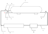
Fig. 1 is schematic diagram of the present utility model.
embodiment:
According to upper figure, the utility model is further illustrated:
A kind of liquid nitrogen decompressor, comprise liquid nitrogen storage tank 1, liquid nitrogen import 2 and inlet shutoff valve 3, liquid nitrogen fluid stop valve 4 and liquid nitrogen drain pipe 5, liquid nitrogen vaporizer 10, liquid nitrogen recovery valve 6 and liquid nitrogen recovery channel 7, described liquid nitrogen recovery valve 6 front ends are provided with a safety valve 8; The air pressure of described safety valve 8 in liquid nitrogen storage tank 1 higher than arrange highpressure value time open, during lower than barometric minimum value, close; Described liquid nitrogen recovery valve 6 can manually openedly reduce pressure in the time that pressure is in the middle of maximum pressure and minimum pressure value; Described liquid nitrogen recovery channel 7 uses terminal 9 to be connected with nitrogen.
Its working principle is as follows: the liquid nitrogen of subzero 198 degrees Celsius is inputted liquid nitrogen storage tank 1 from liquid nitrogen import 2, close inlet shutoff valve 3 when reaching warning position, when use, open liquid nitrogen fluid stop valve 4, by liquid nitrogen drain pipe 5, by liquid nitrogen, through liquid nitrogen vaporizer, 10 vaporizations become nitrogen, are delivered to nitrogen and use terminal 9.But liquid nitrogen is a volatile gas of appearance, the too high meeting of air pressure that the liquid nitrogen volatilization in liquid nitrogen storage tank 1 produces causes potential safety hazard, even causes blast.
In the time that the air pressure in liquid nitrogen storage tank 1 reaches the CLV ceiling limit value (the present embodiment is take 8MPAa as example) of setting, safety valve 8 is opened and is forced decompression, and in the time that the air pressure in liquid nitrogen storage tank 1 reaches the lower limit (the present embodiment is take 3MPAa as example) of setting, safety valve 8 cuts out.Air pressure in liquid nitrogen storage tank 1 is in the time of 3MPa-8MPa, and safety valve 8, in normal working, can carry out hand reducing pressure by recovery valve 6.The nitrogen that decompression is got rid of is transported to and is used terminal 9 by nitrogen recycling passage 7, avoids causing the waste of the energy.
Claims (4)
1. a liquid nitrogen decompressor, it is characterized in that, comprise liquid nitrogen storage tank, liquid nitrogen import and inlet shutoff valve, liquid nitrogen fluid stop valve and liquid nitrogen drain pipe, liquid nitrogen vaporizer, liquid nitrogen recovery valve and liquid nitrogen recovery channel, described liquid nitrogen recovery valve front end is also provided with a safety valve.
2. a kind of liquid nitrogen decompressor according to claim 1, is characterized in that, the air pressure of described safety valve in liquid nitrogen storage tank higher than arrange highpressure value time open, during lower than barometric minimum value, close.
3. a kind of liquid nitrogen decompressor according to claim 1, is characterized in that, described liquid nitrogen recovery valve can manually openedly reduce pressure in the time that pressure is in the middle of maximum pressure and minimum pressure value.
4. a kind of liquid nitrogen decompressor according to claim 1, is characterized in that, described liquid nitrogen recovery channel uses terminal to be connected with nitrogen.
Priority Applications (1)
| Application Number | Priority Date | Filing Date | Title |
|---|---|---|---|
| CN201420035194.4U CN203686579U (en) | 2014-01-21 | 2014-01-21 | Liquid nitrogen pressure reducing device |
Applications Claiming Priority (1)
| Application Number | Priority Date | Filing Date | Title |
|---|---|---|---|
| CN201420035194.4U CN203686579U (en) | 2014-01-21 | 2014-01-21 | Liquid nitrogen pressure reducing device |
Publications (1)
| Publication Number | Publication Date |
|---|---|
| CN203686579U true CN203686579U (en) | 2014-07-02 |
Family
ID=51008477
Family Applications (1)
| Application Number | Title | Priority Date | Filing Date |
|---|---|---|---|
| CN201420035194.4U Expired - Fee Related CN203686579U (en) | 2014-01-21 | 2014-01-21 | Liquid nitrogen pressure reducing device |
Country Status (1)
| Country | Link |
|---|---|
| CN (1) | CN203686579U (en) |
Cited By (2)
| Publication number | Priority date | Publication date | Assignee | Title |
|---|---|---|---|---|
| CN105526500A (en) * | 2016-01-08 | 2016-04-27 | 上海启元空分技术发展股份有限公司 | Liquid nitrogen recovering device and method |
| CN110109032A (en) * | 2019-05-06 | 2019-08-09 | 中国科学院上海微系统与信息技术研究所 | A kind of superconduction boat magnetism pressure stable-pressure device and air pressure method for stabilizing voltage |
-
2014
- 2014-01-21 CN CN201420035194.4U patent/CN203686579U/en not_active Expired - Fee Related
Cited By (3)
| Publication number | Priority date | Publication date | Assignee | Title |
|---|---|---|---|---|
| CN105526500A (en) * | 2016-01-08 | 2016-04-27 | 上海启元空分技术发展股份有限公司 | Liquid nitrogen recovering device and method |
| CN110109032A (en) * | 2019-05-06 | 2019-08-09 | 中国科学院上海微系统与信息技术研究所 | A kind of superconduction boat magnetism pressure stable-pressure device and air pressure method for stabilizing voltage |
| CN110109032B (en) * | 2019-05-06 | 2021-08-20 | 中国科学院上海微系统与信息技术研究所 | Superconducting aeromagnetic air pressure stabilizing device and air pressure stabilizing method |
Similar Documents
| Publication | Publication Date | Title |
|---|---|---|
| CN203925455U (en) | Voltage regulating type high voltage source-free mining-injecting gas wellhead chemicals-feeder | |
| CN203686579U (en) | Liquid nitrogen pressure reducing device | |
| WO2016073454A3 (en) | Compressed gad filling method and system | |
| CN105299443A (en) | Liquefied gas filling and replacement method | |
| CN204776898U (en) | Clear stifled device of thermal power factory high pressure air water coal bunker | |
| CN205026397U (en) | Take liquefied natural gas supercharging device of plunger pump | |
| CN204420567U (en) | Gasification system oxygen pipeline purges and uses high pressure nitrogen system | |
| CN205155542U (en) | Modified torch gas divides fluid reservoir to press liquid system | |
| CN205278765U (en) | Liquid ammonia fills device of dress | |
| CN204005247U (en) | Improved instrument air process system | |
| CN204153461U (en) | Supercharging speed-raising type CO 2tank car discharge system | |
| CN204372535U (en) | A kind of metal hydride hydrogen storage unit hydrogen self-filling system | |
| CN202252854U (en) | Natural gas filling alcohol atomization device | |
| CN202834751U (en) | Steel cylinder vacuum pumping device | |
| CN203010205U (en) | Air supply system used for benzene hydrogenation unit | |
| CN204005229U (en) | A kind of argon gas reclaims and fills bottle apparatus | |
| CN204273211U (en) | A kind of pneumatic perfuming device | |
| CN103867895A (en) | Gas supply system for benzene hydrogenation device | |
| CN204358198U (en) | A kind of low-pressure gas Safety relief valve | |
| CN204151310U (en) | Synthetic ammonia producer gas generator blowing out quick pressure relief device | |
| CN204328463U (en) | A kind of LNG Liquefied natural gas is unloaded regulator | |
| CN204328480U (en) | A kind of liquid gas stable-pressure device | |
| CN203516251U (en) | Double-direction balance valve device | |
| CN204017229U (en) | A kind of Puffer-type liquid extinguisher tank car | |
| CN204042432U (en) | With the liquid circuit module control box of proportioning device |
Legal Events
| Date | Code | Title | Description |
|---|---|---|---|
| C14 | Grant of patent or utility model | ||
| GR01 | Patent grant | ||
| TR01 | Transfer of patent right | ||
| TR01 | Transfer of patent right |
Effective date of registration: 20191025 Address after: No.118, Kangbao Road, ganyao Town, Jiashan County, Jiaxing City, Zhejiang Province Patentee after: Jiaxing Jun Hong Auto Parts Co., Ltd. Address before: Hangzhou City, Zhejiang province Yuhang District 311121 Futailu Thailand Street No. 23 Patentee before: Hangzhou Yunteng Air Conditioning & Radiator Parts Manufacturing Co., Ltd. |
|
| CF01 | Termination of patent right due to non-payment of annual fee | ||
| CF01 | Termination of patent right due to non-payment of annual fee |
Granted publication date: 20140702 Termination date: 20200121 |