CN203686543U - Lubricating oil tank for spinning - Google Patents
Lubricating oil tank for spinning Download PDFInfo
- Publication number
- CN203686543U CN203686543U CN201320784997.5U CN201320784997U CN203686543U CN 203686543 U CN203686543 U CN 203686543U CN 201320784997 U CN201320784997 U CN 201320784997U CN 203686543 U CN203686543 U CN 203686543U
- Authority
- CN
- China
- Prior art keywords
- oil
- oil outlet
- oil tank
- lubricating oil
- box body
- Prior art date
- Legal status (The legal status is an assumption and is not a legal conclusion. Google has not performed a legal analysis and makes no representation as to the accuracy of the status listed.)
- Expired - Fee Related
Links
Images
Abstract
The utility model discloses a lubricating oil tank for spinning, which comprises a box body, and is characterized in that the upper end of the box body is connected with an oil tank cover; the upper part of the oil tank cover is provided with an oil inlet; the oil inlet adopts a conic cylindrical structure of which the upper part is larger and the lower part is smaller; a top cap is screwed to the oil inlet; an oil outlet is formed in the side wall of the box body; a valve is arranged on the oil outlet. The conic cylindrical oil inlet of which the upper part is larger and the lower part is smaller is formed in the upper part of the oil tank cover to be convenient for lubricating oil to pour into, the oil tank is sealed by the top cap to prevent pollution, the valve arranged on the oil outlet can adjust the lubricating oil to be poured into, an oil outlet nozzle at one end pat of an oil outlet pipe can be more convenient for lubricating oil to pour out, a circle of sealant in the oil tank cover enables the sealing performance of the oil tank to be better, a bayonet at the upper end of the side wall of the box body enables the oil outlet pipe to be fixed when the oil outlet pipe is not in use, and square tempered glass embedded in one side wall of the box body can monitor the quantity of lubricating oil in the oil tank in real time. The lubricating oil tank has the advantages of simple structure, convenience in use and the like.
Description
Technical field
The utility model relates to field of textile machinery, especially weaving Lubricating oil tank.
Background technique
Lubricant oil is to be used in all kinds machinery to reduce friction; the fluid lubricant of protection machinery and workpiece; main play the effects such as lubricated, cooling, antirust, clean, sealing and buffering; motor in the running, if some friction positions can not get suitable lubricating, will produce dry friction; facts have proved; the heat that dry friction produces is at short notice enough to make metal molten, causes the damage of parts even stuck, therefore must give good lubricating to the friction position in motor.At present, mostly on textile manufacturing machine, be all provided with the oil can of lubricating oil filling, conveniently textile manufacturing machine maintained, but oil can mouth is all less, inconvenient toward the interior lubricating oil filling of oil can, if there is no careful oiling, be easy to make lubricant oil to spread, not only cause lubricant oil waste, also destroyed working environment.
Summary of the invention
In order to overcome the problems referred to above, the utility model provides a kind of weaving Lubricating oil tank simple in structure, easy to use.
The technical solution of the utility model is to provide a kind of weaving Lubricating oil tank, it comprises casing, it is characterized in that: described casing upper end connects a fuel tank cap, described fuel tank cap top comprises filler opening, described filler opening is up big and down small cone barrel type structure, the top cover that also spins on described filler opening, is also provided with oil outlet on described wall box, comprise a valve on described oil outlet.
Preferably, described oil outlet end connects an oil outlet tube.
Preferably, the described oil outlet tube the other end also connects an oil outlet.
Preferably, described fuel tank cap inside is also provided with a circle sealer.
Preferably, described wall box upper end also comprises a bayonet socket for fixing oil outlet tube.
Preferably, on described casing one sidewall, be also embedded with a square toughened glass.
Weaving of the present utility model is provided with up big and down small cone barrel type filler opening on fuel tank cap top with Lubricating oil tank, conveniently pour lubricant oil into, and top cover is closed fuel tank, prevents from polluting; Be arranged on the number that the valve on oil outlet can regulate lubricant oil to pour out, the oil outlet of oil outlet tube end can more convenient lubricant oil pour out, one circle sealer of fuel tank cap inside makes fuel tank better tightness, the bayonet socket of wall box upper end makes oil outlet tube fix in the time not using, the square toughened glass embedding on casing one sidewall can real-time monitor lubricant oil in fuel tank number, the utlity model has the advantages such as simple in structure, easy to use.
Accompanying drawing explanation
Fig. 1 is the perspective view of Lubricating oil tank for the weaving of the utility model most preferred embodiment.
Embodiment
Below embodiment of the present utility model is described in further detail.
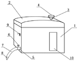
As shown in Figure 1; weaving Lubricating oil tank of the present utility model; it comprises casing 1; casing 1 upper end connects a fuel tank cap 2; fuel tank cap 2 tops comprise filler opening 3, and filler opening 3 is up big and down small cone barrel type structure, and a top cover 4 also spins on filler opening 3; on casing 1 sidewall, be also provided with oil outlet 5, on oil outlet 5, comprise a valve 6; Oil outlet 5 ends connect an oil outlet tube 7; Oil outlet tube 7 the other ends also connect an oil outlet 8, and fuel tank cap 2 inside are also provided with a circle sealer (not shown), and casing 1 sidewall upper also comprises a bayonet socket 9 for fixing oil outlet tube 7, is also embedded with a square toughened glass 10 on casing 1 one sidewalls.
In real work, open mailbox top cover, lubricant oil to be poured into from filler opening, lubricant oil enters in casing, opens the valve of oil outlet, and lubricant oil flows to oil outlet tube from oil outlet, is poured in oil can by the oil outlet of oil outlet tube one end, finishes the work; The not used time, snaps into oil outlet tube on bayonet socket, can also be how many by the oil mass in the toughened glass Real-Time Monitoring fuel tank of wall box.
Above embodiment is only the utility model a kind of mode of execution wherein, and it describes comparatively concrete and detailed, but can not therefore be interpreted as the restriction to the utility model the scope of the claims.It should be pointed out that for the person of ordinary skill of the art, without departing from the concept of the premise utility, can also make some distortion and improvement, these all belong to protection domain of the present utility model.Therefore, the protection domain of the utility model patent should be as the criterion with claims.
Claims (6)
1. a weaving Lubricating oil tank, it comprises casing, it is characterized in that: described casing upper end connects a fuel tank cap, described fuel tank cap top comprises filler opening, described filler opening is up big and down small cone barrel type structure, the top cover that also spins on described filler opening, is also provided with oil outlet on described wall box, comprise a valve on described oil outlet.
2. weaving Lubricating oil tank according to claim 1, is characterized in that: described oil outlet end connects an oil outlet tube.
3. weaving Lubricating oil tank according to claim 2, is characterized in that: the described oil outlet tube the other end also connects an oil outlet.
4. weaving Lubricating oil tank according to claim 3, is characterized in that: described fuel tank cap inside is also provided with a circle sealer.
5. weaving Lubricating oil tank according to claim 4, is characterized in that: described wall box upper end also comprises a bayonet socket for fixing oil outlet tube.
6. weaving Lubricating oil tank according to claim 5, is characterized in that: on described casing one sidewall, be also embedded with a square toughened glass.
Priority Applications (1)
| Application Number | Priority Date | Filing Date | Title |
|---|---|---|---|
| CN201320784997.5U CN203686543U (en) | 2013-12-04 | 2013-12-04 | Lubricating oil tank for spinning |
Applications Claiming Priority (1)
| Application Number | Priority Date | Filing Date | Title |
|---|---|---|---|
| CN201320784997.5U CN203686543U (en) | 2013-12-04 | 2013-12-04 | Lubricating oil tank for spinning |
Publications (1)
| Publication Number | Publication Date |
|---|---|
| CN203686543U true CN203686543U (en) | 2014-07-02 |
Family
ID=51008441
Family Applications (1)
| Application Number | Title | Priority Date | Filing Date |
|---|---|---|---|
| CN201320784997.5U Expired - Fee Related CN203686543U (en) | 2013-12-04 | 2013-12-04 | Lubricating oil tank for spinning |
Country Status (1)
| Country | Link |
|---|---|
| CN (1) | CN203686543U (en) |
Cited By (2)
| Publication number | Priority date | Publication date | Assignee | Title |
|---|---|---|---|---|
| CN103727375A (en) * | 2013-12-04 | 2014-04-16 | 吴江市大业丝绸整理有限公司 | Lubricating oil tank for spinning |
| CN108589082A (en) * | 2018-03-21 | 2018-09-28 | 吴江市佳格精密机械有限公司 | A kind of sewing machine gear assembly oiling device |
-
2013
- 2013-12-04 CN CN201320784997.5U patent/CN203686543U/en not_active Expired - Fee Related
Cited By (2)
| Publication number | Priority date | Publication date | Assignee | Title |
|---|---|---|---|---|
| CN103727375A (en) * | 2013-12-04 | 2014-04-16 | 吴江市大业丝绸整理有限公司 | Lubricating oil tank for spinning |
| CN108589082A (en) * | 2018-03-21 | 2018-09-28 | 吴江市佳格精密机械有限公司 | A kind of sewing machine gear assembly oiling device |
Similar Documents
| Publication | Publication Date | Title |
|---|---|---|
| CN203686543U (en) | Lubricating oil tank for spinning | |
| CN204828550U (en) | Drive arrangement's lubricated type gear | |
| CN211287833U (en) | Engine oil discharging equipment | |
| CN103727375A (en) | Lubricating oil tank for spinning | |
| CN102797887A (en) | Automatic tap water closing valve | |
| CN210896907U (en) | Transformer oil supplementing device | |
| CN203286249U (en) | Automatic oiling device | |
| CN208648722U (en) | Anti-dripping device is used in a kind of packing of honey | |
| CN203604965U (en) | Lubricating oil storage and taking device | |
| CN203258341U (en) | Bearing bush motor automatic oil recharging device | |
| CN205823582U (en) | Oil level controllers | |
| CN203488378U (en) | Oiling device for oil tank of roots blower | |
| CN217130936U (en) | Oil drain device of piston type air compressor | |
| CN110853884A (en) | Transformer oil supplementing device | |
| CN206261548U (en) | Easily device for cleaning glass | |
| CN203442096U (en) | Feed mixer truck reduction gearbox with observation device | |
| CN205852403U (en) | A kind of oil-air lubrication mechanism for Digit Control Machine Tool | |
| CN213954966U (en) | Oil discharge device for thin oil lubrication bearing box | |
| CN204568488U (en) | Gas discharging apparatus in a kind of oil groove of Oil & Gas Storage | |
| CN211952188U (en) | Oil injection device | |
| CN204005150U (en) | Self oil feeder | |
| CN202152876U (en) | Automatic tap water closing valve | |
| CN203892199U (en) | Special roots blower oil injection- heat dissipation device capable of preventing lubrication oil from splashing | |
| CN201890763U (en) | Oil sight glass | |
| CN201597909U (en) | Lubricating grease package container |
Legal Events
| Date | Code | Title | Description |
|---|---|---|---|
| C14 | Grant of patent or utility model | ||
| GR01 | Patent grant | ||
| CF01 | Termination of patent right due to non-payment of annual fee |
Granted publication date: 20140702 Termination date: 20141204 |
|
| EXPY | Termination of patent right or utility model |