CN203685462U - High-speed flow distribution cycloid hydraulic motor - Google Patents
High-speed flow distribution cycloid hydraulic motor Download PDFInfo
- Publication number
- CN203685462U CN203685462U CN201420012956.9U CN201420012956U CN203685462U CN 203685462 U CN203685462 U CN 203685462U CN 201420012956 U CN201420012956 U CN 201420012956U CN 203685462 U CN203685462 U CN 203685462U
- Authority
- CN
- China
- Prior art keywords
- hydraulic motor
- rotary shaft
- cycloid hydraulic
- needle bearing
- sealing
- Prior art date
- Legal status (The legal status is an assumption and is not a legal conclusion. Google has not performed a legal analysis and makes no representation as to the accuracy of the status listed.)
- Expired - Lifetime
Links
- 238000007789 sealing Methods 0.000 claims abstract description 34
- 239000007788 liquid Substances 0.000 claims abstract description 12
- 230000007246 mechanism Effects 0.000 claims abstract description 11
- 229910000831 Steel Inorganic materials 0.000 claims abstract description 8
- 238000010992 reflux Methods 0.000 claims abstract description 8
- 239000010959 steel Substances 0.000 claims abstract description 8
- 230000005540 biological transmission Effects 0.000 claims abstract description 6
- 125000006850 spacer group Chemical group 0.000 claims abstract description 6
- 238000009434 installation Methods 0.000 claims description 10
- 238000000034 method Methods 0.000 claims description 7
- 230000008569 process Effects 0.000 claims description 6
- 239000000463 material Substances 0.000 claims description 5
- 239000010720 hydraulic oil Substances 0.000 claims description 4
- 150000001875 compounds Chemical class 0.000 claims description 3
- 238000010438 heat treatment Methods 0.000 claims description 3
- 239000002131 composite material Substances 0.000 abstract 1
- 239000002184 metal Substances 0.000 description 8
- 230000006872 improvement Effects 0.000 description 4
- 230000008602 contraction Effects 0.000 description 3
- 239000003921 oil Substances 0.000 description 3
- 238000012856 packing Methods 0.000 description 3
- 102100029469 WD repeat and HMG-box DNA-binding protein 1 Human genes 0.000 description 2
- 101710097421 WD repeat and HMG-box DNA-binding protein 1 Proteins 0.000 description 2
- 238000006243 chemical reaction Methods 0.000 description 2
- 239000012530 fluid Substances 0.000 description 2
- 230000033001 locomotion Effects 0.000 description 2
- 230000015572 biosynthetic process Effects 0.000 description 1
- 238000010276 construction Methods 0.000 description 1
- 230000002596 correlated effect Effects 0.000 description 1
- 238000013461 design Methods 0.000 description 1
- 239000000428 dust Substances 0.000 description 1
- 238000005516 engineering process Methods 0.000 description 1
- 238000011835 investigation Methods 0.000 description 1
- 238000012546 transfer Methods 0.000 description 1
- 230000009466 transformation Effects 0.000 description 1
Images


Abstract
The utility model relates to a high-speed flow distribution cycloid hydraulic motor, belonging to the technical field of hydraulic transmission. The cycloid hydraulic motor comprises a shell with a liquid inlet and a reflux inlet; a rotor of a cycloid pin wheel pair and a composite hydraulic flow channel of a flow distribution supporting plate form a flow distribution mechanism; the shell has a step hole for directly mounting the outer circle of a rotary shaft seal; the length of a front bearing in the mounting direction of the rotary shaft seal is greater than that of a rear bearing; a spacer is mounted between the front and rear full needle bearings. The cycloid hydraulic motor adopting the L-shaped steel frame type rotary shaft seal sealing and multilayer sealing structure is simple in structure, easy to assemble and reliable to seal, unreliable sealing factors are removed, and the use cost is saved.
Description
Technical field
A kind of cycloidal pin wheels engagement pair that relates to the utility model realizes the cycloid hydraulic motor of hydraulic energy to mechanical energy conversion, and especially a kind of high-speed distributing cycloid hydraulic motor with non-linear thin plate complex liquid baric flow road, belongs to hydraulic transmission technology field.
Background technique
Cycloid hydraulic motor is conventional fluid pressure drive device, is also the conventional hydraulic pressure execution device of realizing hydraulic energy and convert to mechanical energy.Cycloid hydraulic motor has the advantages such as volume is little, specific power density is large, efficiency is high, speed range is wide, thereby is widely applied.
The basic structure of such device is on body shell or bonnet, to be shaped with liquid entering hole and refluxing opening, cycloidal pinion engaged pair and flow-distribution mechanism are equipped with in one end, flow-distribution mechanism can be placed on before or after cycloidal pinion engaged pair, be generally axle valve flow in front (body shell one side), be plane flow in rear (bonnet one side), the other end is equipped with output shaft.The rotor of cycloidal pinion engaged pair engages with the external gear of couple axle one end by internal spline, and the other end of couple axle is connected with output shaft transmission.When work, flow-distribution mechanism makes liquid entering hole engage chamber connection with the expansion of cycloidal pin wheel set, and the contraction chamber of cycloidal pin wheel set is communicated with refluxing opening.As a result, pressured fluid, from liquid entering hole enters body shell or bonnet, enters the expansion engagement chamber that cycloidal pinion engaged pair forms, and its volume is constantly expanded, and in the contraction engagement chamber that cycloidal pinion engaged pair forms simultaneously, liquid refluxes from refluxing opening; In this process, the rotor of cycloidal pinion engaged pair is expanded the pressure difference that engages chamber with contraction in engagement chamber and orders about rotation, and this is rotated by couple axle and is delivered to output shaft output, thereby realizes the conversion of hydraulic energy to mechanical energy.Meanwhile, flow-distribution mechanism is also by couple axle driven rotary, and the continuous switching connected state going round and beginning again, is continued transfer process.Like this, the output torque that motor just can be continuous, can say that cycloidal pinion engaged pair and flow-distribution mechanism are the cores of oil hydraulic motor.
According to the applicant understood, the runner design form of flow-distribution mechanism has multiple, is mainly divided into two kinds of flow modes of axle flow and plane flow, in hydraulic pressure handbook in early days, all has embodiment.Separately there is a kind of high-speed distributing cycloid hydraulic motor of similar plane distributing construction motor, flow system is relevant with rotor end-face duct, the thrust plate of motor is to integrate (as U.S. patent documents US4717320) with rotor, or at the extending end (as U.S. patent documents US3601513) of the couple axle coordinating with its internal spline, the former its shaft seal sealing assembling is comparatively complicated, correlated parts quantity is many, and it is many unreliable in use can to bring, and causes oil leakage phenomenon.
Summary of the invention
The purpose of this utility model is: the problem existing for above prior art, by the further investigation of the cycloid secondary motion mechanism to such motor, in application motor configuration to rotating seal ring require high, simple in structure and the reliable high-speed distributing cycloid hydraulic motor of a kind of rotating seal ring is proposed, thereby the movement output of the motor that can make is more steady, and performance is more stable.
The utility model is for above-mentioned model utility object, its technological scheme is: high-speed distributing cycloid hydraulic motor, comprise the housing that is shaped with liquid entering hole and refluxing opening, the cycloidal pin wheel set being made up of stator, rotor and pin tooth and the flow-distribution mechanism being made up of the complex liquid baric flow road of flow dunnage and the compound duct of rotor are equipped with in one end of described housing, and the delivery outlet of its other end is supported with the output shaft from stretching out in housing; The rotor of described cycloidal pin wheel set engages with the external gear of couple axle one end by internal spline, and the other end of described couple axle is connected with output shaft transmission; Its improvements are: described housing is shaped with the step hole that rotary shaft sealing is installed, described step hole is directly installed the cylindrical of rotary shaft sealing, described rotary shaft sealing is installed by housing bore the one end that completely fills needle bearing and is installed, the installation dimension that described former and later two completely fill needle bearing is consistent, front end props up to fully support and in dress needle bearing length, is greater than rear end and props up and fully support dress needle bearing, and described front and back completely fill spacer ring is installed between needle bearing.
The rotary shaft sealing sealing diameter of axle of described output shaft and front and back completely fill between the needle bearing installation diameter of axle thrust-bearing and end ring are installed, and described thrust-bearing is resisted against on the shaft shoulder of output shaft.
Above technological scheme is further improved: one end that described couple axle engages with rotor is provided with compensation pad, and described compensation pad does not have external splines.
Above technological scheme is further improved: described rotary shaft sealing has L shaped skeleton, and described L shaped skeleton is included in caulking gum, and it is exposed structure that L shaped skeleton leans against hydraulic oil pressure surface, and steel surface does not have rubber packing material.
Compared with the gerotor motor of prior art, after above-mentioned improvement structure of the present utility model, to be sealed seal structure simple for motor axis of rotation, assembles simple and easy and sealing is reliable, eliminated unreliable factor many due to part and that assembly relation complexity causes, strengthen the reliability of sealing, saved user cost.
Accompanying drawing explanation
Below in conjunction with accompanying drawing, the utility model is described in further detail.
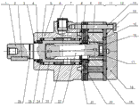
Fig. 1 is an embodiment's of the utility model structural representation.
Fig. 2 is a kind of structural representation of shaft seal in Fig. 1 embodiment.
Metal frame 1 ' in Fig. 2, back-up ring 2 ', caulking gum 3 '.
Fig. 3 is the another kind of structural representation of rotary shaft sealing in Fig. 1 embodiment.
embodiment one
The high-speed distributing cycloid hydraulic motor of the present embodiment, basic structure as shown in figures 1 and 3, comprise the housing 6 that is shaped with liquid entering hole and refluxing opening, the cycloidal pin wheel set being made up of stator 10, rotor 11 and pin tooth 12 and the flow-distribution mechanism being made up of the complex liquid baric flow road of flow dunnage 9 and the compound duct of rotor 11 are equipped with in one end of described housing 6, and the delivery outlet of its other end is supported with the output shaft 1 from stretching out in housing 6; The rotor 11 of described cycloidal pin wheel set engages with the external gear of couple axle 22 one end by internal spline, and the other end of described couple axle 22 is connected with output shaft 1 transmission; Its improvements are: described housing 6 is shaped with the step hole that rotary shaft sealing 4 is installed, described step hole is directly installed the cylindrical of rotary shaft sealing 4, described rotary shaft sealing 4 is installed by housing bore the one end that completely fills needle bearing and is installed, the installation dimension that described former and later two completely fill needle bearing is consistent, in front needle bearing 24 length, be greater than rear needle bearing 8, between described front needle bearing 24 and rear needle bearing 8, spacer ring 23 is installed, spacer ring 23 is conducive to guarantee the validity of installation between front needle bearing 24 and rear needle bearing 8.
The diameter of axle that the rotary shaft sealing 4 of described output shaft 1 seals and front and back completely fill between the installation diameter of axle of needle bearing thrust-bearing 5 and end ring 25 are installed, described thrust-bearing 5 is resisted against on the shaft shoulder of output shaft, and the shaft shoulder is to be formed by rotary shaft sealing 4 and the installation diameter of axle of front needle bearing 24.
One end that described couple axle 22 engages with rotor 11 is provided with compensation pad 17, and the cylindrical of described compensation pad 17 and the internal spline Spielpassung of rotor 11 are placed.
A kind of structure of described rotary shaft sealing 4 as shown in Figure 2, comprise metal frame 1 ', back-up ring 2 ', caulking gum 3 ', the profile of metal frame 1 ' is L shaped skeleton, formed by steel plate punched, in order to guarantee global stability and the rigidity of seal ring, described L shaped skeleton adopts heat treatment process to strengthen intensity and rigidity, and described L shaped skeleton is included in caulking gum 3 ', it is exposed structure that L shaped skeleton leans against hydraulic oil pressure surface, and steel surface does not have rubber packing material.Caulking gum 3 ' is made lip structure with output shaft 1 contact position, increases by a back-up ring 2 at lip and L shaped skeleton, and described back-up ring 2 is made up of polytetrafluoroethylmaterial material and is sealed and contact with output shaft 1.
The another kind of structure of described rotary shaft sealing 4 as shown in Figure 3, comprises sealer 1 in Fig. 3 ", metal frame 2 ", metal frame face 2 " and-1.Metal frame 1 " profile be L shaped skeleton; formed by steel plate punched; in order to guarantee global stability and the rigidity of seal ring; described L shaped skeleton adopts heat treatment process to strengthen intensity and rigidity; described L shaped skeleton is included in caulking gum 1 " in, L shaped skeleton leans against hydraulic oil pressure surface 2 "-1 for exposed structure; steel surface does not have rubber packing material; be conducive to rotary shaft sealing 4 and be arranged on the precision in the hole of housing 6; guarantee the conformity that lip contacts with output shaft 1, thus assurance output shaft 1 rotary seal type.In the time that rotary shaft sealing 4 is installed, pressing Fig. 3 arrow place, guarantee installation precision and the conformity of rotary shaft sealing 4, can more further guarantee shaft seal running accuracy.
Facts have proved, the structure of the high-speed distributing cycloid hydraulic motor of the present embodiment is conducive to the reliable of the installation of rotary shaft sealing and sealability, and the shaft seal structure of employing is also conducive to bear high pressure.It is simple that improvement structure of the present utility model makes motor axis of rotation be sealed seal structure, assembles simple and easyly, reduced due to the many unreliable factors that cause with assembly relation complexity of part, strengthened the reliability of sealing, saving user cost.
In addition to the implementation, the utility model can also have other mode of executions, and all employings are equal to the technological scheme of replacement or equivalent transformation formation, all drop on the protection domain of the utility model requirement.
Claims (7)
1.
a kind of high-speed distributing cycloid hydraulic motor, comprise the housing that is shaped with liquid entering hole and refluxing opening, the cycloidal pin wheel set being made up of stator, rotor and pin tooth and the flow-distribution mechanism being made up of the complex liquid baric flow road of flow dunnage and the compound duct of rotor are equipped with in one end of described housing, and the delivery outlet of its other end is supported with the output shaft from stretching out in housing; The rotor of described cycloidal pin wheel set engages with the external gear of couple axle one end by internal spline, and the other end of described couple axle is connected with output shaft transmission; It is characterized in that: described housing is shaped with the step hole that rotary shaft sealing is installed, described step hole is directly installed the cylindrical of rotary shaft sealing, described rotary shaft sealing is installed by housing bore the one end that completely fills needle bearing and is installed, the installation dimension that described former and later two completely fill needle bearing is consistent, and front end props up to fully support and in dress needle bearing length, is greater than rear end and props up and fully support dress needle bearing.
2.
high-speed distributing cycloid hydraulic motor according to claim 1, is characterized in that: described front and back completely fill spacer ring is installed between needle bearing.
3.
high-speed distributing cycloid hydraulic motor according to claim 2, it is characterized in that: the rotary shaft sealing sealing diameter of axle of described output shaft and front and back completely fill between the needle bearing installation diameter of axle thrust-bearing and end ring are installed, and described thrust-bearing is resisted against on the shaft shoulder of output shaft.
4.
high-speed distributing cycloid hydraulic motor according to claim 3, is characterized in that: one end that described couple axle engages with rotor is provided with compensation pad.
5.
high-speed distributing cycloid hydraulic motor according to claim 1, is characterized in that: described rotary shaft sealing has L shaped skeleton, and described L shaped skeleton is included in caulking gum, and it is exposed structure that L shaped skeleton leans against hydraulic oil pressure surface.
6.
high-speed distributing cycloid hydraulic motor according to claim 5, is characterized in that: described rotary shaft sealing increases at lip and L shaped skeleton that a polytetrafluoroethylmaterial material is made and seal with output shaft the back-up ring contacting.
7.
high-speed distributing cycloid hydraulic motor according to claim 6, is characterized in that: the L shaped skeleton of described rotary shaft sealing is formed by steel plate punched, and adopts heat treatment process to process.
Priority Applications (1)
| Application Number | Priority Date | Filing Date | Title |
|---|---|---|---|
| CN201420012956.9U CN203685462U (en) | 2014-01-09 | 2014-01-09 | High-speed flow distribution cycloid hydraulic motor |
Applications Claiming Priority (1)
| Application Number | Priority Date | Filing Date | Title |
|---|---|---|---|
| CN201420012956.9U CN203685462U (en) | 2014-01-09 | 2014-01-09 | High-speed flow distribution cycloid hydraulic motor |
Publications (1)
| Publication Number | Publication Date |
|---|---|
| CN203685462U true CN203685462U (en) | 2014-07-02 |
Family
ID=51007374
Family Applications (1)
| Application Number | Title | Priority Date | Filing Date |
|---|---|---|---|
| CN201420012956.9U Expired - Lifetime CN203685462U (en) | 2014-01-09 | 2014-01-09 | High-speed flow distribution cycloid hydraulic motor |
Country Status (1)
| Country | Link |
|---|---|
| CN (1) | CN203685462U (en) |
Cited By (2)
| Publication number | Priority date | Publication date | Assignee | Title |
|---|---|---|---|---|
| CN106762387A (en) * | 2017-01-06 | 2017-05-31 | 镇江大力液压马达股份有限公司 | A kind of body shell positioning high-speed distributing cycloid hydraulic motor with protecgulum |
| CN106870274A (en) * | 2017-04-15 | 2017-06-20 | 镇江大力液压马达股份有限公司 | A kind of big radial load supporting plane distributing cycloid hydraulic motor |
-
2014
- 2014-01-09 CN CN201420012956.9U patent/CN203685462U/en not_active Expired - Lifetime
Cited By (2)
| Publication number | Priority date | Publication date | Assignee | Title |
|---|---|---|---|---|
| CN106762387A (en) * | 2017-01-06 | 2017-05-31 | 镇江大力液压马达股份有限公司 | A kind of body shell positioning high-speed distributing cycloid hydraulic motor with protecgulum |
| CN106870274A (en) * | 2017-04-15 | 2017-06-20 | 镇江大力液压马达股份有限公司 | A kind of big radial load supporting plane distributing cycloid hydraulic motor |
Similar Documents
| Publication | Publication Date | Title |
|---|---|---|
| CN201057122Y (en) | Strong-sealing high-speed stream cycloid hydraulic motor and high-pressure rotating shaft seal | |
| CN101566149A (en) | Master-auxiliary vane pump and stator decompression method | |
| CN203685462U (en) | High-speed flow distribution cycloid hydraulic motor | |
| CN202937402U (en) | Radial support shaft valve wagon-flow allocation cycloid hydraulic motor | |
| CN204327396U (en) | Compact axial flow distribution cycloid hydraulic motor with short shell | |
| CN103696907B (en) | Brevicone axon is to compact high-speed distributing cycloid hydraulic motor | |
| CN202900558U (en) | Inclined-shaft type ration plunger pump | |
| CN101144525A (en) | Compact hydraulic motor gear reducer | |
| CN206571619U (en) | A kind of axle valve flow distribution cycloid hydraulic motor | |
| CN102828895B (en) | Radial support axle valve flow distribution cycloid hydraulic motor | |
| CN2883735Y (en) | Embedded high temp geared pump | |
| CN200996353Y (en) | High-pressure cycloidal hydraulic motor with large torsional moment | |
| CN102797622B (en) | Cycloid hydraulic motor of shaft-valve flow-distribution type | |
| CN106762609B (en) | A kind of high-tension shielding Gerotor pump | |
| CN202149024U (en) | Inner-engaged gear pump and gap filling component | |
| CN205226168U (en) | Hydraulic braking device | |
| CN103726983A (en) | High-speed flow distribution cycloid hydraulic motor | |
| CN202381250U (en) | Rear shaft output plane valving cycloidal hydraulic motor | |
| CN106438680A (en) | High-pressure gear pump bearing with sealing structure | |
| CN203685464U (en) | Axially compact high-speed flow distribution cycloid hydraulic motor with short shell body | |
| CN109441709B (en) | Compact type large-torque anti-pollution gear hydraulic motor | |
| CN105673315A (en) | Integral flange axial flow allocation cycloid hydraulic motor | |
| CN204226099U (en) | A kind of integral (type) flange axle distributing cycloid hydraulic motor | |
| CN210919330U (en) | Low-speed large-torque cycloid hydraulic motor | |
| CN103742353B (en) | Flat porting cycloid hydraulic pressure motor |
Legal Events
| Date | Code | Title | Description |
|---|---|---|---|
| C14 | Grant of patent or utility model | ||
| GR01 | Patent grant | ||
| CX01 | Expiry of patent term |
Granted publication date: 20140702 |
|
| CX01 | Expiry of patent term |