CN203684999U - Flexible lifting gate - Google Patents
Flexible lifting gate Download PDFInfo
- Publication number
- CN203684999U CN203684999U CN201320869152.6U CN201320869152U CN203684999U CN 203684999 U CN203684999 U CN 203684999U CN 201320869152 U CN201320869152 U CN 201320869152U CN 203684999 U CN203684999 U CN 203684999U
- Authority
- CN
- China
- Prior art keywords
- steel wire
- gate
- pulley
- door frame
- fixed
- Prior art date
- Legal status (The legal status is an assumption and is not a legal conclusion. Google has not performed a legal analysis and makes no representation as to the accuracy of the status listed.)
- Expired - Lifetime
Links
- 229910000831 Steel Inorganic materials 0.000 claims abstract description 31
- 239000010959 steel Substances 0.000 claims abstract description 31
- 238000010276 construction Methods 0.000 claims description 4
- 239000000203 mixture Substances 0.000 claims description 3
- 238000000034 method Methods 0.000 abstract description 4
- 238000004804 winding Methods 0.000 abstract 3
- 239000000428 dust Substances 0.000 description 4
- 230000000694 effects Effects 0.000 description 4
- 238000010422 painting Methods 0.000 description 4
- 230000000712 assembly Effects 0.000 description 2
- 238000000429 assembly Methods 0.000 description 2
- 230000002146 bilateral effect Effects 0.000 description 2
- 238000010586 diagram Methods 0.000 description 2
- 238000009413 insulation Methods 0.000 description 2
- 238000004519 manufacturing process Methods 0.000 description 2
- 239000000463 material Substances 0.000 description 2
- 241000196324 Embryophyta Species 0.000 description 1
- 238000009825 accumulation Methods 0.000 description 1
- 238000005516 engineering process Methods 0.000 description 1
- 230000005484 gravity Effects 0.000 description 1
- 230000007774 longterm Effects 0.000 description 1
- 239000003973 paint Substances 0.000 description 1
- 239000000843 powder Substances 0.000 description 1
- 239000004576 sand Substances 0.000 description 1
- 230000001360 synchronised effect Effects 0.000 description 1
Images


Abstract
The utility model discloses a flexible lifting gate, and aims to solve the problem of low running reliability of the conventional flexible lifting gate. The flexible lifting gate comprises a gate body, a gate frame, a braking mechanism and a lifting mechanism, wherein a base frame is arranged at the lower part of the gate body; the gate frame comprises a side gate frame and an upper gate frame; the braking mechanism is mounted between the gate body and the side gate frame; the lifting mechanism consists of a driving unit, a steel wire rope winding device, two steel wire ropes and two pulley components; the driving unit and the steel wire rope winding device are fixed on the upper gate frame; the flexible lifting gate is characterized in that one end of each of the steel wire ropes is fixed on the upper gate frame, and the other end of the steel wire rope bypasses the corresponding pulley component and is wound on the steel wire rope winding device; the pulley components comprise fixed pulleys, movable pulleys and movable pulley brackets; the movable pulleys are mounted on the movable pulley brackets; the movable pulley brackets are mounted at the upper part of the base frame. According to the utility model, the smoothness and stability of the gate lifting process is guaranteed, and an accident of gate dropping is effectively avoided.
Description
Technical field
The utility model relates to a kind of flexible lifting door, and especially a kind of flexible hoisting front that is applicable to equipment Manufacturing painting workshop belongs to building moving door and window technical field.
Background technology
The flexible hoisting front of stacked frame construction, the generally dignity material using flexible material as door, underframe adopts movable truss, when opening, by the driven by motor wire rope (or elevator belt) that is arranged on doorframe top, underframe is up sling door body, door-plate stacks from the bottom up layer by layer, is deposited in the top of doorframe.This flexible hoisting front have keep out the wind, the feature such as insulation, sound insulation, be often used as the Painting Shop gate of bulk storage plant and equipment Manufacturing.
Shown in accompanying drawing 1~4 is a kind of Painting Shop flexible hoisting front, its hoist rope 2 lower end fixed points are positioned at the bottom of underframe 4, because of the hoist point of underframe 4 below in underframe center of gravity, underframe 4, hanging existence front and back deflection problem in the process of liter, causes the roller 4-2 on underframe both sides lifting leading truck 4-1 and the guide rail 3-1 on doorframe 3 that catching phenomenon occurs; Simultaneously, because its door-plate is multilayer beam structure, in the time of Painting Shop operation, the steel sand, the paint powder that splash can be piled up on each layer of crossbeam, so long-term accumulation must cause the increase of gate weight, when the weight at gate exceeds after hoist rope 2 assumed loads, can cause the serious accident that wire rope disconnects, door body 1 falls; In addition, the roller 4-2 on this flexible hoisting front underframe both sides lifting leading truck 4-1 is in the serious working environment of dust pollution, and dust falls into roller rotary part and very easily causes the damage of roller or stuck.As can be seen here, not only there is a problem for the easy clamping stagnation of body lifting in the flexible hoisting front shown in accompanying drawing 1~4, but also exists the major safety risks that a body falls.
Utility model content
The purpose of this utility model is the drawback for prior art, the flexible hoisting front that provides a kind of and ensure a body lifting process steady and smooth, can effectively avoid a body falling accident to occur.
Problem described in the utility model realizes with following technical proposals:
A kind of flexible hoisting front, it comprises a body, doorframe, arrestment mechanism and Diao Sheng mechanism, described Men Tiwei can stacked s crossbeam frame structure, in door body bottom, underframe is set, described doorframe comprises side door frame and upper door frame, described arrestment mechanism is arranged between Men Tiyu side door frame, described Diao Sheng mechanism is by driver element, two wire rope that steel wire disk cable device and left and right are arranged and two cover pulley assemblies compositions, described driver element and steel wire disk cable device are equipped, they are all fixed on upper door frame, its special feature is: described wire rope one end is fixed on upper door frame, the other end is wrapped on steel wire disk cable device after walking around pulley assembly, described pulley assembly comprises fixed pulley, movable pulley and moving pulley bracket, described fixed pulley is fixed on upper door frame, described movable pulley is arranged on moving pulley bracket, described moving pulley bracket is arranged on the top of underframe.
Above-mentioned flexible hoisting front, described moving pulley bracket one end is provided with hinged seat, and the other end is provided with braking arm-tie, and described hinged seat is fixed on the underframe of trussed construction, and described braking arm-tie and arrestment mechanism are equipped.
Above-mentioned flexible hoisting front, described steel wire disk cable device is provided with baffles, and described baffles is positioned at the axial centre position of steel wire disk cable device.
Above-mentioned flexible hoisting front, described both sides doorframe is provided with guide rail, and described guide rail is " work " word steel work, and they are arranged on the inner side of both sides doorframe.
Above-mentioned flexible hoisting front, the described underframe left and right sides is equipped with lifting leading truck, and described lifting leading truck outboard end is symmetrical arranged two closed type bearings, the guide rail on described closed type bearing and side door frame.
The utility model is provided with movable pulley in Diao Sheng mechanism, and making the load reduction that wire rope bears is original half, has reduced the risk that wire rope disconnection, door body fall.Movable pulley of the present utility model is hinged by moving pulley bracket and underframe, can adjust door body both sides non-equilibrium state by moving pulley bracket rotation within the specific limits, avoids tilting to cause both sides lifting leading truck and guide rail catching phenomenon because of door body.The utility model is provided with braking arm-tie on moving pulley bracket, in the time that movable pulley is sling by wire rope, moving pulley bracket rotates around jointed shaft, drives braking arm-tie to move upward, by the lockup state of pulling force brake off mechanism of braking arm-tie, a door body underframe rises thereupon; In the time that door body underframe falls to ground or wire rope disconnection accident occurs, the pulling force that wire rope is applied on movable pulley disappears, moving pulley bracket rotates backward around jointed shaft under self gravitation effect, braking arm-tie disappears to the pulling force of arrestment mechanism, arrestment mechanism recovers lockup state, make the underframe of a body be fixed on both sides doorframe, the stop motion of door body is in lockup state.The utility model is provided with baffles on steel wire disk cable device, makes two wire rope in the stacked coiling of steel wire disk cable device bilateral symmetry, has avoided two wire rope to be wound around mutually the interference causing; The utility model is symmetrical arranged two closed type bearings at lifting leading truck outboard end, coordinates the guide effect that realizes the lifting of door body by closed type bearing with guide rail, has solved dust and has fallen into roller damage or the stuck problem that roller rotary part causes.In a word, the utility model has not only ensured the steady and smooth of door body lifting process, and has effectively avoided the generation of door body falling accident.
Brief description of the drawings
Below in conjunction with accompanying drawing, the utility model is described in further detail.
Fig. 1 is existing flexible hoisting front structural representation;
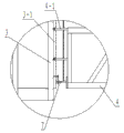
Fig. 2 is A place structure enlarged drawing in Fig. 1;
Fig. 3 is underframe, lifting leading truck and the guide rail matching relationship schematic diagram of existing flexible hoisting front;
Fig. 4 is that hanging of existing flexible hoisting front rises structural scheme of mechanism;
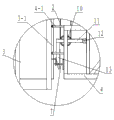
Fig. 5 is the utility model structural representation;
Fig. 6 is B place structure enlarged drawing in Fig. 5;
Fig. 7 is underframe of the present utility model, lifting leading truck and guide rail matching relationship schematic diagram;
Fig. 8 is that of the present utility model hanging rises structural scheme of mechanism.
In figure, each list of reference numerals is: 1, Men Ti, 2, wire rope, 3, side door frame, 3-1, guide rail, 4, underframe, 4-1, lifting leading truck, 4-2, roller, 4-3, closed type bearing, 5, driver element, 6, fixed pulley, 7, arrestment mechanism, 8, steel wire disk cable device, 9, upper door frame, 10, movable pulley, 11, moving pulley bracket, 12, hinged seat, 13, braking arm-tie, 14, baffles.
Detailed description of the invention
Referring to Fig. 5, the utility model comprises a body 1, doorframe, arrestment mechanism 7 and Diao Sheng mechanism, described door body 1 is can stacked s crossbeam frame structure, in door body 1 bottom, underframe 4 is set, described doorframe comprises side door frame 3 and upper door frame 9, described arrestment mechanism 7 is arranged between a body 1 and side door frame 3, described Diao Sheng mechanism is by driver element 5, two wire rope 2 that steel wire disk cable device 8 and left and right are arranged and two cover pulley assemblies compositions, described driver element 5 is equipped with steel wire disk cable device 8, they are all fixed on upper door frame 9, its special feature is, described wire rope 2 one end are fixed on upper door frame 9, the other end is wrapped on steel wire disk cable device 8 after walking around pulley assembly, described pulley assembly comprises fixed pulley 6, movable pulley 10 and moving pulley bracket 11, described fixed pulley is fixed on upper door frame 9, described movable pulley 10 is arranged on moving pulley bracket 11, described moving pulley bracket 11 is arranged on the top of underframe 4.
Referring to Fig. 6, Fig. 7, moving pulley bracket of the present utility model 11 one end are provided with hinged seat 12, and the other end is provided with braking arm-tie 13, and described hinged seat 12 is fixed on the underframe 4 of trussed construction, and described braking arm-tie 13 is equipped with arrestment mechanism 7; Underframe of the present utility model 4 left and right sides are equipped with lifting leading truck 4-1, and described lifting leading truck 4-1 outboard end is symmetrical arranged two closed type bearing 4-3, and described closed type bearing 4-3 mates with the guide rail 3-1 on side door frame 3; Described guide rail 3-1 is " work " word steel work, and they are arranged on the inner side of both sides doorframe 3.
Referring to Fig. 8, steel wire disk cable device 8 of the present utility model is provided with baffles 14, and described baffles 14 is positioned at the axial centre position of steel wire disk cable device 8.
Referring to Fig. 1~Fig. 8, the utility model is provided with movable pulley 10 in Diao Sheng mechanism, and making the load reduction that wire rope 2 bears is original half, has reduced the risk that wire rope 2 disconnects, door body falls.Movable pulley 10 of the present utility model is hinged by moving pulley bracket 11 and underframe 4, can adjust door body 1 both sides non-equilibrium state by moving pulley bracket 11 rotation within the specific limits, avoid tilting to cause both sides lifting leading truck 4-1 and guide rail 3-1 catching phenomenon because of door body 1.The utility model is provided with braking arm-tie 13 on moving pulley bracket 11, in the time that movable pulley 10 is sling by wire rope 2, moving pulley bracket 11 rotates around jointed shaft, drive braking arm-tie 13 to move upward, by the lockup state of pulling force brake off mechanism 7 of braking arm-tie 13, the underframe 4 of door body 1 rises thereupon; In the time that underframe 4 falls to ground or wire rope 2 disconnection accident occurs, the pulling force that wire rope 2 is applied on movable pulley 10 disappears, moving pulley bracket 11 rotates backward around jointed shaft under self gravitation effect, braking arm-tie 13 disappears to the pulling force of arrestment mechanism 7, arrestment mechanism 7 recovers lockup state, underframe 4 is fixed on both sides doorframe 3, and 1 stop motion of door body is in lockup state.The utility model is provided with baffles 14 on steel wire disk cable device 8, in the time that door body 1 hoists, two wire rope 2 are to middle automatic coiling, touch after baffles 14 simultaneously, the synchronous backward coiling second layer, make the bilateral symmetry stacked coiling of two wire rope 2 at steel wire disk cable device 8, avoided lengthening because adding the rear wire rope 2 of movable pulley 10 generation of two wire rope 2 interference bringing; The utility model is symmetrical arranged two closed type bearing 4-3 at lifting leading truck 4-1 outboard end, coordinate a guide effect that realizes door body 1 lifting with the guide rail 3-1 of " work " word steel work by closed type bearing 4-3, what solved that existing flexible hoisting front exists damages or stuck problem because dust falls into the roller that roller 4-2 rotary part causes.
Claims (5)
1. a flexible hoisting front, it comprises a body (1), doorframe, arrestment mechanism (7) and Diao Sheng mechanism, described door body (1) is can stacked s crossbeam frame structure, in door body (1) bottom, underframe (4) is set, described doorframe comprises side door frame (3) and upper door frame (9), described arrestment mechanism (7) is arranged between a body (1) and side door frame (3), described Diao Sheng mechanism is by driver element (5), two wire rope (2) that steel wire disk cable device (8) and left and right are arranged and two cover pulley assembly compositions, described driver element (5) is equipped with steel wire disk cable device (8), they are all fixed on upper door frame (9), it is characterized in that, described wire rope (2) one end is fixed on upper door frame (9), the other end is wrapped on steel wire disk cable device (8) after walking around pulley assembly, described pulley assembly comprises fixed pulley (6), movable pulley (10) and moving pulley bracket (11), described fixed pulley is fixed on upper door frame (9), described movable pulley (10) is arranged on moving pulley bracket (11), described moving pulley bracket (11) is arranged on the top of underframe (4).
2. a kind of flexible hoisting front according to claim 1, it is characterized in that, described moving pulley bracket (11) one end is provided with hinged seat (12), the other end is provided with braking arm-tie (13), described hinged seat (12) is fixed on the underframe (4) of trussed construction, and described braking arm-tie (13) is equipped with arrestment mechanism (7).
3. a kind of flexible hoisting front according to claim 1 and 2, is characterized in that, described steel wire disk cable device (8) is provided with baffles (14), and described baffles (14) is positioned at the axial centre position of steel wire disk cable device (8).
4. a kind of flexible hoisting front according to claim 3, is characterized in that, guide rail (3-1) is " work " word steel work, and they are arranged on the inner side of both sides doorframe (3).
5. a kind of flexible hoisting front according to claim 4, it is characterized in that, described underframe (4) left and right sides is equipped with lifting leading truck (4-1), described lifting leading truck (4-1) outboard end is symmetrical arranged two closed type bearings (4-3), and described closed type bearing (4-3) mates with the guide rail (3-1) on side door frame (3).
Priority Applications (1)
| Application Number | Priority Date | Filing Date | Title |
|---|---|---|---|
| CN201320869152.6U CN203684999U (en) | 2013-12-27 | 2013-12-27 | Flexible lifting gate |
Applications Claiming Priority (1)
| Application Number | Priority Date | Filing Date | Title |
|---|---|---|---|
| CN201320869152.6U CN203684999U (en) | 2013-12-27 | 2013-12-27 | Flexible lifting gate |
Publications (1)
| Publication Number | Publication Date |
|---|---|
| CN203684999U true CN203684999U (en) | 2014-07-02 |
Family
ID=51006918
Family Applications (1)
| Application Number | Title | Priority Date | Filing Date |
|---|---|---|---|
| CN201320869152.6U Expired - Lifetime CN203684999U (en) | 2013-12-27 | 2013-12-27 | Flexible lifting gate |
Country Status (1)
| Country | Link |
|---|---|
| CN (1) | CN203684999U (en) |
Cited By (1)
| Publication number | Priority date | Publication date | Assignee | Title |
|---|---|---|---|---|
| CN113431470A (en) * | 2021-06-15 | 2021-09-24 | 上海交通大学 | Flexible partition door for large-scale high-low temperature environment simulation test system |
-
2013
- 2013-12-27 CN CN201320869152.6U patent/CN203684999U/en not_active Expired - Lifetime
Cited By (1)
| Publication number | Priority date | Publication date | Assignee | Title |
|---|---|---|---|---|
| CN113431470A (en) * | 2021-06-15 | 2021-09-24 | 上海交通大学 | Flexible partition door for large-scale high-low temperature environment simulation test system |
Similar Documents
| Publication | Publication Date | Title |
|---|---|---|
| CN205099211U (en) | Hoist anti -swing device | |
| AU2011101553A4 (en) | Emergency escape device for elevator | |
| CN200954972Y (en) | Portal-type construction lifter for both person and goods | |
| CN208916761U (en) | A kind of articulated arm lift | |
| CN202614492U (en) | Elevator buffer testing equipment | |
| CN203684999U (en) | Flexible lifting gate | |
| CN104192681B (en) | A kind of building hoist integration actuating device | |
| CN206126699U (en) | Multi -functional portable lifting machine | |
| CN210418839U (en) | Safe energy-saving elevator | |
| CN203558395U (en) | Hoisting mechanism of stacker loading platform | |
| CN202575639U (en) | Pneumatic elevator | |
| CN205222495U (en) | Dynamic brake equipment's of hoist link gear | |
| CN205873697U (en) | Control hoist rise to rise with differential actuating mechanism of mixture of dolly sideslip | |
| CN210528295U (en) | Multifunctional transportation device | |
| CN205222496U (en) | Dynamic brake equipment's of hoist driving brake frame | |
| CN201703947U (en) | Cantilever type lifter | |
| CN204980736U (en) | Dedicated pair of cage elevator of building site construction | |
| CN107572428A (en) | A kind of electronic heavy lift machinery device | |
| CN107188036A (en) | Hoisting trolley and crane | |
| CN209242547U (en) | Single drum rubbish hangs structure | |
| CN107572434B (en) | Safe tackling system | |
| CN102642753B (en) | Pneumatic elevator | |
| CN206014294U (en) | Landing power-off and the double speed crane of overload freight weight limit | |
| CN206634899U (en) | One kind forces reel elevator | |
| CN205187593U (en) | Lifting device |
Legal Events
| Date | Code | Title | Description |
|---|---|---|---|
| C14 | Grant of patent or utility model | ||
| GR01 | Patent grant | ||
| CX01 | Expiry of patent term |
Granted publication date: 20140702 |
|
| CX01 | Expiry of patent term |