CN203664517U - V-type curved molding stamping die - Google Patents
V-type curved molding stamping die Download PDFInfo
- Publication number
- CN203664517U CN203664517U CN201320819417.1U CN201320819417U CN203664517U CN 203664517 U CN203664517 U CN 203664517U CN 201320819417 U CN201320819417 U CN 201320819417U CN 203664517 U CN203664517 U CN 203664517U
- Authority
- CN
- China
- Prior art keywords
- movable block
- bending
- compression mould
- patrix
- shaping punching
- Prior art date
- Legal status (The legal status is an assumption and is not a legal conclusion. Google has not performed a legal analysis and makes no representation as to the accuracy of the status listed.)
- Expired - Fee Related
Links
Images


Landscapes
- Press Drives And Press Lines (AREA)
Abstract
The utility model discloses a V-type curved molding stamping die which comprises an upper die and a lower die connected with the upper die. The upper die comprises an upper die base and an upper clamping plate connected to the upper die base, and the upper die further comprises a guiding movable block and a curving male device connected with the guiding movable block; the guiding movable block is arranged on one side of the upper clamping plate, and the bottom of the curving male device is in a V type. The V-type curved molding stamping die is simple in structure and convenient to operate, cost is reduced, and the production efficiency is improved.
Description
Technical field
The utility model relates to a kind of diel, specifically, relates to the bent shaping punching compression mould of a kind of V.
Background technology
Hardware products is in the time carrying out the bent bending and molding of V, and traditional diel is all generally first to loose core, and the slotting tool on recycling mould both sides carries out bending by force, finally completes the shaping work of product, inefficiency; And the complex structure of traditional diel, cost of manufacture is high.
Utility model content
For solving the problems of the technologies described above, the purpose of this utility model is to provide a kind of simple in structure, easy to operate, bent shaping punching compression mould of V of reducing costs and enhancing productivity.
For achieving the above object, the technical solution of the utility model is as follows: the bent shaping punching compression mould of a kind of V, comprise patrix and the counterdie that is connected described patrix, described patrix comprises upper bolster and the train wheel bridge that is connected described upper bolster, and described patrix also comprises guiding movable block and the bending public affairs that are connected described guiding movable block; Described guiding movable block is arranged at a side of described train wheel bridge, and the bottom of described bending public affairs is V-shaped.
Further, the opposite side of described train wheel bridge is also provided with the limited block for limiting the public position of described bending.
Further, described guiding movable block comprises movable block and the spring that is connected described movable block.
Further, between described guiding movable block and bending Gongzhi, be fixedly connected with by contiguous block.
Further, described counterdie comprises die shoe and is arranged at the lower bolster on described die shoe.
Further, be provided with V-type forming tank on described lower bolster, described forming tank and described bending public affairs match.
Adopt technique scheme, the beneficial effect of technical solutions of the utility model is: the shaping work of whole product, and utilize upper and lower mould to match, just can realize by guiding movable block and bending public affairs, not only simple in structure, and also easy to operate; Reduce cost simultaneously, improved operating efficiency.
Accompanying drawing explanation
In order to be illustrated more clearly in the technical scheme in the utility model embodiment technology, to the accompanying drawing of required use in embodiment technical description be briefly described below, apparently, accompanying drawing in the following describes is only embodiment more of the present utility model, for those of ordinary skills, do not paying under the prerequisite of creative work, can also obtain according to these accompanying drawings other accompanying drawing.
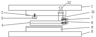
Fig. 1 is the die opening state figure of the bent shaping punching compression mould of a kind of V of the utility model;
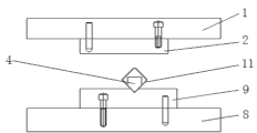
Fig. 2 is the mold closing state diagram of the bent shaping punching compression mould of a kind of V of the utility model;
Fig. 3 is the top view of the bent shaping punching compression mould of a kind of V of the utility model;
Fig. 4 is one of machining sketch chart of product in the bent shaping punching compression mould of a kind of V of the utility model;
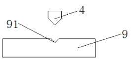
Fig. 5 be product in the bent shaping punching compression mould of a kind of V of the utility model machining sketch chart two;
Fig. 6 is the cooperation schematic diagram of the public and lower bolster of bending in the bent shaping punching compression mould of a kind of V of the utility model.
Wherein, 1, upper bolster, 2, train wheel bridge, 31, movable block, 32, spring, 4, bending public affairs, 5, limited block, 6, contiguous block, 7, screw, 8, die shoe, 9, lower bolster, 10, semi-finished product, 11, product.
The specific embodiment
Below in conjunction with the accompanying drawing in the utility model embodiment, the technical scheme in the utility model embodiment is clearly and completely described, obviously, described embodiment is only the utility model part embodiment, rather than whole embodiment.Based on the embodiment in the utility model, those of ordinary skills are not making the every other embodiment obtaining under creative work prerequisite, all belong to the scope of the utility model protection.
As Fig. 1-3, shown in, the bent shaping punching compression mould of a kind of V, comprises patrix and the counterdie that is connected patrix, and patrix comprises upper bolster 1 and the train wheel bridge 2 that is connected upper bolster 1, and patrix also comprises guiding movable block and the bending public affairs 4 that are connected the movable block that leads; Guiding movable block is arranged at a side of train wheel bridge 2, and the bottom of bending public affairs 4 is V-shaped, as shown in Figure 6.
The opposite side of train wheel bridge 2 is also provided with the limited block 5 for limiting public 4 positions of bending; Wherein, guiding movable block comprises movable block 31 and the spring 32 that is connected movable block 31, and spring 32 is arranged on upper bolster 1, is fixedly connected with, then locks by screw 7 between guiding movable block and bending public affairs 4 by contiguous block 6.
Counterdie comprises die shoe 8 and is arranged at the lower bolster 9 on die shoe 8; On lower bolster 9, be provided with V-type forming tank, forming tank and bending public affairs match, as shown in Figure 6.
Introduce operation principle of the present utility model below: as Fig. 1, shown in Fig. 4, before punching press, the semi-finished product of processed product 10 are positioned on lower bolster 9, because movable block 31 is subject to the active force of spring 32, the bending public 4 that makes patrix with limited block 5 in released state, in the time that patrix is descending, because bending public affairs 4 touch the semi-finished product 10 of lower bolster, now be subject to the resistance of counterdie, the whole movable part of patrix, movable block leads, start upwards to make a concession, mould continues descending, now patrix bending public affairs 4 touch limited block 5, patrix movable block 31 also touches upper bolster 1 bottom, product is just in time pressed in the forming tank of lower bolster 9 by bending public affairs 4, as Fig. 2, shown in Fig. 5, now complete the V-type bending technique of part, product 11 is coated in bending public affairs 4, in the time of mould die sinking, operator takes off product along the side of product the length direction of product (along).
By technique scheme, the beneficial effect of technical solutions of the utility model is: the shaping work of whole product, and utilize upper and lower mould to match, just can realize by guiding movable block and bending public affairs, not only simple in structure, and also easy to operate; Reduce cost simultaneously, improved operating efficiency; Meanwhile, bending is public to match with lower bolster, makes formed product more stable, and precision is high.
To the above-mentioned explanation of the disclosed embodiments, make professional and technical personnel in the field can realize or use the utility model.To be apparent for those skilled in the art to the multiple modification of these embodiment, General Principle as defined herein can, in the situation that not departing from spirit or scope of the present utility model, realize in other embodiments.Therefore, the utility model will can not be restricted to these embodiment shown in this article, but will meet the widest scope consistent with principle disclosed herein and features of novelty.
Claims (6)
1. the bent shaping punching compression mould of V, comprise patrix and the counterdie that is connected described patrix, described patrix comprises upper bolster and the train wheel bridge that is connected described upper bolster, it is characterized in that, described patrix also comprises guiding movable block and the bending public affairs that are connected described guiding movable block; Described guiding movable block is arranged at a side of described train wheel bridge, and the bottom of described bending public affairs is V-shaped.
2. the bent shaping punching compression mould of V according to claim 1, is characterized in that, the opposite side of described train wheel bridge is also provided with the limited block for limiting the public position of described bending.
3. the bent shaping punching compression mould of V according to claim 1, is characterized in that, described guiding movable block comprises movable block and the spring that is connected described movable block.
4. the bent shaping punching compression mould of V according to claim 3, is characterized in that, between described guiding movable block and bending Gongzhi, is fixedly connected with by contiguous block.
5. according to the bent shaping punching compression mould of the V described in claim 1 or 4, it is characterized in that, described counterdie comprises die shoe and is arranged at the lower bolster on described die shoe.
6. the bent shaping punching compression mould of V according to claim 5, is characterized in that, on described lower bolster, be provided with V-type forming tank, described forming tank and described bending public affairs match.
Priority Applications (1)
| Application Number | Priority Date | Filing Date | Title |
|---|---|---|---|
| CN201320819417.1U CN203664517U (en) | 2013-12-13 | 2013-12-13 | V-type curved molding stamping die |
Applications Claiming Priority (1)
| Application Number | Priority Date | Filing Date | Title |
|---|---|---|---|
| CN201320819417.1U CN203664517U (en) | 2013-12-13 | 2013-12-13 | V-type curved molding stamping die |
Publications (1)
| Publication Number | Publication Date |
|---|---|
| CN203664517U true CN203664517U (en) | 2014-06-25 |
Family
ID=50960850
Family Applications (1)
| Application Number | Title | Priority Date | Filing Date |
|---|---|---|---|
| CN201320819417.1U Expired - Fee Related CN203664517U (en) | 2013-12-13 | 2013-12-13 | V-type curved molding stamping die |
Country Status (1)
| Country | Link |
|---|---|
| CN (1) | CN203664517U (en) |
Cited By (1)
| Publication number | Priority date | Publication date | Assignee | Title |
|---|---|---|---|---|
| CN105057466A (en) * | 2015-09-01 | 2015-11-18 | 金牌模具(常熟)有限公司 | Novel stamping inverted-installed V-bending die |
-
2013
- 2013-12-13 CN CN201320819417.1U patent/CN203664517U/en not_active Expired - Fee Related
Cited By (1)
| Publication number | Priority date | Publication date | Assignee | Title |
|---|---|---|---|---|
| CN105057466A (en) * | 2015-09-01 | 2015-11-18 | 金牌模具(常熟)有限公司 | Novel stamping inverted-installed V-bending die |
Similar Documents
| Publication | Publication Date | Title |
|---|---|---|
| CN203592059U (en) | Composite die | |
| CN203991987U (en) | A kind of pedestal upset diel | |
| CN102962359A (en) | Bending mold for enclosed sheet metal parts | |
| CN203330235U (en) | Inner side face punching mechanism of stamping die | |
| CN203664517U (en) | V-type curved molding stamping die | |
| CN204276665U (en) | A kind of two action bender | |
| CN203526334U (en) | Multi-angle bending machine upper cutter | |
| CN203459527U (en) | Bending mold for manufacturing U-shaped workpiece | |
| CN203184415U (en) | Profiled stamping mold for cell phone integrated sheet | |
| CN203002929U (en) | Stamping die used for once forming of bridge notching, bending and stretch wrapping of work piece | |
| CN202701152U (en) | Guide rail front plate forming die | |
| CN202185522U (en) | Forming structure for side reshaping and side flanging of side panel in soft die | |
| CN203253815U (en) | Double pressing die | |
| CN202910174U (en) | Adjustable mould | |
| CN204486579U (en) | A kind of built-in side blow structure | |
| CN203592063U (en) | Continuously-stamping die | |
| CN203711620U (en) | Stretching die for automobile collector cover plate | |
| CN202762790U (en) | Bending device of H-shaped steel | |
| CN201684838U (en) | Forming mold structure for enclosing and forming product | |
| CN204700149U (en) | Disposable barb brake forming mould | |
| CN205341654U (en) | Simple and easy stamping die | |
| CN201639138U (en) | Small space continuous terminal stamping mold | |
| CN205253849U (en) | Light current case curb plate stamping die | |
| CN204276663U (en) | A kind of side direction material guide mechanism of continuous stamping die | |
| CN205599761U (en) | Price tablet blanking upgrades mould die board |
Legal Events
| Date | Code | Title | Description |
|---|---|---|---|
| C14 | Grant of patent or utility model | ||
| GR01 | Patent grant | ||
| CF01 | Termination of patent right due to non-payment of annual fee | ||
| CF01 | Termination of patent right due to non-payment of annual fee |
Granted publication date: 20140625 Termination date: 20181213 |