CN203656640U - Combined lamp - Google Patents
Combined lamp Download PDFInfo
- Publication number
- CN203656640U CN203656640U CN201320845614.0U CN201320845614U CN203656640U CN 203656640 U CN203656640 U CN 203656640U CN 201320845614 U CN201320845614 U CN 201320845614U CN 203656640 U CN203656640 U CN 203656640U
- Authority
- CN
- China
- Prior art keywords
- connector
- lamp
- interface
- lamp body
- lamp socket
- Prior art date
- Legal status (The legal status is an assumption and is not a legal conclusion. Google has not performed a legal analysis and makes no representation as to the accuracy of the status listed.)
- Expired - Fee Related
Links
Images


Abstract
The utility model relates to a combined lamp and can effectively solve the problems of short service life, simplicity for damage and environmental pollution of an existing lamp. The combined lamp comprises a lamp body, a connecting body and a lamp base, wherein the lamp body and the lamp base are rotationally mounted at the two ends of the connecting body to form a detachable structure; the connecting body is in a tubular structure with two open ends; a first fixing plate and a second fixing plate are mounted at the two ends in the connecting body respectively; a first plug is mounted at the lower part of the lamp body through a lead wire and inserted into a first interface on the first fixing plate; a second interface is arranged at the upper part of the lamp base; the first interface is connected with a second plug inserted into the second interface through a lead wire. The combined lamp is novel, unique, simple and reasonable in structure, easy to produce, low in cost, long in service life, convenient to use, good in effect and innovative.
Description
Technical field
The utility model relates to light fixture, particularly a kind of Assembled lamp.
Background technology
Light fixture is in the market all the integrative-structure that fluorescent tube and lamp socket form conventionally, need only badly, just can only throw away, and not only causes the waste of money, has also caused environmental pollution, inside light fixture, contains a large amount of noxious materials, deals with investment larger, exhausts the people and drains the treasury; In addition, the reason that affects light fixture service life is a lot, and temperature is one of the main reasons, and temperature is the main cause that affects electronic devices and components work and service life; The light fixture of this integrative-structure, heat rises, and itself sends very high heat in the time that power panel is worked again, add the heat of fluorescent tube or illuminator (load), two thermals source are added and cause service life short, flimsy problem, therefore, its improvement and bring new ideas is imperative.
Summary of the invention
For above-mentioned situation, for overcoming the defect of prior art, the object of the utility model is just to provide a kind of Assembled lamp, can effectively solve light fixture short service life, fragile, causes the problem of environmental pollution.
The technical scheme that the utility model solves is, comprise lamp body, connector and lamp socket, the two ends of connector are installed with respectively lamp body and lamp socket, form detachable structure, connector is the tubular structure of both ends open, in connector, the first fixed head and the second fixed head are equipped with respectively in two ends, the first plug is equipped with through wire in lamp body bottom, the first plug is inserted in the first interface on the first fixed head, the second interface is arranged at lamp socket top, and first interface is connected with the second plug being inserted in the second interface through wire.
The utility model novel structure uniqueness, advantages of simple, easily produces, and cost is low, and the life-span is long, easy to use, effective, is the innovation on light fixture.
Brief description of the drawings
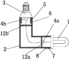
Fig. 1 is sectional front view of the present utility model.
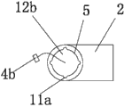
Fig. 2 is the front view of the utility model connector.
Fig. 3 is the top view of the utility model connector.
Fig. 4 is the right view of the utility model connector.
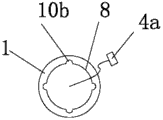
Fig. 5 is the left view of the utility model lamp body.
Fig. 6 is the upward view of the utility model lamp socket.
Fig. 7 is use state diagram of the present utility model.
Detailed description of the invention
Below in conjunction with accompanying drawing, detailed description of the invention of the present utility model is described in further detail.
Provided by Fig. 1-7, the utility model comprises lamp body, connector and lamp socket, it is characterized in that, the two ends of connector 2 are installed with respectively lamp body 1 and lamp socket 3, form detachable structure, the tubular structure that connector 2 is both ends open, the first fixed head 12a and the second fixed head 12b are equipped with respectively in the interior two ends of connector 2, the first plug 4a is equipped with through wire in lamp body 1 bottom, the first plug 4a is inserted in the first interface 9a on the first fixed head 12a, the second interface 9b is arranged at lamp socket 3 tops, and first interface 9a is connected with the second plug 4b being inserted in the second interface 9b through wire.
In order to ensure result of use, described connector 2 is L shaped tubular structure;
Described connector 2 is in the first connector 2a at the second connector 2b two ends, the detachable structure that the 3rd connector 2c forms by the second connector 2b of " one " font and spinning;
On the inwall of described lamp body 1 bottom, have the first internal thread 8, on the outer wall of connector 2 one end, have first external screw thread 7 corresponding with the first internal thread 8, lamp body 1 through the first internal thread 8 and the first external screw thread 7 spinnings on the end of connector 2;
On the inwall of described lamp body 1 bottom, be evenly equipped with the first stopper slot 10b, on one end outer wall of connector 2, have the first spacing preiection 10a corresponding with the first stopper slot 10b;
On the outer wall on described lamp socket 3 tops, have the second external screw thread 6, on the inwall of connector 2 one end, have second internal thread 5 corresponding with the second external screw thread 6, lamp socket 3 through the second external screw thread 6 and the second internal thread 5 spinnings on connector 2 ends;
On the outer wall on described lamp socket 3 tops, be evenly equipped with the second spacing preiection 11b, on one end inwall of connector 2, have the second stopper slot 11a corresponding with the second spacing preiection 11b.
When the utility model uses, lamp socket 3 is arranged on power interface, owing to having increased connector 2 between lamp socket 3 and lamp body 1, effectively heat radiation, thus service life of lamp body extended, owing to adopting the mounting means of detachable between lamp socket 3, lamp body 1 and connector 2, in the time that part breaks down, only need to change bad part, so not only saved mint of money, also reduced the pollution of environment; And connector can be designed to various shapes according to actual needs, elegant in appearance, compared with prior art, the utility model novel structure uniqueness, advantages of simple, easily produces, cost is low, life-span is long, easy to use, effective, can adapt to multiple place, also can be used on can not vertical illumination place, such as some equipment cabinet intraoral illuminations, be the innovation on light fixture, there are good society and economic benefit.
Claims (7)
1. an Assembled lamp, comprise lamp body, connector and lamp socket, it is characterized in that, the two ends of connector (2) are installed with respectively lamp body (1) and lamp socket (3), form detachable structure, the tubular structure that connector (2) is both ends open, the first fixed head (12a) and the second fixed head (12b) are equipped with respectively in the interior two ends of connector (2), the first plug (4a) is equipped with through wire in lamp body (1) bottom, the first plug (4a) is inserted in the first interface (9a) on the first fixed head (12a), the second interface (9b) is arranged at lamp socket (3) top, first interface (9a) is connected with the second plug (4b) being inserted in the second interface (9b) through wire.
2. Assembled lamp according to claim 1, is characterized in that, described connector (2) is L shaped tubular structure.
3. Assembled lamp according to claim 1, it is characterized in that, described connector (2) is in first connector (2a) at the second connector (2b) two ends, the detachable structure that the 3rd connector (2c) forms by second connector (2b) of " one " font and spinning.
4. Assembled lamp according to claim 1, it is characterized in that, on the inwall of described lamp body (1) bottom, there is the first internal thread (8), on the outer wall of connector (2) one end, have first external screw thread (7) corresponding with the first internal thread (8), lamp body (1) through the first internal thread (8) and the first external screw thread (7) spinning on the end of connector (2).
5. Assembled lamp according to claim 4, it is characterized in that, on the inwall of described lamp body (1) bottom, be evenly equipped with the first stopper slot (10b), on one end outer wall of connector (2), have first spacing preiection (10a) corresponding with the first stopper slot (10b).
6. Assembled lamp according to claim 1, it is characterized in that, on the outer wall on described lamp socket (3) top, there is the second external screw thread (6), on the inwall of connector (2) one end, have second internal thread (5) corresponding with the second external screw thread (6), lamp socket (3) through the second external screw thread (6) and the second internal thread (5) spinning on connector (2) end.
7. Assembled lamp according to claim 6, it is characterized in that, on the outer wall on described lamp socket (3) top, be evenly equipped with the second spacing preiection (11b), on one end inwall of connector (2), have second stopper slot (11a) corresponding with the second spacing preiection (11b).
Priority Applications (1)
| Application Number | Priority Date | Filing Date | Title |
|---|---|---|---|
| CN201320845614.0U CN203656640U (en) | 2013-12-20 | 2013-12-20 | Combined lamp |
Applications Claiming Priority (1)
| Application Number | Priority Date | Filing Date | Title |
|---|---|---|---|
| CN201320845614.0U CN203656640U (en) | 2013-12-20 | 2013-12-20 | Combined lamp |
Publications (1)
| Publication Number | Publication Date |
|---|---|
| CN203656640U true CN203656640U (en) | 2014-06-18 |
Family
ID=50923024
Family Applications (1)
| Application Number | Title | Priority Date | Filing Date |
|---|---|---|---|
| CN201320845614.0U Expired - Fee Related CN203656640U (en) | 2013-12-20 | 2013-12-20 | Combined lamp |
Country Status (1)
| Country | Link |
|---|---|
| CN (1) | CN203656640U (en) |
-
2013
- 2013-12-20 CN CN201320845614.0U patent/CN203656640U/en not_active Expired - Fee Related
Similar Documents
| Publication | Publication Date | Title |
|---|---|---|
| CN101986007B (en) | Light-emitting diode (LED) lamp bulb | |
| CN203656640U (en) | Combined lamp | |
| CN104654097A (en) | Desk lamp | |
| CN201875454U (en) | LED (light-emitting diode) bulb | |
| CN204986495U (en) | LED fluorescent tube of easily dismantling | |
| CN204187321U (en) | A kind of double-pipe integrated bracket lamp | |
| CN104595741A (en) | LED lamp tube and explosion-proof lamp | |
| CN204240230U (en) | A kind of intelligent emergent induction lamp affixed to the ceiling | |
| CN203068315U (en) | Adsorption type LED lighting tube | |
| CN202769396U (en) | Separable tube-and-electricity fluorescent lamp | |
| CN207586610U (en) | A kind of novel flash lamp | |
| CN206347393U (en) | A kind of backlight arrangement for metal plate vision-based detection | |
| CN205331839U (en) | LED lamp of T5 integration | |
| CN205279011U (en) | Installing support that LED lamp was used | |
| CN204164962U (en) | Easy-to-mount electricity-saving lamp | |
| CN104534412A (en) | Energy-saving lamp convenient to disassemble and assemble | |
| CN204227129U (en) | The box-like LED of rotary folding | |
| CN203533314U (en) | Lamp cap with GX53 energy-saving bulb as light source | |
| CN204187320U (en) | A kind of fluorescent tube | |
| CN205090220U (en) | Plug -in LED straight tube | |
| CN202580747U (en) | Light-emitting diode (LED) lamp tube capable of being hung on wall | |
| CN203190139U (en) | Novel candle lamp | |
| CN202769382U (en) | Light-emitting diode (LED) tube and frame lamp improved component | |
| CN201547583U (en) | Multifunctional floor lamp | |
| CN106764674A (en) | A kind of LED wall wash lamp |
Legal Events
| Date | Code | Title | Description |
|---|---|---|---|
| C14 | Grant of patent or utility model | ||
| GR01 | Patent grant | ||
| CF01 | Termination of patent right due to non-payment of annual fee |
Granted publication date: 20140618 Termination date: 20181220 |
|
| CF01 | Termination of patent right due to non-payment of annual fee |